battery location DATSUN PICK-UP 1977 Service Manual
[x] Cancel search | Manufacturer: DATSUN, Model Year: 1977, Model line: PICK-UP, Model: DATSUN PICK-UP 1977Pages: 537, PDF Size: 35.48 MB
Page 161 of 537
I
Emission
Control
System
Ignition
switch
Ignition
key
Off
T
I
I
I
Battery
I
J
77
77
Relay
J
Floor
temperature
sensing
swi
tch
Floor
temperature
warning
lamp
77
77
EC332
Fig
EC
70
Win
ng
diagram
of
floor
temperature
warning
system
r
l
J
@
1
Floor
temperature
Ij
cr
EC556
Fig
EC
71
Location
of
iJoor
temperature
sensing
switch
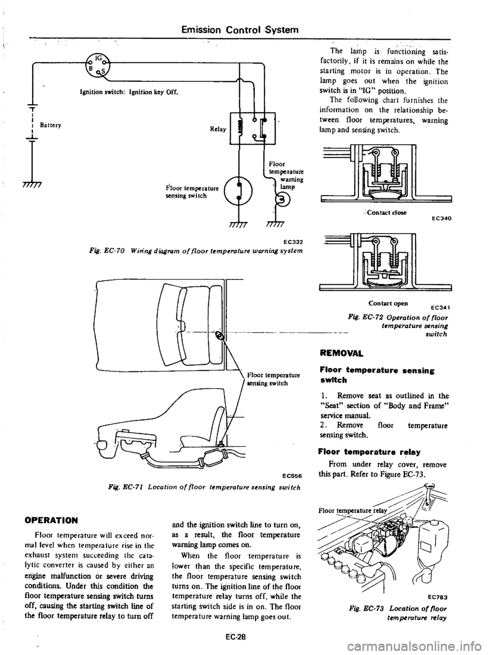
OPERATION
Floor
temperature
will
exceed
nor
mal
level
when
temperature
rise
in
the
exhaust
system
succeeding
the
cata
lytic
converter
is
caused
byeilher
an
engine
malfunction
or
severe
driving
conditions
Under
this
condition
the
floor
temperature
sensing
switch
turns
off
causing
the
starting
switch
line
of
the
floor
temperature
relay
to
turn
off
and
the
ignition
switch
line
to
turn
on
as
a
result
the
floor
temperature
warning
lamp
comes
on
When
the
floor
temperature
is
lower
t
an
the
specific
temperature
the
floor
temperature
sensing
switch
turns
on
The
ignition
line
of
the
floor
temperature
relay
turns
off
while
the
starting
switch
side
is
in
on
The
floor
temperature
warning
lamp
goes
out
EC
2B
The
lamp
is
functioning
sa
tis
factorily
if
it
is
remains
on
while
the
starting
motor
is
in
operation
The
lamp
goes
out
when
the
ignition
switch
is
in
IG
position
The
foUowing
chart
furnishes
the
information
on
the
relationship
be
tween
floor
temperatures
warning
lamp
and
sensing
switch
L
Contact
close
ECJ40
I
Contaclopen
ECJ41
Fig
EC
72
Operation
of
floor
t
mperature
sen6ing
6witch
REMOVAL
Floor
temperature
sensing
switch
1
Remove
seat
Seat
section
of
service
manual
2
Remove
sensing
sWitch
as
outlined
in
the
Body
and
Frame
floor
temperature
Floor
temperature
relay
From
under
relay
cover
remove
this
part
Refer
to
Figure
EC
73
Floortemperature
EC783
Fig
EC
73
Location
of
floor
ttmperature
relay
Page 219 of 537
Engine
Removal
Installation
ENGINE
REMOVAL
AND
INSTAllATION
REMOVAL
INSTALLATION
ENGINE
MOUNTING
INSULATORS
REMOVAL
It
is
much
easier
to
remove
engine
and
transmission
as
a
single
unit
than
to
remove
them
separately
After
re
moval
engine
can
be
separated
from
transntission
assembly
Notes
a
Be
sure
to
hoist
engine
and
jack
up
transmission
in
a
safe
manner
b
Use
fender
cove
to
protect
vehicle
body
1
Remove
battery
2
Scribe
hood
hinge
location
for
proper
reinstallation
and
remove
hood
Note
Have
an
assistant
help
you
so
as
to
prevent
damage
to
body
3
Drain
radiator
coolant
4
Disconnect
upper
and
lower
radiator
hoses
from
engine
5
Remove
two
oil
cooler
hoses
from
lower
end
of
radiator
Auto
ma
tic
transmission
models
only
6
Remove
radiator
shroud
7
Remove
four
bolts
securing
radia
tor
and
detach
radiator
Note
Always
tighten
securing
bolt
at
upper
right
hand
side
together
with
body
harness
terminal
8
Remove
carburetor
air
cleaner
as
follows
Remove
fresh
air
duct
Remove
hot
air
duct
Loosen
air
cleaner
band
bolt
and
air
cleaner
supporting
bolts
Disconnect
air
cleaner
ta
air
pump
hose
Disconnect
air
cleaner
to
rocker
cover
hose
at
rocker
cover
Disconnect
air
cleaner
to
air
control
valve
hose
California
models
only
CONTENTS
ER
2
ER
3
ER
3
FRONT
INSULATOR
REAR
INSULATOR
TIGHTENING
TORQUE
ER
4
ER
4
ER
4
Disconnect
air
deaner
to
A
B
valve
hose
Disconnect
air
cleaner
ta
vacuum
hoses
Note
Protect
carburetor
from
dust
and
foreign
matter
by
placing
cover
over
air
inlet
opening
9
Disconnect
fuel
pump
to
fuel
fdter
hose
and
return
hose
10
Disconnect
carbon
canister
hose
on
engine
side
II
Disconnect
air
pump
air
C1eaner
to
al
p
p
hose
12
Disconnect
following
cables
wires
and
hoses
Engine
ground
cable
Accelerator
wire
at
carburetor
High
tension
cable
between
ignition
coil
and
distributor
Wire
to
distributor
at
body
ter
minal
Wire
to
oil
pressure
switch
Wires
to
thermal
transmitter
Wires
to
B
C
p
D
cut
solenoid
Non
California
models
only
auto
choke
heater
and
anti
dieseling
solenoid
Wires
to
alternator
Wires
to
starter
motor
Heater
inlet
and
outlet
hoses
if
so
equipped
Vacuum
hose
of
Master
Vac
at
in
taJce
manifold
Wires
for
back
up
lamp
switch
Cable
to
speedometer
13
Remove
transmission
control
linkage
from
transmission
Manual
transmission
models
I
Detach
rubber
boot
2
Remove
E
ring
and
control
lever
pin
from
transmission
striking
rod
guide
and
remove
control
lever
ER
2
Fig
ER
l
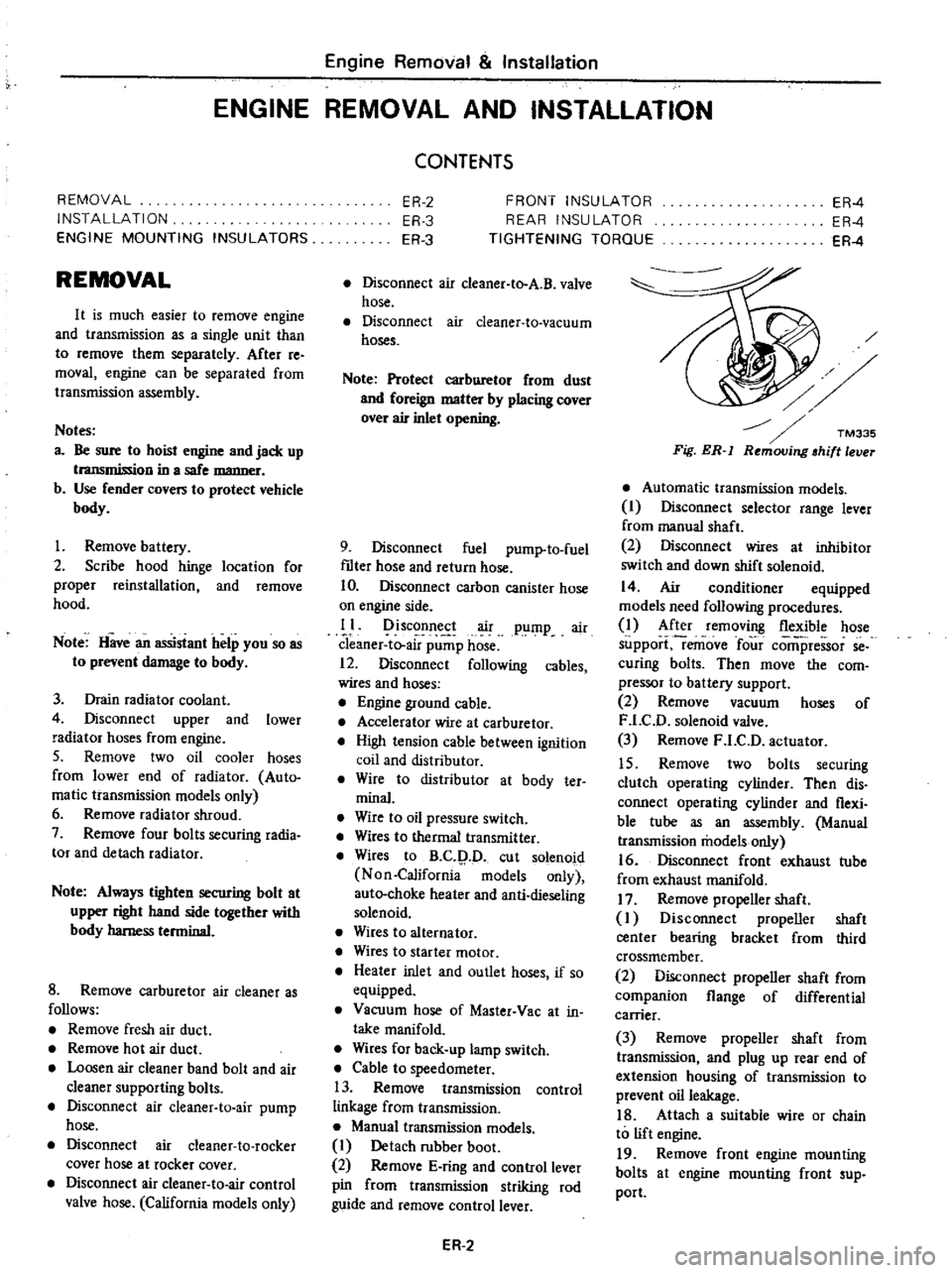
Automatic
transmission
models
I
Disconnect
selector
range
lever
from
manual
shaft
2
Disconnect
wires
at
inhibitor
switch
and
down
shift
solenoid
14
Air
conditioner
equipped
models
need
following
procedures
1
After
removing
flexible
hose
support
remove
four
comi
ressor
se
curing
bolts
Then
move
the
com
pressor
to
battery
support
2
Remove
vacuum
hoses
of
F
LC
D
solenoid
valve
3
Remove
F
LC
D
actuator
15
Remove
two
bolts
securing
clutch
operating
cylinder
Then
dis
connect
operating
cylinder
and
flexi
ble
tube
as
an
assembly
Manual
transmission
models
only
16
Disconnect
front
exhaust
tube
from
exhaust
manifold
17
Remove
propeller
shaft
I
Disconnect
propeller
shaft
center
bearing
bracket
from
third
crossmember
2
Disconnect
propeller
shaft
from
companion
flange
of
differential
carrier
3
Remove
propeller
shaft
from
transmission
and
plug
up
rear
end
of
extension
housing
of
transmission
to
prevent
oil
leakage
18
Attach
a
suitable
wire
or
chain
to
lift
engine
19
Remove
front
engine
mounting
bolts
at
engine
mounting
front
sup
port
Page 429 of 537
Body
Frame
30
For
installation
reverse
above
steps
However
observe
the
following
instructions
i
If
the
cab
body
is
to
be
replaced
note
position
and
location
of
insula
tors
and
washers
used
See
Figure
BF
4
2
Adjust
hand
brake
stroke
pro
perly
3
Air
bleed
brake
and
clutch
system
thorougWy
Cab
body
to
frame
mounting
bolt
torque
1
6
to
2
2
kg
m
12
to
16
ft
Ib
o
i
k
q
1Q
j
b
crru
V
J
8F630
rr
1
4
n
Fig
BF
5
Lifting
up
cab
body
REAR
BODY
1
Bolster
2
Shim
B
3
Bolster
4
Shim
A
5
Frame
6
Rubber
washer
7
Plain
washer
BF664
Fig
BF
6
Rear
body
mountings
REAR
BODY
REMOVAL
AND
INSTALLATION
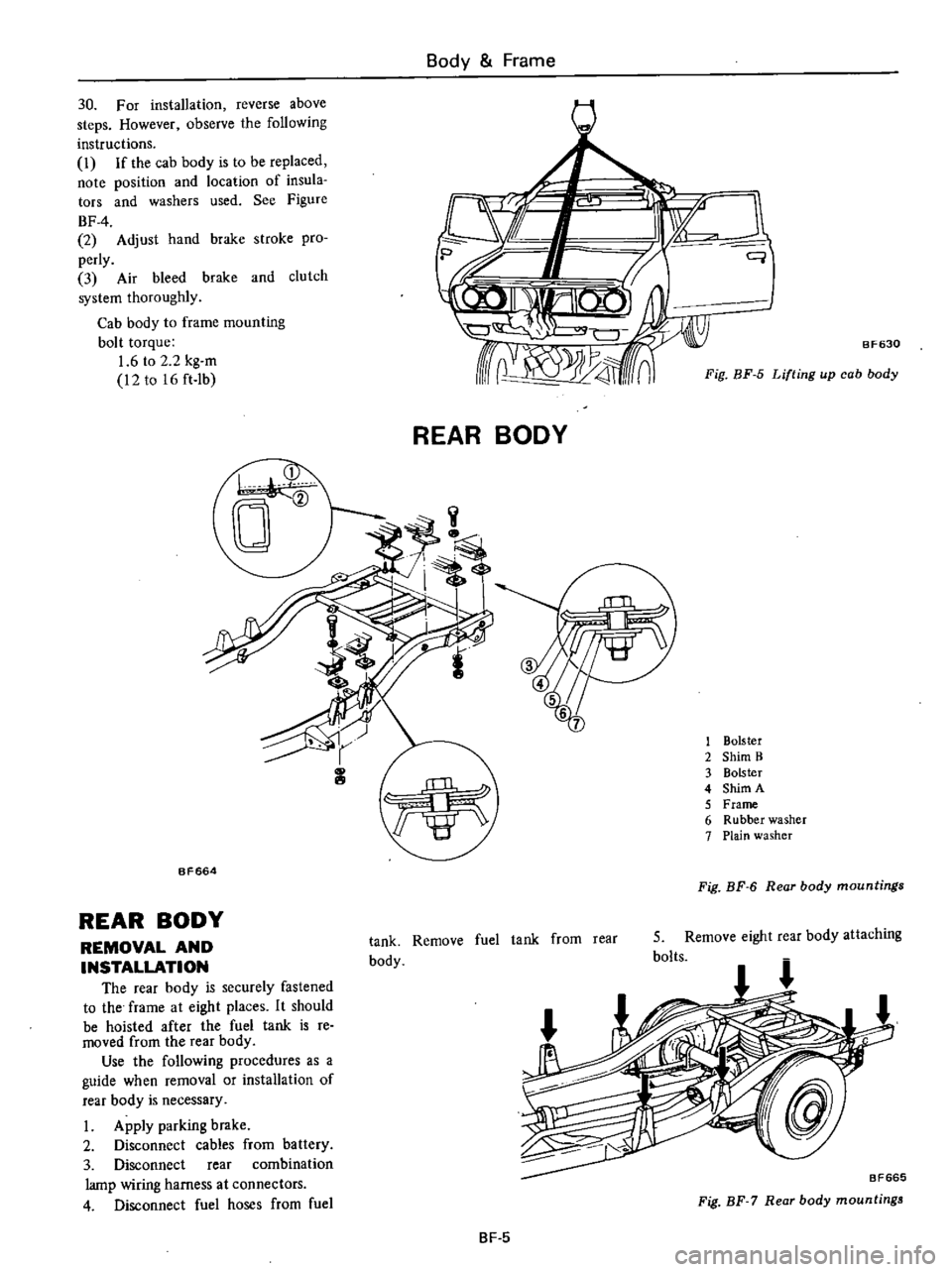
The
rear
body
is
securely
fastened
to
the
frame
at
eight
places
It
should
be
hoisted
after
the
fuel
tank
is
re
moved
from
the
rear
body
Use
the
following
procedures
as
a
guide
when
removal
or
installation
of
rear
body
is
necessary
I
Apply
parking
brake
2
Disconnect
cables
from
battery
3
Disconnect
rear
combination
lamp
wiring
harness
at
connectors
4
Disconnect
fuel
hoses
from
fuel
tank
Remove
fuel
tank
from
rear
body
5
Remove
eight
rear
body
attaching
bolts
BF665
Fig
BF
7
Rear
body
mountings
BF
5
Page 450 of 537
Body
Electrical
System
Room
lamp
and
engine
compartment
lamp
system
FUSE
BLOC
K
C
J
QA
C
J
CJ
CJ
CJ
1
100
I
2
I
I
t1
Wf
t
fi
FUSIBLE
LINK
ROOM
LAMP
t
I
6
I
II
lA
FUSE
o
C
1
BATTERY
I
I
DOOR
SWITCH
L
H
l
ENGINE
ROOM
LAMP
I
0
I
1
HOOD
SWITCt
f
I
c
I
DOOR
SWITCHIR
H
l
Fig
BE
5
Room
lamp
and
engine
compartment
lamp
system
BE852A
HEADLAMP
if
BE300
Fig
BE
6
Head
amp
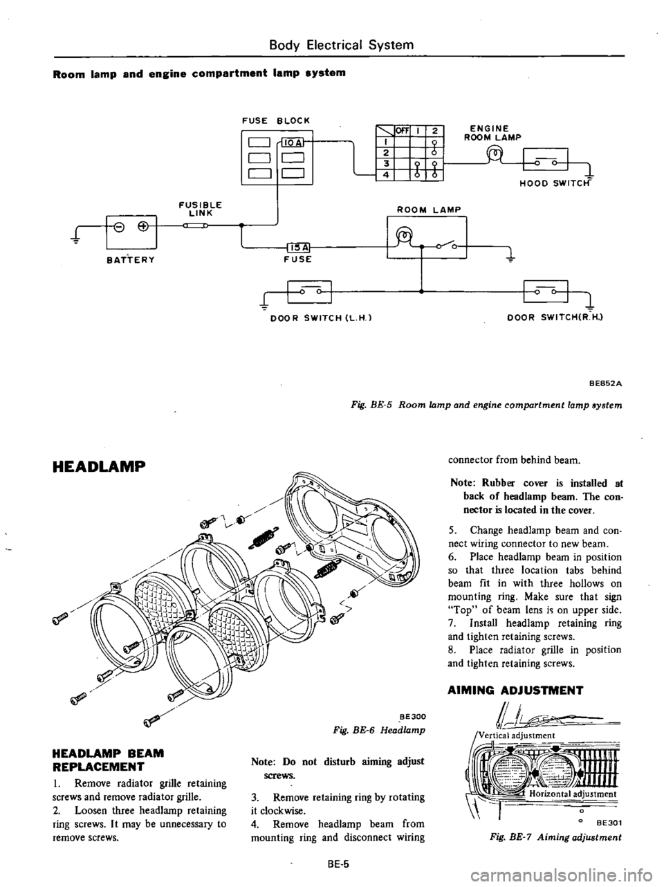
HEADLAMP
BEAM
REPLACEMENT
I
Remove
radiator
grille
retaining
screws
and
remove
radiator
grille
2
Loosen
three
headlamp
retaining
ring
screws
I
t
may
be
unnecessary
to
remove
screws
Note
Do
not
disturb
aiming
adjust
screws
3
Remove
retaining
ring
by
rotating
it
clockwise
4
Remove
headlamp
beam
from
mounting
ring
and
disconnect
wiring
8E
5
connector
from
behind
beam
Note
Rubber
cover
is
installed
at
back
of
headlamp
beam
The
con
nector
is
located
in
the
cover
5
Change
headlamp
beam
and
con
nect
wiring
connector
to
new
beam
6
Place
headlamp
beam
in
position
so
that
three
location
tabs
behind
beam
fit
in
with
three
hollows
on
mounting
ring
Make
sure
that
sign
Top
of
beam
lens
i
i
on
upper
side
7
Install
headlamp
retaining
ring
and
tighten
retaining
screws
8
Place
radIator
grille
in
position
and
tighten
retaining
screws
AIMING
ADJUSTMENT
lJ
ii
i
tooi
1
Ji
Y
4
nnn
4
I
Horiz
tal
ad
justment
l
BE30l
Fig
BE
7
Aiming
adjustment
Page 455 of 537
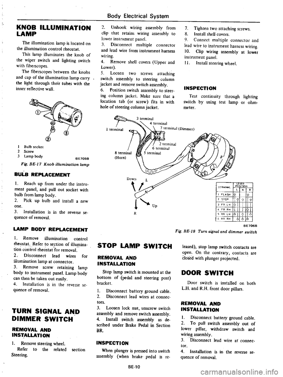
KNOB
ILLUMINATION
LAMP
The
illumination
lamp
is
located
on
the
illumination
control
rheostat
This
lamp
illuminates
the
knob
of
the
wiper
switch
and
lighting
switch
with
fiberscopes
The
fiberscopes
between
the
knobs
and
cap
of
the
illumination
lamp
carry
the
light
through
their
tubes
with
the
inner
reflective
walJ
CID
1
Bulb
socket
2
Screw
3
Lamp
body
8E705B
Fig
BE
17
Knob
illumination
lamp
BULB
REPLACEMENT
I
Reach
up
from
under
the
instru
ment
panel
and
pull
out
socket
with
bulb
from
lamp
body
2
Pick
up
bulb
and
install
a
new
one
3
Installation
is
in
the
reverse
se
quence
of
removal
LAMP
BODY
REPLACEMENT
1
Remove
illumination
control
rheostat
Refer
to
section
of
illumina
ti
on
control
rheostat
for
removal
2
Disconnect
lead
wires
for
illumination
lamp
at
connector
3
Remove
screw
retaining
lamp
body
to
instrument
panel
Lamp
body
can
then
be
taken
out
easily
4
Installation
is
in
the
reverse
se
quence
of
removal
TURN
SIGNAL
AND
DIMMER
SWITCH
REMOVAL
AND
INSTALLATION
I
Remove
steering
wheel
Refer
to
the
related
section
Steering
Body
Electrical
System
2
Unhook
wiring
assembly
from
clip
that
retains
wiring
assembly
to
lower
instrument
panel
3
Disconnect
multiple
connector
and
lead
wire
from
instrument
harness
wiring
4
Remove
shell
covers
Upper
and
Lower
5
Loosen
two
screws
attaching
switch
assembly
to
steering
column
jacket
and
remove
switch
assembly
6
Position
switch
assembly
to
steer
ing
column
jacket
Make
sure
that
a
location
tab
or
screw
fits
in
with
hole
of
steering
column
jacket
7
Tighten
two
attaching
screws
8
Install
shell
covers
9
Connect
multiple
connector
and
lead
wire
to
instrument
harness
wiring
10
Clip
wiring
assembly
at
lower
instrument
panel
II
Install
steering
wheel
INSPECTION
Test
continuity
through
lighting
switch
by
using
test
lamp
or
ohm
meter
3
terminal
4
terminal
7
terminal
Dimmer
R
STOP
LAMP
SWITCH
REMOVAL
AND
INSTALLATION
Stop
lamp
switch
is
mounted
at
the
bottom
of
pedal
and
steering
post
bracket
I
Disconnect
battery
ground
cable
2
Disconnect
lead
wires
at
coonee
tors
3
Loosen
lock
nut
unscrew
switch
assembly
and
remove
switch
assembly
4
Install
switch
assembly
as
de
scribed
under
Brake
Pedal
in
Section
BR
INSPECTION
When
plunger
is
pressed
into
switch
assembly
when
brake
pedal
is
reo
8El0
I
Ll
vt
r
I
ER
4JN
l
L
PlOSITlON
RI
j
LASH
n
I
I
12
STOP
9
91
I
JFRe
I
I
II
L
I
III
11
I
I
II
161
I
61616
BE706B
Fig
BE
IS
Turn
signal
and
dimmer
switch
leased
stop
lamp
switch
contacts
are
open
On
the
contrary
contacts
are
closed
with
plunger
projected
DOOR
SWITCH
Door
switch
is
installed
on
both
L
H
and
R
H
front
door
pillars
REMOVAL
AND
INSTALLATION
I
Disconnect
battery
ground
cable
2
To
pull
switch
assembly
out
of
lower
pillar
withdraw
switch
and
wiring
assembly
3
Disconnect
lead
wire
at
cannee
tor
4
Installation
is
in
the
reverse
se
quence
of
removal