air bleeding DATSUN PICK-UP 1977 Service Manual
[x] Cancel search | Manufacturer: DATSUN, Model Year: 1977, Model line: PICK-UP, Model: DATSUN PICK-UP 1977Pages: 537, PDF Size: 35.48 MB
Page 229 of 537

Inspection
Note
To
clean
or
wash
all
parts
of
master
cylinder
operating
cylinder
and
piping
clean
brake
fluid
must
be
used
Never
use
minera10ils
llUch
as
gasoline
and
kerosene
It
will
ruin
the
rubber
parts
of
the
hydrau
lic
system
I
Check
cylinder
and
piston
for
uneven
wear
or
damage
and
if
neces
sary
replace
2
If
the
clearance
between
cylinder
and
piston
is
more
than
0
15
mm
0
0059
in
replace
cylinder
3
Renew
piston
cup
when
dis
assembled
It
must
also
be
replaced
when
wear
or
deformation
due
to
fatigue
or
damage
is
found
4
Damaged
dust
cover
oil
reservoir
or
cap
should
be
replaced
Return
spring
and
valve
spring
must
also
be
replaced
when
they
are
broken
or
weak
5
Replace
clutch
hose
and
tube
if
any
abnormal
sign
of
damage
or
de
fro
ti
n
is
found
OPERATING
CYLINDER
Removal
and
installation
Removal
1
Detach
clutch
hose
from
operat
ing
cylinder
2
Remove
two
bolts
securing
op
erating
cylinder
to
clutch
housing
Installation
Install
in
the
reverse
order
of
re
moval
Observe
the
following
instructions
Bleed
air
thoroughly
from
clutch
hydraulic
system
2
Do
not
install
return
spring
or
clutch
will
not
be
disengaged
properly
Tightening
torque
Operating
cylinder
securing
bolt
2
5
to
3
5
kg
m
18
to
25
ft
lb
Bleeder
screw
0
7
to
0
9
kg
m
5
1
to
6
5
ft
Ib
Clutch
hose
connector
1
7
to
2
0
kg
m
12
to
14
ft
b
CLUTCH
Disassembly
and
assembly
Disassembly
1
Remove
push
rod
with
dust
cover
2
Remove
piston
assembly
and
pis
ton
spring
3
Remove
bleeder
screw
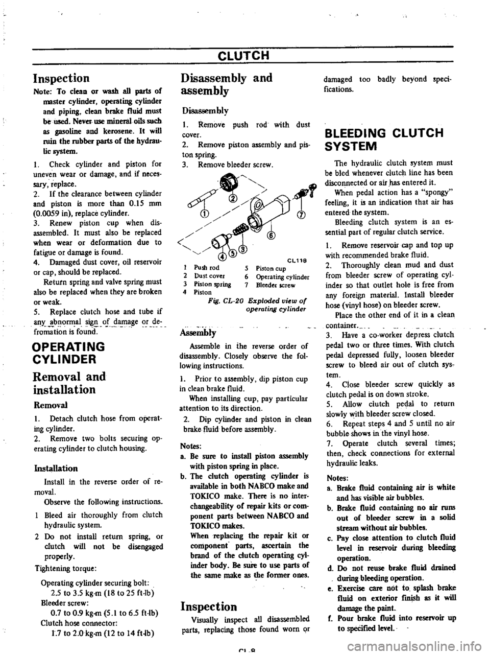
1
6
Cl11B
5
Piston
cup
6
Operating
cylinder
7
Bleeder
screw
1
Push
rod
2
Dust
cover
3
Piston
spring
4
Piston
Fig
CL
20
Exploded
view
of
operating
cyUnder
Assembly
Assemble
in
the
reverse
order
of
disassembly
Closely
observe
the
fol
lowing
instructions
1
Prior
to
assembly
dip
piston
cup
in
clean
brake
fluid
When
installing
cup
pay
particular
attention
to
its
direction
2
Dip
cylinder
and
piston
in
clean
brake
fluid
before
assembly
Notes
a
Be
sure
to
install
piston
assembly
with
piston
spring
in
place
b
The
clutch
operating
cylinder
is
available
in
both
NABCO
make
and
TOKICO
make
There
is
no
inter
changeability
of
repair
kits
or
com
ponent
parts
between
NABCO
and
TOKICO
makes
When
replacing
the
repair
kit
or
component
parts
ascertain
the
brand
of
the
clutch
operating
cyl
inder
bndy
Be
sure
to
use
parts
of
the
same
make
as
the
former
ones
Inspection
Visually
inspect
all
disassembled
parts
replacing
those
found
worn
or
rl
Q
damaged
too
badly
beyond
speci
fications
BLEEDING
CLUTCH
SYSTEM
The
hydraulic
clutch
system
must
be
bled
whenever
clutch
line
has
been
disconnected
or
air
has
entered
it
When
pedal
action
has
a
spongy
feeling
it
is
an
indication
that
air
has
entered
the
system
Bleeding
clutch
system
is
an
es
sential
part
of
regular
clutch
service
I
Remove
reservoir
cap
and
top
up
with
recommended
brake
fluid
2
Thoroughly
clean
mud
and
dust
from
bleeder
screw
of
operating
cyl
inder
so
that
outlet
hole
is
free
from
any
foreign
rnaterial
Install
bleeder
hose
vinyl
hose
on
bleeder
screw
Place
the
other
end
of
it
in
a
clean
container
3
Have
a
co
worker
depress
clutch
pedal
two
or
three
times
With
clu
tch
pedal
depressed
fully
loosen
bleeder
screw
to
bleed
air
out
of
clutch
sys
tern
4
Close
bleeder
screw
quickly
as
clutch
pedal
is
on
down
stroke
5
Allow
clutch
pedal
to
return
slowly
with
bleeder
screw
closed
6
Repeat
steps
4
and
5
until
no
air
bubble
shows
in
the
vinyl
hose
7
Operate
clutch
several
times
then
check
connections
for
external
hydraulic
leaks
Notes
a
Brake
fluid
containing
air
is
white
and
has
visible
air
bubbles
b
Brake
fluid
containing
no
air
runs
out
of
bleeder
screw
in
a
solid
stream
without
air
bubble
c
Pay
close
attention
to
clutch
fluid
level
in
reservoir
during
bleeding
operation
d
Do
not
reuse
brake
fluid
drained
during
bleeding
operation
e
Exercise
care
not
to
splash
brake
fluid
on
exterior
fInish
as
it
will
damage
the
paint
f
Pour
brake
fluid
into
reservoir
up
to
specifIed
level
Page 378 of 537

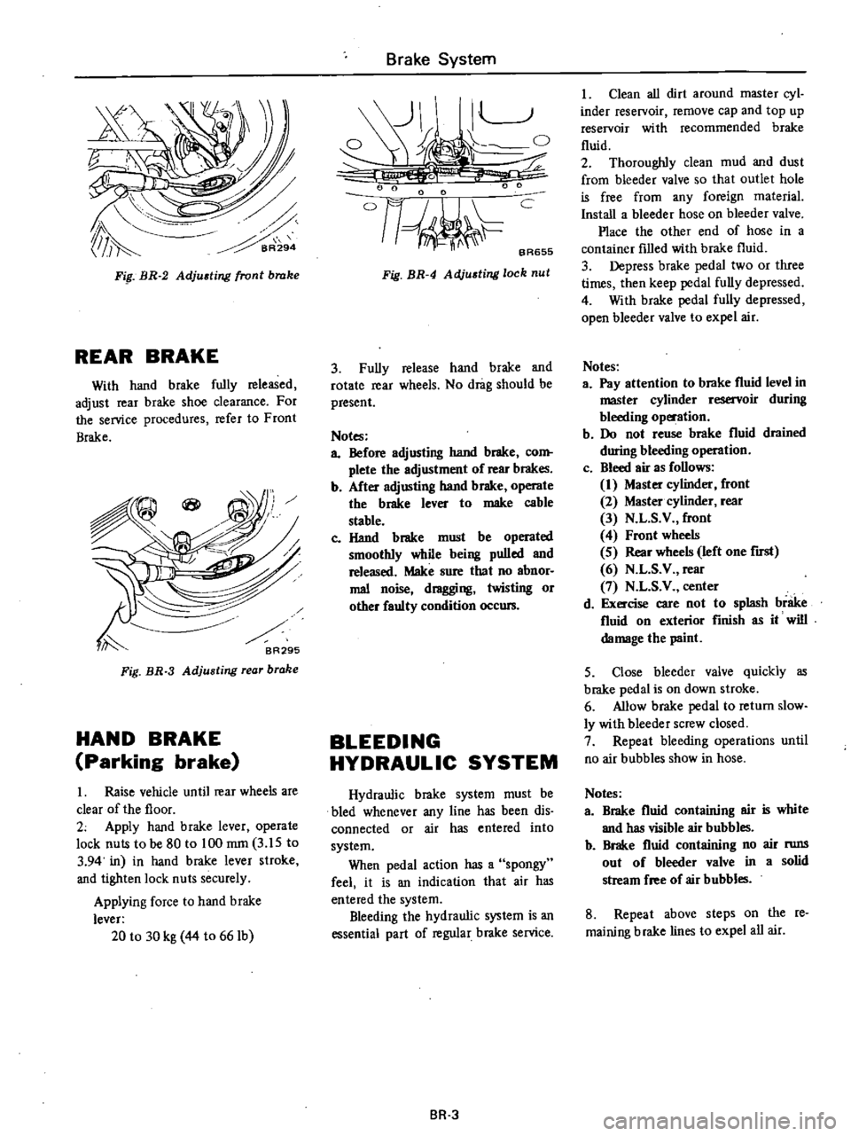
Fip
BR
2
Adjusting
front
brake
REAR
BRAKE
With
hand
brake
fully
released
adjust
rear
brake
shoe
clearance
For
the
service
procedures
refer
to
Front
Brake
Fig
BR
3
Adjusting
rear
brake
HAND
BRAKE
Parking
brake
I
Raise
vehicle
until
rear
wheels
are
clear
of
the
floor
2
Apply
hand
brake
lever
operate
lock
nuts
to
be
80
to
100
mrn
3
lS
to
3
94
in
in
hand
brake
lever
stroke
and
tighten
lock
nuts
securely
Applying
force
to
hand
brake
lever
20
to
30
kg
44
to
661b
Brake
System
1
t
0
t
6
0
I
o
nJ
c
BA655
Fig
BR
4
Adjusting
lock
nut
3
Fully
release
hand
brake
and
rotate
rear
wheels
No
drag
should
be
present
Notes
a
Before
adjusting
hand
brake
com
plete
the
adjustment
of
rear
brakes
b
After
adjusting
hand
brake
operate
the
brake
lever
to
make
cable
stable
c
Hand
brake
must
be
operated
smoothly
while
being
pulled
and
released
Make
sure
that
no
abnor
mal
noise
dragging
twisting
or
other
faulty
condition
occurs
BLEEDING
HYDRAUL
Ie
SYSTEM
Hydraulic
brake
system
must
be
bled
whenever
any
line
has
been
dis
connected
or
air
has
entered
into
system
When
pedal
action
has
a
spongy
feel
it
is
an
indication
that
air
has
entered
the
system
Bleeding
the
hydraulic
system
is
an
essential
part
of
regular
brake
service
BR
3
I
Clean
all
dirt
around
master
cyl
inder
reservoir
I
remove
cap
and
top
up
reservoir
with
recommended
brake
fluid
2
Thoroughly
clean
mud
and
dust
from
bleeder
valve
so
that
outlet
hole
is
free
from
any
foreign
material
Install
a
bleeder
hose
on
bleeder
valve
Place
the
other
end
of
hose
in
a
container
filled
with
brake
fluid
3
Depress
brake
pedal
two
or
three
times
then
keep
pedal
fully
depressed
4
With
brake
pedal
fully
depressed
open
bleeder
valve
to
expel
air
Notes
a
Pay
attention
to
brake
fluid
level
in
master
cylinder
reservoir
during
bleeding
operation
b
Do
not
reuse
brake
fluid
drained
during
bleeding
operation
c
Bleed
air
as
follows
1
Master
cylinder
front
2
Master
cylinder
rear
3
N
L
S
V
front
4
Front
wheels
S
Rear
wheels
left
one
first
6
N
L
S
V
rear
7
N
L
S
V
center
d
Exercise
care
not
to
splash
brake
fluid
on
exterior
finish
as
it
will
damage
the
paint
5
Close
bleeder
valve
quickly
as
brake
pedal
is
on
down
stroke
6
Allow
brake
pedal
to
return
slow
ly
with
bleeder
screw
closed
7
Repeat
bleeding
operations
until
no
air
bubbles
show
in
hose
Notes
a
Brake
fluid
containing
air
is
white
and
has
visible
air
bubbles
b
Brake
fluid
containing
no
air
nms
out
of
bleeder
valve
in
a
solid
stream
free
of
air
bubbles
8
Repeat
above
steps
on
the
re
maining
brake
lines
to
expel
all
air