engine overheat DATSUN PICK-UP 1977 Service Manual
[x] Cancel search | Manufacturer: DATSUN, Model Year: 1977, Model line: PICK-UP, Model: DATSUN PICK-UP 1977Pages: 537, PDF Size: 35.48 MB
Page 42 of 537
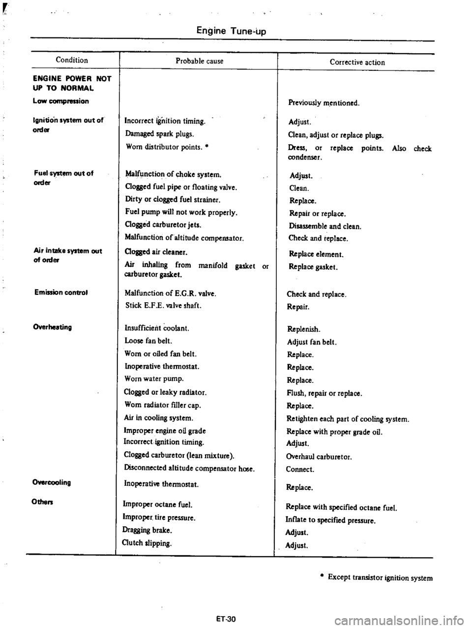
Condition
ENGINE
POWER
NOT
UP
TO
NORMAL
Low
compression
Ignition
system
out
of
order
Fuel
system
out
of
order
Air
intake
system
out
of
order
Emission
control
Overheating
O
cooIing
Others
Engine
Tune
up
Probable
cause
Incorrect
iSnition
timing
Damaged
spark
plugs
Worn
distributor
points
Malfunction
of
choke
system
Clogged
fuel
pipe
or
floating
valve
Dirty
or
clogged
fuel
strainer
Fuel
pump
will
not
work
properly
C10ssed
carburetor
jets
Malfunction
of
altitude
compensator
CIOJBed
air
cleaner
Ail
inhaling
from
manifold
gasket
or
carburetor
gasket
Malfunction
of
E
G
R
valve
Stick
E
F
E
valve
shaft
Insufficient
coolant
Loose
fan
belt
Worn
or
oiled
fan
belt
Inoperative
thermostat
Worn
water
pump
Clogged
or
leaky
radiator
Worn
radiator
filler
cap
Ail
in
cooling
system
Improper
engine
oil
grade
Incorrect
ignition
timing
Clossed
carburetor
lean
mixture
Disconnected
altitude
compensator
hOlle
Inoperative
thermostat
Improper
octane
fuel
L
j
tire
pressure
Dragging
brake
Clutch
slipping
ET
30
Corrective
action
Previously
mentioned
Adjust
Clean
adjust
or
replace
plull
Dress
or
replace
points
Also
check
condenser
Adj
lst
Clean
Replace
Repair
or
replace
Disassemble
and
clean
Check
and
replace
Replace
element
Replace
gasket
Check
and
replace
Repair
Replenish
Adjust
fan
belt
Replace
Replace
Replace
Flush
repair
or
replace
Replace
Retighten
each
part
of
cooling
system
Replace
with
proper
grade
oil
Adjust
Overhaul
carburetor
Connect
Replace
Replace
with
specified
octane
fuel
Inflate
to
specified
pressure
Adjust
Adjust
Except
transistor
ignition
system
Page 44 of 537
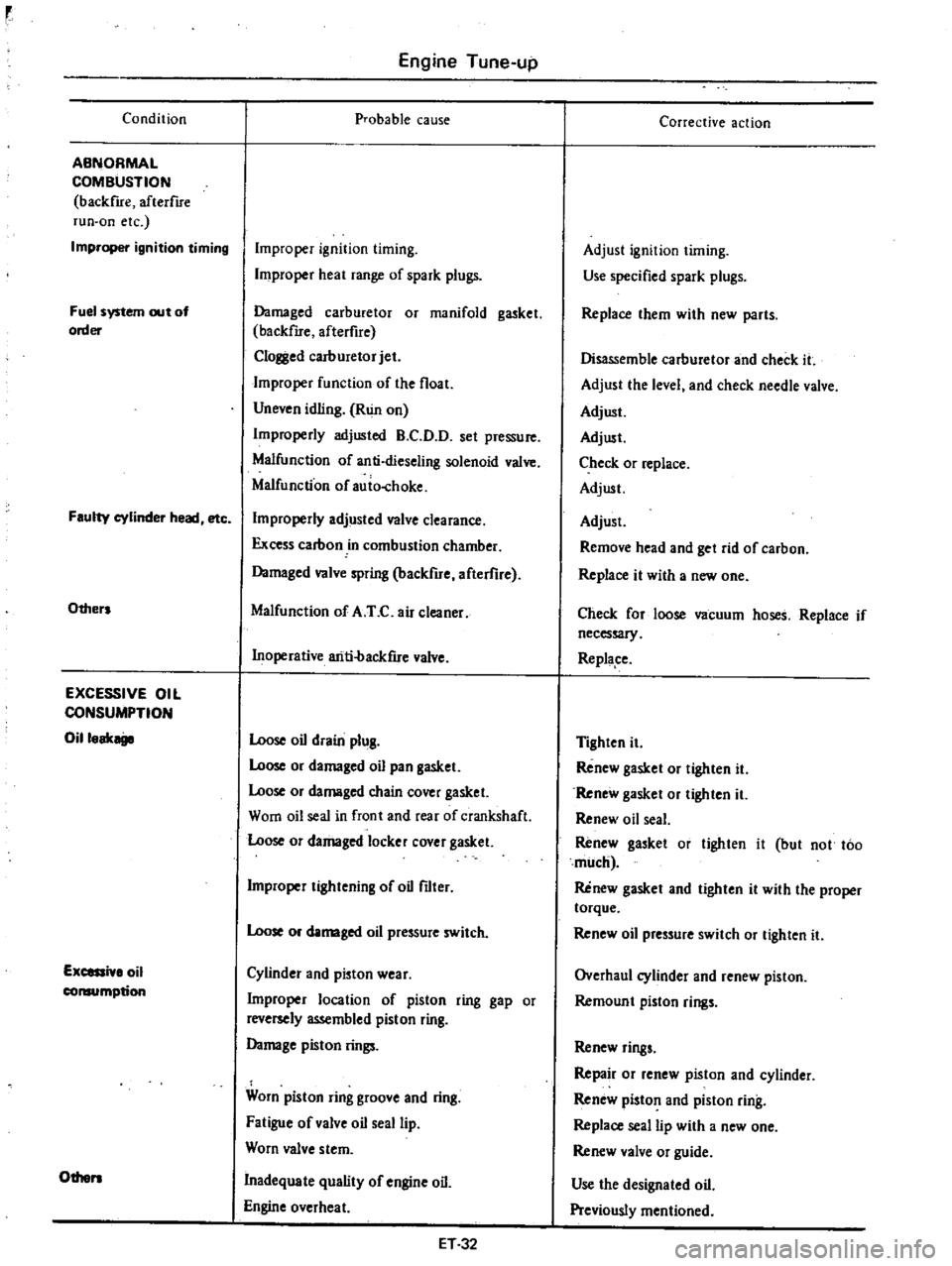
Condition
ABNORMAL
COMBUSTION
backfue
afterflre
run
on
etc
Improper
ignition
timing
Fuel
system
out
of
order
Faulty
cylinder
head
etc
Others
EXCESSIVE
OIL
CONSUMPTION
Oilloak
Excessi
lo
oil
consumption
Others
Engine
Tune
up
probable
cause
Improper
ignition
timing
Improper
heat
range
of
spark
plugs
Damaged
carburetor
or
manifold
gasket
backfue
afterfire
Clol
l
ed
carburetor
jet
Improper
function
of
the
float
Uneven
idling
Run
on
Improperly
adjusted
B
C
D
D
set
pressure
Malfunction
of
anti
dieseling
solenoid
valve
Malfunction
of
auio
choke
Improperly
adjusted
valve
clearance
Excess
carbon
in
combustion
chamber
Damaged
valve
spring
backfire
afterflre
Malfunction
of
A
T
C
air
cleaner
Inoperative
ariti
backfue
valve
Loose
oil
drain
plug
Loose
or
damaged
oil
pan
gasket
Loose
or
damaged
chain
cover
gasket
Worn
oil
seal
in
front
and
rear
of
crankshaft
Loose
or
damaged
locker
cover
gasket
Improper
tightening
of
oil
filter
Loose
or
damaged
oil
pressure
switch
Cylinder
and
pioton
wear
Improper
location
of
piston
ring
gap
or
reversely
assembled
piston
ring
Damage
piston
rings
Worn
piston
ring
groove
and
ring
Fatigue
of
valve
oil
seal
lip
Worn
valve
stem
Inadequate
quality
of
engine
oil
Engine
overheat
ET32
Corrective
action
Adjust
ignition
timing
Use
specified
spark
plugs
Replace
them
with
new
parts
Disassemble
carburetor
and
check
it
Adjust
the
level
and
check
needle
valve
Adjust
Adjust
Check
or
replace
Adjust
Adjust
Remove
head
and
get
rid
of
carbon
Replace
it
with
a
new
one
Check
for
loose
vacuum
hoses
Replace
if
necessary
Replape
Tighten
it
Renew
gasket
or
tighten
it
Renew
gasket
or
tighten
it
Renew
oil
seal
Renew
gasket
or
tighten
it
but
not
too
much
Renew
gasket
and
tighten
it
with
the
proper
torque
Renew
oil
pressure
switch
or
tighten
it
Overhaul
cylinder
and
renew
piston
Remoun
t
piston
rings
Renew
rings
Repair
or
renew
piston
and
cylinder
Renew
piston
and
piston
ring
Replace
seal
lip
with
a
new
one
Renew
valve
or
guide
Use
the
designated
oil
Previously
mentioned
Page 45 of 537

Condition
POOR
FUEL
ECONOMY
Se
the
xplanation
of
the
pow
r
dec
Oth
n
PROBLEM
IN
OTHER
FUNCTIONS
D
cr
d
oil
p
ssure
Excessive
wear
on
the
sliding
parts
Scuffing
of
sliding
parts
Floor
temperature
too
high
California
only
Engine
Tune
up
Probable
cause
Exceeding
idling
revolution
Inoperative
acceleration
recovery
Fuel
leakage
Malfunction
of
B
C
D
D
Malfunction
of
A
r
C
air
cleaner
Inadequate
oil
quality
Overheat
Worn
oil
pump
regulator
valve
Functional
deterioration
of
oil
pump
Blocked
oil
f1lter
Increased
clearance
in
various
sliding
parts
Blocked
oil
strainer
Inoperative
oil
gauge
pressure
switch
Oil
pressure
decreases
Improper
quality
or
contamination
of
oil
Damaged
air
cleaner
Overheat
or
overcoal
Improper
fuel
mixture
Decrease
of
oil
pressure
Insufficient
clearances
Overhea
t
Improper
fuel
mixture
Problem
in
fuel
system
Refer
to
Inspec
tion
of
Fuel
System
Problem
in
ignition
system
Refer
to
In
spection
of
Ignition
System
ET33
Corrective
action
Adjust
it
to
the
designated
rpm
Adjust
it
Repair
or
tighten
the
connection
of
fuel
pipes
Adjust
Check
and
replace
Use
the
designated
oil
Previously
mentioned
Disassemble
oil
pump
and
repair
or
renew
it
Repair
or
replace
it
with
a
new
one
Renew
it
Disassemble
and
replace
the
worn
parts
with
new
ones
Oeanit
Replace
it
with
a
new
one
Previousiy
mentioned
Exchange
the
oil
with
proper
one
and
change
element
Change
elemen
t
Previously
mentioned
Check
the
fuel
system
Previously
mentioned
Readjust
to
the
designated
clearances
Previously
mentioned
Check
the
fuel
system
Check
and
repair
Check
and
repair
Page 77 of 537

Condition
Seized
valve
seat
Excessively
worn
cylinder
and
piston
Faulty
connecting
rod
Faulty
crankshaft
bearing
Engine
Mechanical
Probable
cause
Improper
valve
clearance
Weakened
valve
spring
Thin
valve
head
edge
Narrow
valve
seat
Overheating
Over
speeding
Stuck
valve
guide
Shortage
of
engine
oil
Dirty
engine
oil
Poor
quality
of
oiL
Overheating
Wrong
assembly
of
piston
with
connecting
rod
Improper
piston
ring
clearance
Broken
piston
ring
Dirty
aii
cleaner
Mixture
too
rich
Engine
over
run
Stuck
choke
valve
Overchoking
Shortage
of
engine
oil
Low
oil
pressure
Poor
quality
of
engine
oil
Rough
surface
of
craokshaft
Clogged
oil
passage
Bearing
worn
or
eccentric
Bearingimproperly
assembled
Loose
bearing
Connecting
rod
alignment
incorrect
Shortage
of
engine
oil
Low
oil
pressure
Poor
quality
of
engine
oil
Craokshaft
journal
worn
or
out
of
round
Clogged
oil
passage
in
crankshaft
Bearing
worn
or
eccentric
Bearing
improperly
assembled
Eccentric
craokshaft
or
bearing
EM
32
Corrective
action
Adjust
Replace
Replace
valve
Reface
Repair
or
replace
Drive
at
proper
speeds
Repair
Add
or
replace
oil
Clean
crankcase
replace
oil
and
oil
niter
element
Use
right
oil
Repair
or
replace
Repair
or
replace
Adjust
Replace
Clean
Adjust
Drive
at
proper
speeds
Clean
and
adjust
Start
correct
way
Add
oiL
Correct
Use
proper
oil
Grind
and
replace
bearing
Clean
Replace
Correct
Replace
Repair
or
replace
Add
or
replace
Correct
Use
proper
oil
Repair
Clean
Replace
Correct
Replace
Page 96 of 537
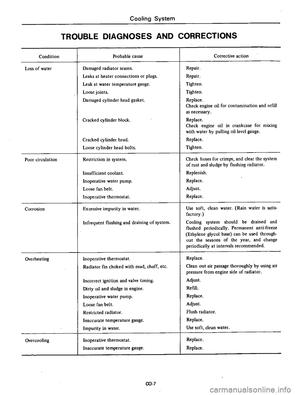
Condition
Loss
of
water
Poor
circulation
Corrosion
Overheating
Overcooling
Cooling
System
TROUBLE
DIAGNOSES
AND
CORRECTIONS
Probable
cause
Damaged
radiator
seams
Leaks
at
heater
connections
or
plugs
Leak
at
water
temperature
gauge
Loose
joints
Damaged
cylinder
head
gasket
Cracked
cylinder
block
Cracked
cylinder
head
Loose
cylinder
head
bolts
Restriction
in
system
Insufficient
coolant
Inoperative
water
pump
Loose
fan
belt
Inoperative
thermostat
Excessive
impurity
in
water
Infrequent
flushing
and
draining
of
system
Inoperative
thermostat
Radiator
fin
choked
with
mud
chaff
etc
Incorrect
ignition
and
valve
timing
Dirty
oil
and
sludge
in
engine
Inoperative
water
pump
Loose
fan
belt
Restricted
radiator
Inaccurate
temperature
gauge
Impurity
in
water
Inoperative
thermostat
Inaccurate
temperature
gauge
CO
7
Corrective
action
Repair
Repair
Tigh
ten
Tighten
Replace
Check
engine
oil
for
contamination
and
refill
as
necessary
Replace
Check
engine
oil
in
crankcase
for
mixing
with
water
by
pulling
oil
level
gauge
Replace
Tighten
Check
hoses
for
crimps
and
clear
the
system
of
rust
and
sludge
by
flushing
radiator
Replenish
Replace
Adjust
Replace
Use
soft
clean
water
Rain
water
is
satis
factory
Cooling
system
should
be
drained
and
flushed
periodically
Permanent
anti
freeze
Ethylene
glycol
base
can
be
used
through
out
the
seasons
of
the
year
and
change
periodically
at
intervals
recommended
Replace
Clean
out
air
passage
thoroughly
by
using
air
pressure
from
engine
side
of
radiator
Adjust
Refill
Replace
Adjust
Flush
radiator
Replace
Use
soft
clean
water
Replace
Replace
Page 145 of 537
Minimizes
exhaust
gas
tempera
lure
rise
2
Minimizes
horsepower
losses
re
suiting
from
air
injection
into
the
exhaust
system
3
Protects
pump
from
excessive
back
pressure
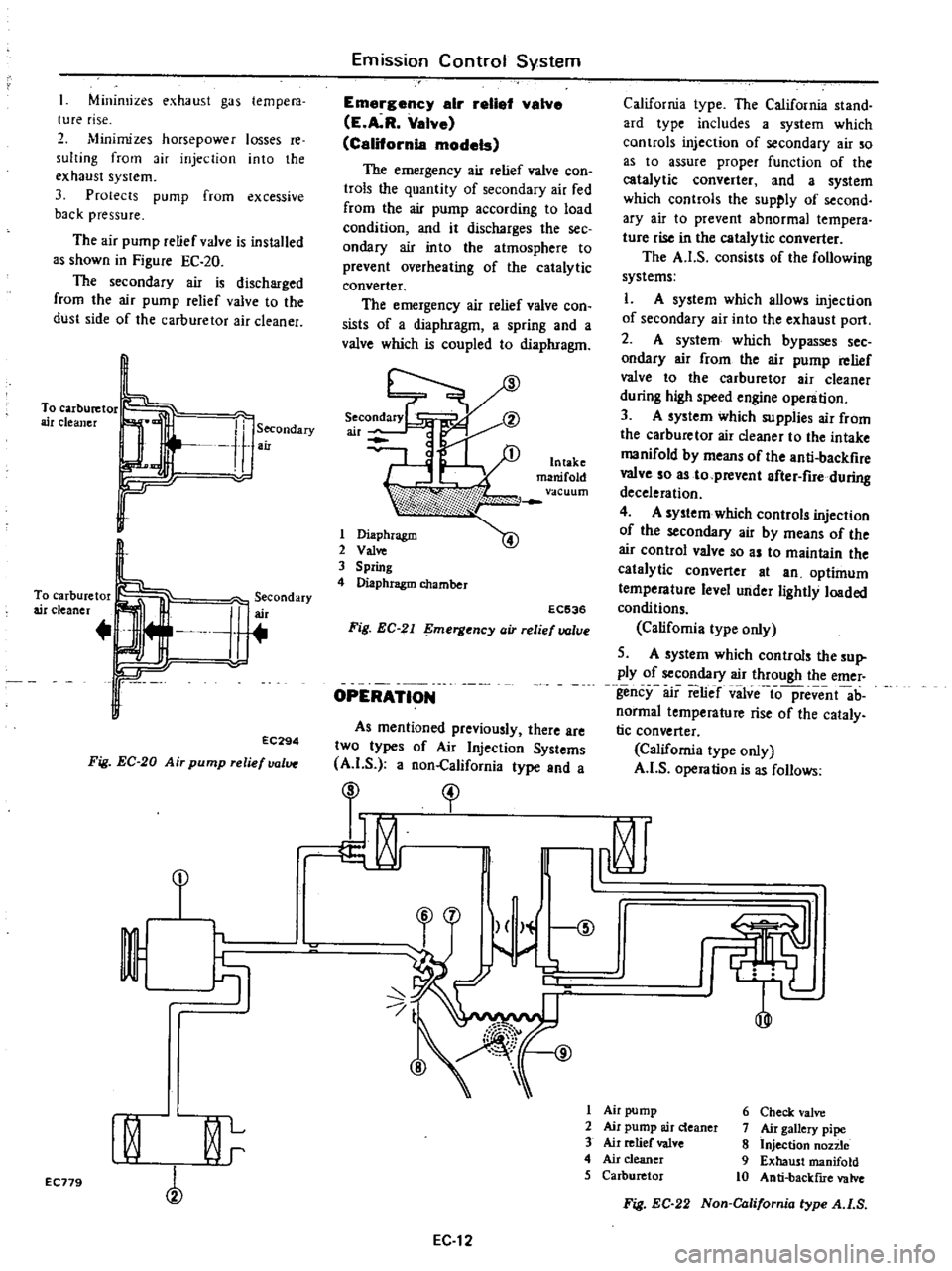
The
air
pump
relief
valve
is
installed
as
shown
in
Figure
EC
20
The
secondary
air
is
discharged
from
the
air
pump
relief
valve
to
the
dust
side
of
the
carburetor
air
cleaner
To
carburetor
air
cleaner
Secondary
air
To
carburetor
air
cleaner
J
erCOndary
r
r
EC294
Fig
EC
20
Air
pump
relief
valve
Emission
Control
System
Emargency
air
retial
valve
E
A
R
Valve
California
models
The
emergency
air
relief
valve
con
trols
the
quantity
of
secondary
air
fed
from
the
air
pump
according
to
load
condition
and
it
discharges
the
see
ondary
air
into
the
atmosphere
to
prevent
overheating
of
the
catalytic
converter
The
emergency
air
relief
valve
con
sists
of
a
diaphragm
a
spring
and
a
valve
which
is
coupled
to
diaphragm
1
Diaphragm
2
Val
3
Spring
4
Diaphragm
chamber
EC536
Fig
EC
21
mergency
air
relief
valve
OPERATION
As
mentioned
previously
there
are
two
types
of
Air
Injection
Systems
A
I
S
a
non
California
type
and
a
California
type
The
California
stand
ard
type
includes
a
system
which
controls
injection
of
secondary
air
so
as
to
assure
proper
function
of
the
catalytic
converter
and
a
system
which
controls
the
supply
of
second
ary
air
to
prevent
abnormal
tempera
tUfe
rise
in
the
catalytic
converter
The
A
I
S
consists
of
the
following
systems
L
A
system
which
allows
injection
of
secondary
air
into
the
exhaust
port
2
A
system
which
bypasses
sec
ondary
air
from
the
air
pump
relief
valve
to
the
carburetor
air
cleaner
during
high
speed
engine
operation
3
A
system
which
supplies
air
from
the
carburetor
air
cleaner
to
the
intake
manifold
by
means
of
the
anti
backfire
valve
so
as
to
prevent
after
fire
during
deceleration
4
A
system
which
controls
injection
of
the
secondary
air
by
means
of
the
air
control
valve
so
as
to
maintain
the
catalytic
converter
at
an
optimum
temperature
level
under
lightly
loaded
condi
tions
Califomia
type
only
5
A
system
which
controls
the
sup
ply
of
secondary
air
through
the
emer
gency
air
relief
vilve
io
pfevent
ab
normal
temperature
rise
of
the
cataly
tic
converter
California
type
only
A
I
S
operation
is
as
follows
I
I
t
1
r
9
I
Air
pump
6
Check
valve
I
0
L
2
Air
pump
air
deaner
7
Air
gallery
pipe
3
Air
relief
valve
8
Injection
non
e
r
4
Air
cleaner
9
Exhaust
manifold
5
Carburetor
10
Anti
backflIe
valve
EC179
Fig
EC
22
Non
California
type
A
I
S
EC
12
Page 214 of 537
DESCRIPTION
INSPECTION
CLEANING
AND
REGAP
DESCRIPTION
The
spark
plugs
are
of
the
conven
tional
type
having
14
mm
0
551
in
threads
The
spark
plug
gaps
are
1
0
to
1
1
mm
0
039
to
0
043
in
on
Cali
fomia
models
and
0
8
to
0
9
mm
0
031
to
0
035
in
on
non
California
models
The
inspection
and
cleaning
should
be
made
every
suitable
mainte
nance
period
If
necessary
replace
Note
All
spark
plugs
installed
on
an
engine
must
be
of
the
same
brand
and
the
same
number
of
heat
range
INSPECTION
L
Remove
spark
plug
wire
by
pulling
on
boot
not
on
wire
itself
2
Remove
spark
plugs
3
Check
electrodes
and
inner
and
outer
porcelains
of
plugs
noting
the
type
of
deposits
and
the
degree
of
electrode
erosion
Refer
to
Figure
EE
96
Normal
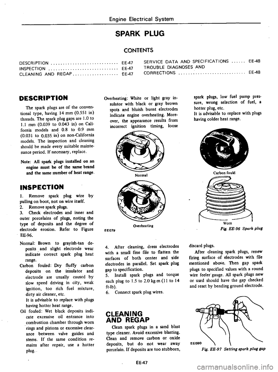
Brown
to
grayish
tan
de
posits
and
slight
electrode
wear
indicate
correct
spark
plug
heat
range
Carbon
fouled
Dry
fluffy
carbon
deposits
on
the
insulator
and
electrode
are
usually
caused
by
slow
speed
driving
in
city
weak
ignition
too
rich
fuel
mixture
dirty
air
cleaner
etc
It
is
advisable
to
replace
with
plugs
having
hotter
heat
range
Oil
fouled
Wet
black
deposits
indi
cate
excessive
oil
entrance
into
combustion
chamber
through
worn
rings
and
pistons
or
excessive
clear
ance
between
valve
guides
and
stems
If
the
same
condition
re
mains
after
repair
use
a
hotter
plug
Engine
Electrical
System
SPARK
PLUG
CONTENTS
EE
4B
EE
47
EE
47
EE
47
SERVICE
DATA
AND
SPECIFICATIONS
TROUBLE
DIAGNOSES
AND
CORRECTIONS
EE
4B
Overheating
White
or
light
gray
in
sulator
with
black
or
gray
brown
spots
and
bluish
burnt
electrodes
indicate
engine
overheating
More
over
the
appearance
results
from
incorrect
ignition
timing
loose
Normal
Overheating
EE079
4
After
cleaning
dress
electrodes
with
a
smaU
fine
file
to
flatten
the
surfaces
of
both
center
and
side
electwdes
in
parallel
Set
spark
plug
gap
to
specification
5
InstaU
spark
plugs
and
torque
each
plug
to
L5
to
2
0
kg
m
11
to
14
ft
Ib
6
Connect
spark
plug
wires
CLEANING
AND
REGAP
Clean
spark
plugs
in
a
sand
blast
type
cleaner
Avoid
excessive
blasting
Clean
and
remove
carbon
or
oxide
deposits
but
do
not
wear
away
porcelain
If
deposits
are
too
stubborn
EE
47
spark
plugs
low
fuel
pump
pres
sure
wrong
selection
of
fuel
a
hotter
plug
etc
It
is
advisable
to
replace
with
plugs
having
colder
heat
range
Ir
i
Carbon
fould
Worn
Fig
EE
96
Spark
plug
discard
plugs
After
cleaning
spark
plugs
renew
firing
surface
of
electrodes
with
me
mentioned
aboVe
Then
gap
spark
plugs
to
specified
values
with
a
round
wire
feeler
gauge
All
spark
plugs
new
or
used
should
have
the
gap
checked
and
reset
by
bending
ground
electrode
EEOBO
Fig
EE
97
Setting
park
plug
gap
Page 231 of 537
CLUTCH
TROUBLE
DIAGNOSES
AND
CORRECTIONS
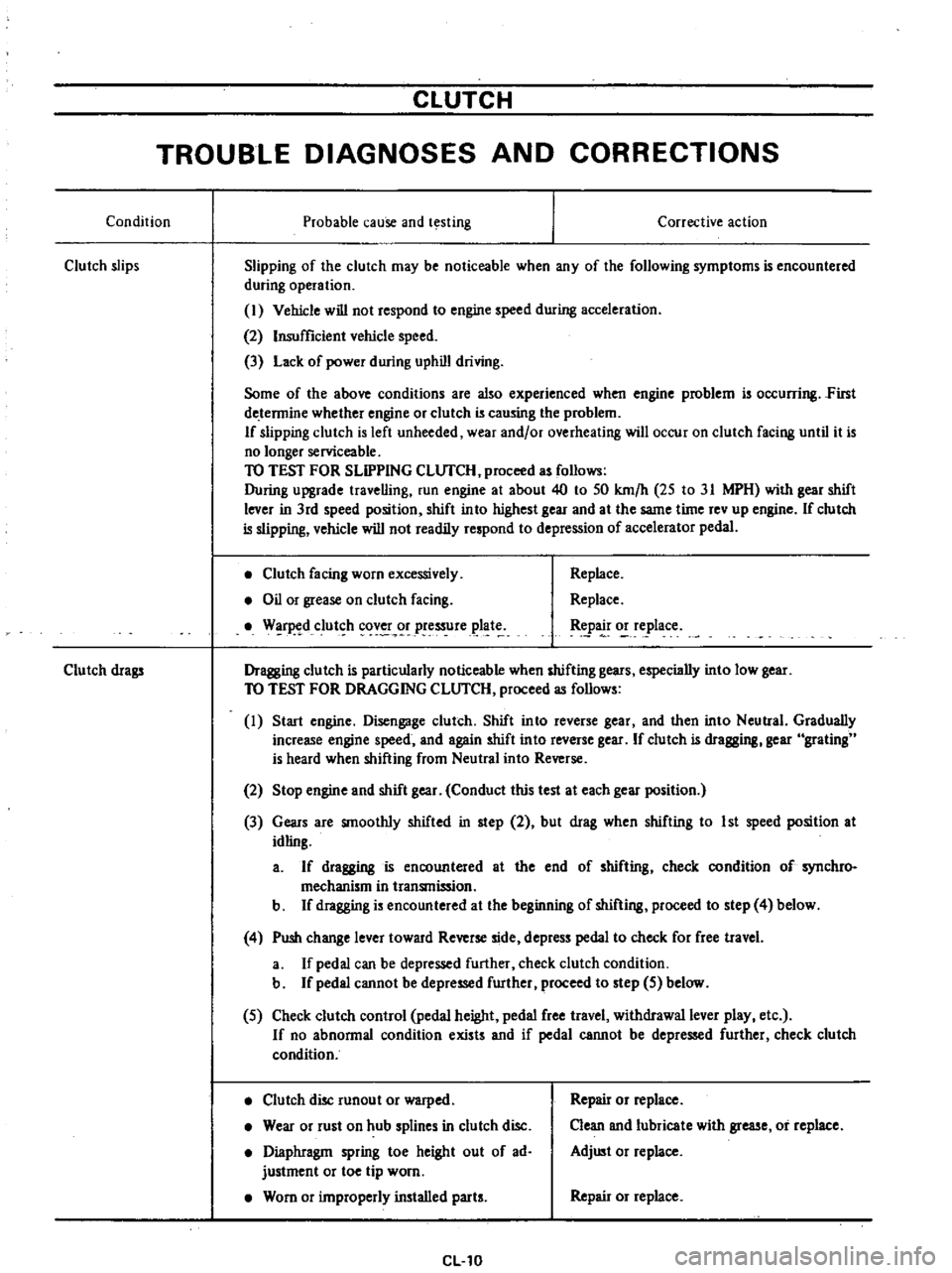
Condition
Probable
cause
and
testing
Clutch
slips
Corrective
action
Slipping
of
the
clutch
may
be
noticeable
when
any
of
the
following
symptoms
is
encountered
during
operation
I
Vehicle
will
not
respond
to
engine
speed
during
acceleration
2
Insufficient
vehicle
speed
3
Lack
of
power
during
uphill
driving
Some
of
the
above
conditions
are
also
experienced
when
engine
problem
is
oc
urring
First
de
tennine
whether
engine
or
clutch
is
causing
the
problem
If
slipping
clutch
is
left
unheeded
wear
and
or
overheating
will
occur
on
clutch
facing
until
it
is
no
longer
serviceable
TO
TEST
FOR
SLIPPING
CLlJfCH
proceed
as
follows
During
upgrade
travelling
run
engine
at
about
40
to
50
km
h
25
to
31
MPH
with
gear
shift
lever
in
3rd
speed
position
shift
into
highest
gear
and
at
the
same
time
rev
up
engine
If
clutch
is
slipping
vehicle
will
not
readily
respond
to
depression
of
accelerator
pedal
Clutch
facing
worn
excessively
Oil
or
grease
on
clutch
facing
W
r
d
clut
h
cov
r
pressure
plat
Replace
Replace
tpa
o
e
lace
Dragging
clutch
is
particularly
noticeable
when
shifting
gears
especially
into
low
gear
TO
TEST
FOR
DRAGGING
CLlJfCH
proceed
as
follows
I
Start
engine
Disengage
clutch
Shift
into
reverse
gear
and
then
into
Neutral
Gradually
increase
engine
speed
and
again
shift
into
reverse
gear
If
clutch
is
dragging
gear
grating
is
heard
when
shifting
from
Neutral
into
Reverse
Clutch
drags
2
Stop
engine
and
shift
gear
Conduct
this
test
at
each
gear
position
3
Gears
are
smoothly
shifted
in
step
2
but
drag
when
shifting
to
1st
speed
position
at
idling
a
If
dragging
is
encountered
at
the
end
of
shifting
check
condition
of
synchro
mechanism
in
transmission
b
If
dragging
is
encountered
at
the
beginning
of
shifting
proceed
to
step
4
below
4
Push
change
lever
toward
Reverse
side
depress
pedal
to
check
for
free
travel
a
If
pedal
can
be
depressed
further
check
clutch
condition
b
If
pedal
cannot
be
depressed
further
proceed
to
step
5
below
5
Check
clutch
control
pedal
height
pedal
free
travel
withdrawal
lever
play
etc
If
no
abnonnal
condition
exists
and
if
pedal
cannot
be
depressed
further
check
clutch
condition
Clutch
disc
runout
or
warped
Wear
or
rust
on
hub
splines
in
clutch
disc
Diaphragm
spring
toe
height
out
of
ad
justment
or
toe
tip
worn
Worn
or
improperly
installed
parts
CL10
Repair
or
replace
Clean
and
lubricate
with
grease
or
replace
Adjust
or
replace
Repair
or
replace
Page 320 of 537
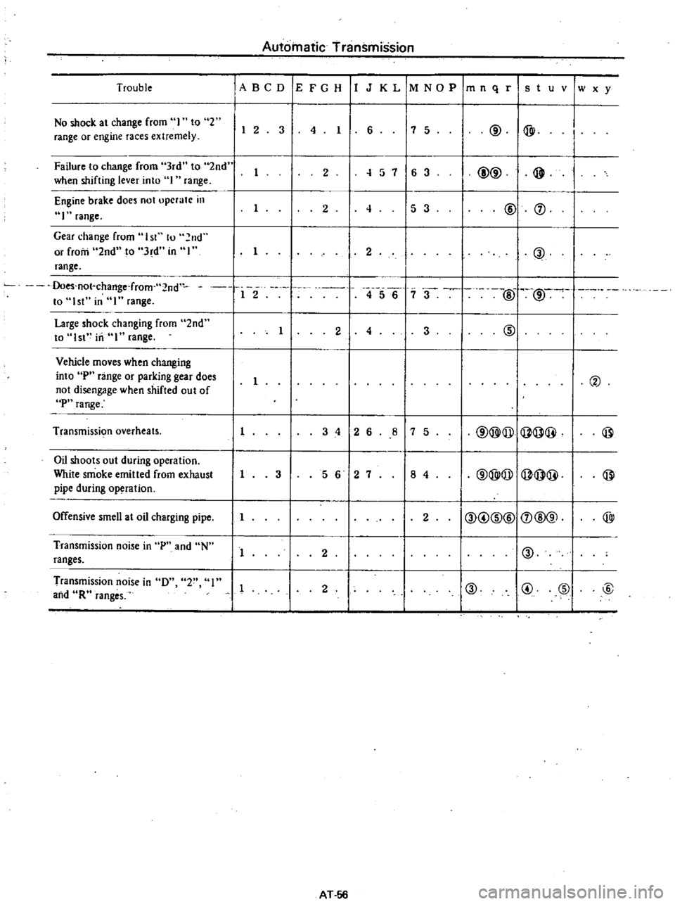
Trouble
No
shock
at
change
from
I
to
2
range
or
engine
races
extremely
Failure
to
change
from
3rd
to
2nd
when
shifting
lever
into
I
range
Engine
brake
does
not
upcrate
in
1
range
Gear
change
frum
I
sr
lu
2nd
or
from
2nd
to
3rd
in
I
range
Does
not
change
f
rom
2nd
to
1st
in
range
Large
shock
changing
from
2nd
to
1st
in
range
Vehicle
moves
when
changing
into
P
range
or
parking
gear
does
not
disengage
when
shifted
out
of
P
range
Transmissic
m
overheats
Oil
shoots
out
during
operation
White
smoke
emitted
from
exhaust
pipe
during
operation
Offensive
smell
at
oil
charging
pipe
Transmission
noise
in
p
and
N
ranges
Transmission
noise
in
D
2
I
and
R
ranges
Automatic
Transmission
ABeD
E
F
G
H
I
J
K
L
1M
NO
P
1m
n
q
r
s
t
u
v
Iw
x
y
6
7
5
@
@
I
I
2
3
4
I
I
2
1
57
6
3
@@
@
I
2
4
5
3
@
f
1
2
@
1
2
4567
3
@
2
1
3
@
2
4
I
2
I
3
4
2
6
8
7
5
@@@
Q
@@
@
I
3
5
6
2
7
8
4
@@@
Q
@@
@
1
2
O
G
@@
f
@@
@
1
2
10
I
I
2
0
G
@
@
AT
56
Page 321 of 537

Automatic
Transmission
TROUBLE
SHOOTING
GUIDE
FOR
3N71B
AUTOMATIC
TRANSMISSION
Order
Test
item
Checking
Oil
level
gauge
2
Downshift
solenoid
3
Manuallinkage
L
4
Inhibitor
switch
5
Engine
idling
rpm
6
Vacuum
pressure
of
vacuum
pipe
7
Operation
in
each
range
8
Creep
of
vehicle
Stall
test
I
Oil
pressure
before
tesling
1
2
Stall
test
3
Oil
pressure
after
testing
Road
test
Slow
acceleration
I
st
2nd
2nd
3rd
2
Quick
acceleration
lst
2nd
2nd
3rd
3
Kick
down
operation
3rd
2nd
or
2nd
1st
Procedure
Check
gauge
for
oil
level
and
leakage
before
and
after
each
test
Check
for
sound
of
operating
solenoid
when
depressing
accelerator
pedal
fully
with
ignition
key
ON
Check
by
shifting
into
P
lR
IN
D
2
and
I
ranges
with
selector
lever
Check
whether
starter
operates
in
N
and
p
ranges
only
and
whether
reverse
lamp
operates
in
R
range
only
Check
whelher
idling
rpm
meet
standard
Check
whether
vacuum
pressure
is
more
than
450
mmHg
in
idling
and
whether
it
decreases
with
increasing
rpm
Check
whether
transmission
engages
positively
by
shifting
N
0
N
2
N
l
I
and
N
R
range
while
idling
with
brake
applied
Check
whether
there
is
any
creep
in
D
2
R
ranges
and
Measure
line
pressures
in
D
2
I
and
R
range
while
idling
Measure
engine
rpm
and
line
pressure
in
D
2
I
and
R
ranges
during
full
throttle
operati
n
Notes
a
Temperature
of
torque
converter
oil
used
in
test
should
be
from
600
to
1000C
1400
to
2120F
i
e
sufficiently
warmed
up
but
not
overheated
b
To
cool
oil
between
each
stall
test
for
D
2
I
and
R
ranges
idle
engine
i
e
rpm
at
about
1
200
rpm
for
more
than
1
minute
in
P
range
Measurement
time
must
not
be
more
than
5
seconds
Same
as
item
I
Check
vehide
speeds
and
engine
cpm
in
shifting
up
Ist
2nd
range
and
2nd
Jo3rd
range
while
running
with
lever
in
D
range
and
engine
vacuum
pressure
of
about
200
I11I1lHg
Same
as
item
1
above
except
with
engine
vacuum
pressure
of
0
mmHg
i
e
in
position
just
before
kickdown
Check
whether
the
kickdown
operates
and
measure
the
time
delays
while
running
at
30
40
50
60
70
km
h
18
25
30
37
43
MPH
in
D3
range
AT
57