battery DATSUN PICK-UP 1977 Service Manual
[x] Cancel search | Manufacturer: DATSUN, Model Year: 1977, Model line: PICK-UP, Model: DATSUN PICK-UP 1977Pages: 537, PDF Size: 35.48 MB
Page 21 of 537
Yellow
line
Spark
delay
valve
to
distributor
Spark
delay
valve
to
vacuum
tube
Distributor
to
vacuum
tube
Vacuum
tube
to
carburetor
Vacuum
tube
to
canister
Green
line
Anti
backfire
valve
to
intake
mani
fold
Air
control
valve
to
emergency
air
relief
valve
Intake
manifold
to
vacuum
hose
connector
Intake
manifold
to
canister
CHECKING
ENGINE
COMPRESSION
COMPRESSION
PRESSURE
TEST
I
Warm
up
engine
sufficiently
2
Disconnect
all
spark
plugs
3
Disconnect
anti
dieseling
solenoid
valve
connector
4
Properly
attach
a
compression
tester
to
spark
plug
hole
in
cylinder
being
tested
Engine
Tune
up
I
ET010
Different
compression
in
two
or
more
cylinders
usually
indicates
an
improperly
seated
valve
or
broken
piston
ring
9
Low
compression
in
cylinders
can
result
from
worn
piston
rings
This
condition
may
usually
be
accompanied
by
excessive
fuel
consumption
TEST
RESULT
If
compression
in
one
or
more
cylinders
is
low
pour
a
small
quantity
of
engine
oil
into
cylinders
through
the
spark
plug
holes
and
retest
com
pression
I
If
adding
oil
increases
the
com
pression
pressure
the
chances
are
that
rings
are
faulty
2
If
pressure
stays
low
probable
cause
is
that
valve
is
sticking
or
seating
improperly
3
If
cylinder
compression
in
any
two
adjacent
cylinders
is
low
and
if
adding
oil
does
not
help
the
compres
sian
there
is
leakage
past
the
gasket
surface
Oil
and
water
in
combustion
cham
bers
can
result
from
leakage
IGNITION
AND
FUEL
SYSTEM
Fig
ET
10
Teding
compression
pressure
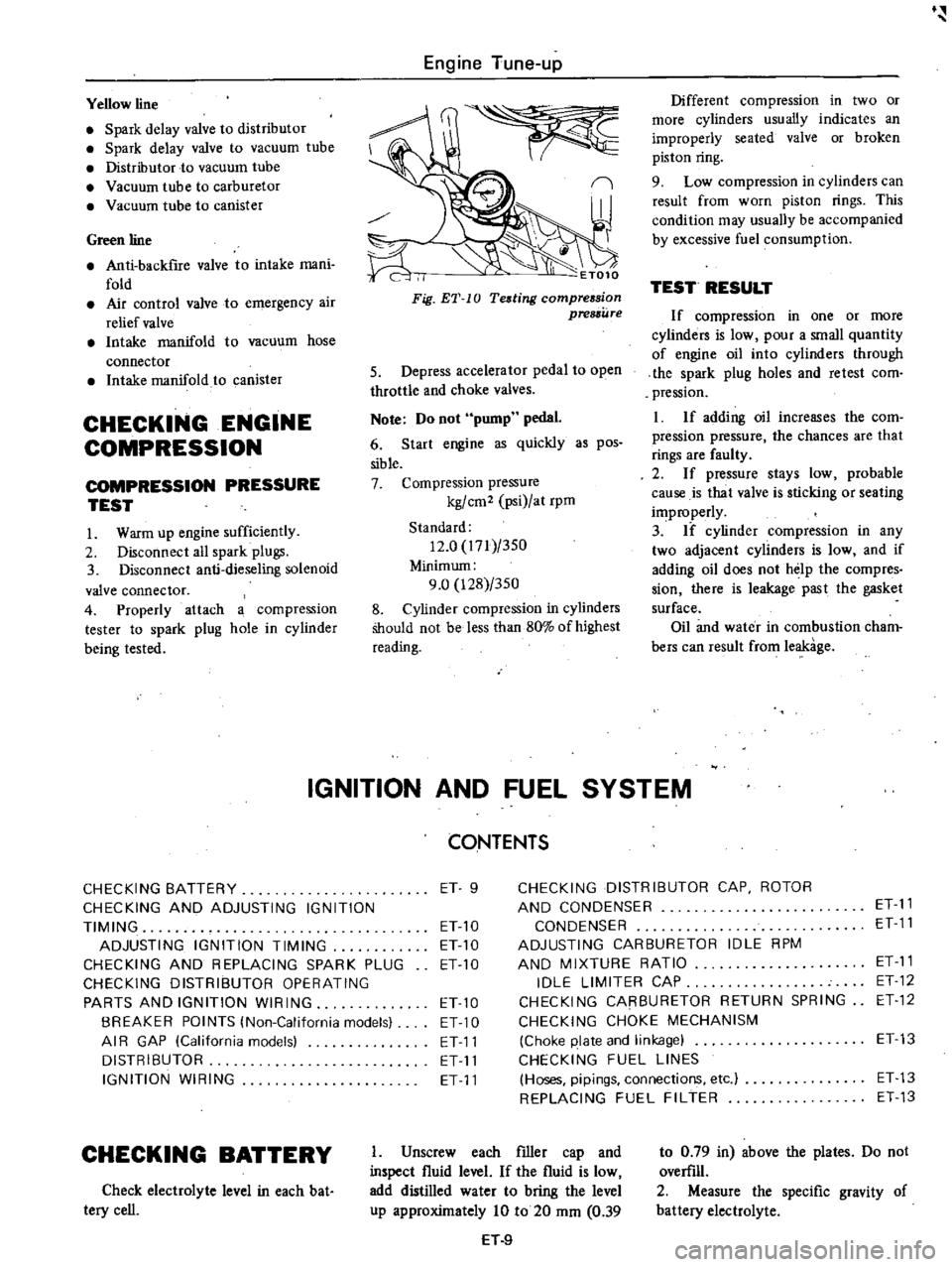
5
Depress
accelerator
pedal
to
open
throttle
and
choke
valves
Note
Do
not
pump
pedal
6
Start
engine
as
quickly
as
pos
sible
7
Compression
pressure
kg
cm2
psi
at
rpm
Standard
12
0
171
350
Minimum
9
0
128
350
8
Cylinder
compression
in
cylinders
Should
not
be
less
than
80
of
highest
reading
CONTENTS
CHECKING
BATTERY
ET
9
CHECKING
DISTRIBUTOR
CAP
ROTOR
CHECKING
AND
ADJUSTING
IGNITION
AND
CONDENSER
ET
11
TIMING
ET
10
CONDENSER
ET
11
ADJUSTING
IGNITION
TIMING
ET10
ADJUSTING
CARBURETOR
IDLE
RPM
CHECKING
AND
REPLACING
SPARK
PLUG
ETlO
AND
MIXTURE
RATIO
ET
11
CHECKING
DISTRIBUTOR
OPERATING
IDLE
LIMITER
CAP
ET
12
PARTS
AND
IGNITION
WIRING
ETlO
CHECKING
CARBURETOR
RETURN
SPRING
ET
12
BREAKER
POINTS
lNon
California
models
ET
10
CHECKING
CHOKE
MECHANISM
AI
R
GAP
lCalifornia
models
ET11
Choke
plate
and
linkage
ET13
DISTRIBUTOR
ET
11
CHECKING
FUEL
LINES
IGNITION
WIRING
ET
11
Hoses
pipings
connections
etc
ET
13
REPLACING
FUEL
FILTER
ET
13
CHECKING
BATTERY
Check
electrolyte
level
in
each
bat
tery
cell
I
Unscrew
each
filler
cap
and
inspect
fluid
level
If
the
fluid
is
low
add
distilled
water
to
bring
the
level
up
approximately
10
to
20
mm
0
39
H
9
to
0
79
in
above
the
plates
Do
not
overfill
2
Measure
the
specific
gravity
of
battery
electrolyte
Page 22 of 537
p
r
ET002
Fig
E1
11
Checking
specific
gravity
of
bottery
electrolyre
Clean
top
of
battery
and
terminals
with
a
solution
of
bakin
soda
and
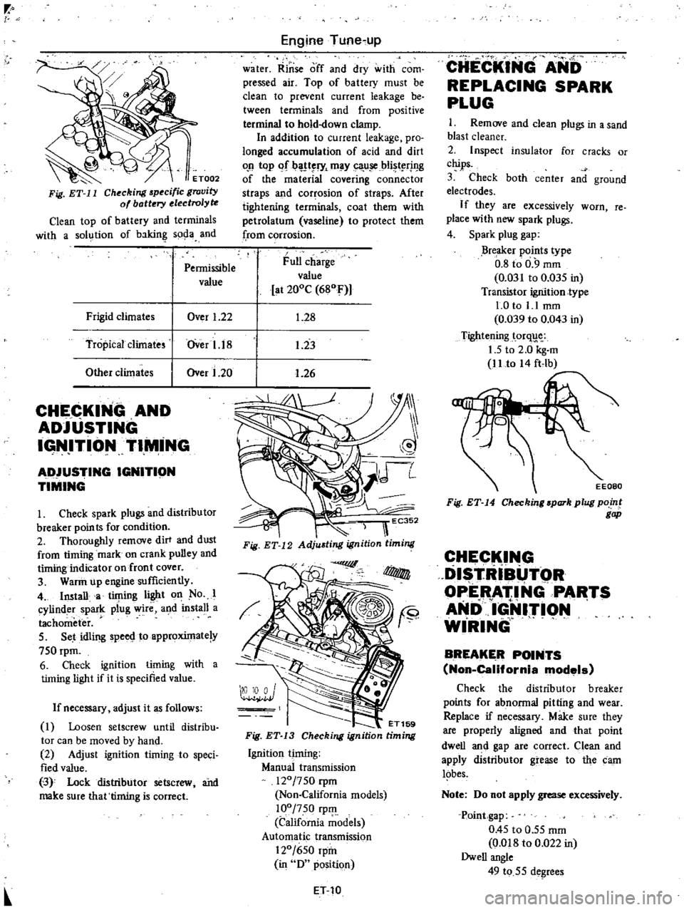
Pennissible
value
Frigid
climates
Over
1
22
Tropical
climates
lOver
1
18
Other
climates
lOver
1
20
CHECKING
AND
ADJUSTING
IGN
ITIONTIM
iNG
AD
IUSTING
IGNITION
TIMING
I
Check
spark
plugs
and
distributor
breaker
points
for
condition
2
Thoroughly
remove
dirt
and
dust
from
timing
mark
on
crank
pulley
and
timing
indicator
on
front
cover
3
Warin
up
engine
sufficiently
4
Imtalla
timing
light
on
No
I
cylinder
spark
plug
wire
and
install
a
tachometer
5
Set
idling
spero
toapproxintate
y
750
rpm
6
Check
ignition
timing
with
a
timing
light
if
it
is
specified
value
If
necessary
adjust
it
as
follows
1
Loosen
setscrew
until
distribu
tor
can
be
moved
by
hand
2
Adjust
ignition
timing
to
speci
fied
value
3
0
Lock
distributor
setscrew
ai1d
make
sure
that
timing
is
correc
Engine
Tune
up
water
Rinse
off
and
dry
with
com
pressed
air
Top
of
battery
must
be
clean
to
prevent
current
leakage
be
tween
terminals
and
from
positive
terminal
to
hold
down
clamp
In
addition
to
current
leakage
pro
longed
accumulation
of
acid
and
dirt
o
n
top
If
l
l
ry
may
ca
u
iCbli
t
rj
I
g
of
the
material
covering
connector
straps
and
corrosion
of
straps
After
tightening
terminals
coat
them
with
petrolatum
vaseline
to
protect
them
from
corrosion
Full
charge
value
at
200C
680F
1
28
1
23
1
26
oo
I
ET169
Fig
ET
13
Checking
ignition
timing
Ignition
timing
Manual
transmission
120
750
rpm
Non
California
models
100
750
rpIll
California
models
Automatic
transmission
120
650
rpin
in
0
position
ET
10
CHECKING
ANb
REPLACING
SPARK
PLUG
I
Remove
and
clean
plugs
in
a
sand
blast
cleaner
2
Inspect
insulator
for
cracks
or
chips
3
Check
both
center
and
ground
electrodes
If
they
are
excessively
worn
re
place
with
new
spark
plugs
4
Spark
plug
gap
Breaker
points
type
0
8
to
0
9
mm
0
031
to
0
035
in
Transistor
ignition
type
1
0
to
1
1
mm
0
039
to
0
043
in
Tightening
torq
1
5
to
2
0
kg
m
11
to
A4
ft
lb
Fig
ET
14
Checking
spark
plug
point
gap
CHECK
I
G
DISTRIBUTOR
OPERATING
PARTS
AND
1
lrI9N
WIRING
BREAKER
POINTS
Non
California
models
Check
the
distributor
breaker
points
for
abnonnal
pitting
and
wear
Replace
if
necessary
Make
sure
they
are
properly
aligned
and
that
point
dwell
and
gap
are
correct
Clean
and
apply
distributor
grease
to
the
carn
lobes
Note
00
not
apply
grease
excessively
Point
gap
0
45
to
0
55
mm
Om8
to
0
022
in
Owell
angle
49
to
55
degrees
Page 37 of 537
Engine
Tune
up
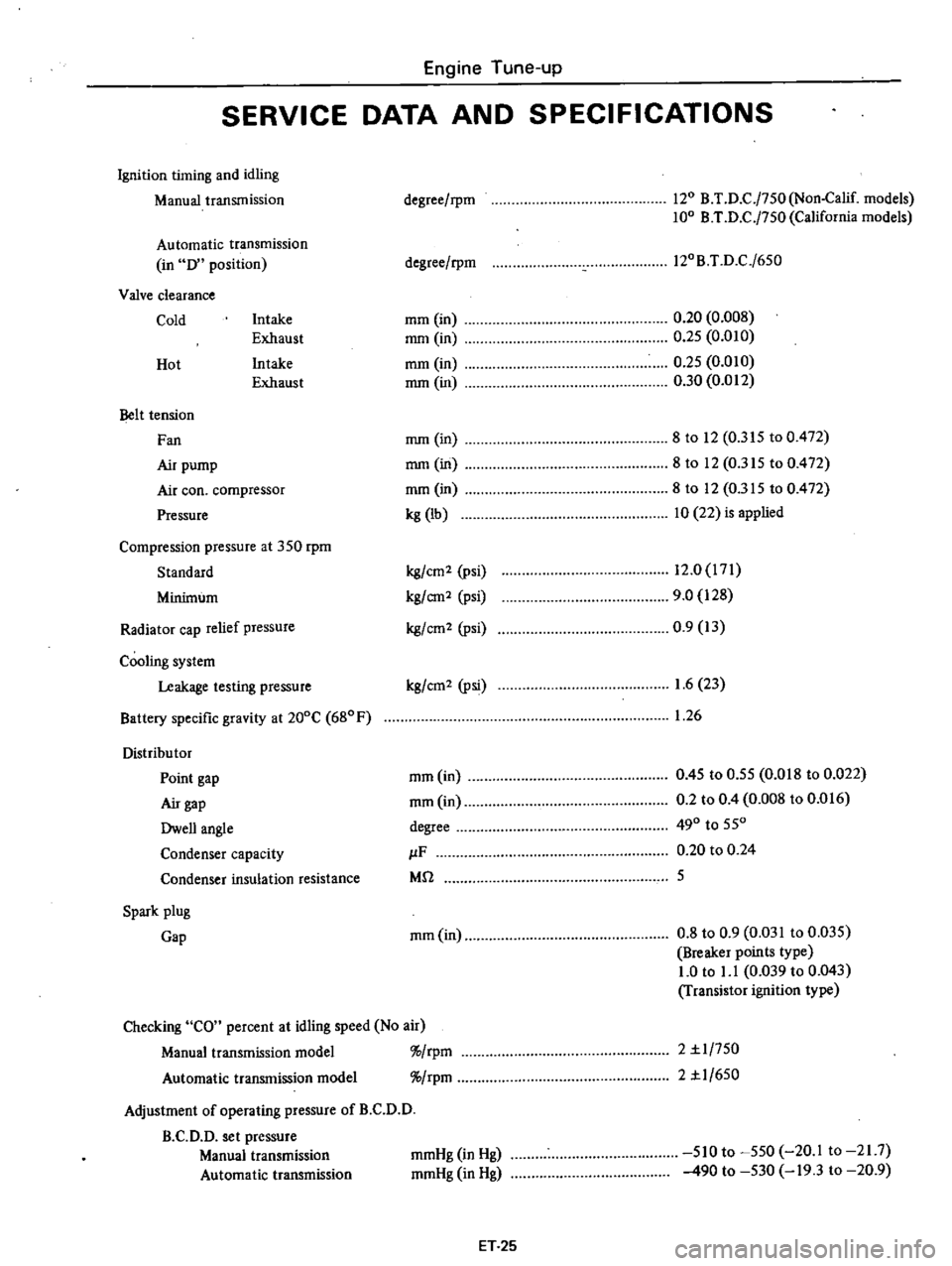
SERVICE
DATA
AND
SPECIFICATIONS
Ignition
timing
and
idling
Manual
transmission
Automatic
transmission
in
D
position
Valve
clearance
Cold
Intake
Exhaust
Intake
Exhaust
Hot
Belt
tension
Fan
Air
pump
Air
coo
compressor
Pressure
Compression
pressure
at
350
rpm
Standard
Minimum
Radiator
cap
relief
pressure
Cooling
system
Leakage
testing
pressure
Battery
specific
gravity
at
200C
680F
Distribu
tor
Point
gap
Air
gap
Dwell
angle
Condenser
capacity
Condenser
insulation
resistance
Spark
plug
Gap
degree
rpm
120
B
T
D
C
j750
Non
Calif
models
100
B
T
D
C
j750
California
models
degree
rpm
l20B
T
D
C
j650
mm
in
mm
in
mm
in
mm
in
0
20
0
008
0
25
0
010
0
25
0
010
0
30
0
012
mm
in
mm
in
mm
in
kg
lb
8
to
12
0
315
to
0
472
8to
12
0
315
to
0
472
8
to
12
0
315
to
0
472
10
22
is
applied
kg
cm2
psi
kg
em2
psi
kg
em
2
psi
12
0
171
9
0
128
0
9
13
kg
cm2
Psi
1
6
23
1
26
mm
in
mm
in
degree
IF
Mil
0
45
to
0
55
0
018
to
0
022
0
2
to
0
4
0
008
to
0
016
490
to
550
0
20
to
0
24
5
mm
in
0
8
to
0
9
0
031
to
0
035
Breaker
points
type
1
0
to
1
1
0
039
to
0
043
Transistor
ignition
type
Checking
CO
percent
at
idling
speed
No
air
Manual
transmission
model
rpm
Automatic
transmission
model
rpm
Adjustment
of
operating
pressure
of
B
C
D
D
B
C
D
D
set
pressure
Manual
transmission
Automatic
transmission
2
1
1
750
2
1
1
650
mmHg
in
Hg
mmHg
in
Hg
510
to
550
20
1
to
21
7
490
to
530
19
3
to
20
9
ET
25
Page 39 of 537

Engine
Tune
up
TROUBLE
DIAGNOSES
AND
CORRECTIONS
Condition
Probable
cause
CANNOT
CRANK
ENGINE
OR
SLOW
CRANKING
Improper
grade
oil
Discharged
battery
Faulty
battery
Loose
fan
belt
Malfunction
in
charge
system
Wiring
connection
loose
in
starting
circuit
Faulty
ignition
switch
Faulty
starler
motor
Trouble
shooting
procedure
on
starting
circuit
Switch
on
the
starting
motor
with
light
ON
When
light
goes
off
or
dims
considerably
a
Check
battery
b
Check
connection
and
cable
c
Check
starter
motor
When
light
stays
bright
Corrective
action
Replace
with
proper
grade
oiL
Charge
battery
Replace
Adjust
Inspect
Correct
Repair
or
replace
Repair
or
replace
a
Check
wiring
connection
between
battery
and
starter
motor
b
Check
ignition
switch
c
Check
starter
motor
ENGINE
WILL
CRANK
NORMALLY
BUT
WILL
NOT
START
In
this
case
the
following
trouble
causes
may
exist
but
in
many
cases
ignition
system
or
fuel
system
is
in
trouble
Ignition
system
in
trouble
Fuel
system
in
troubk
Valve
mechanism
does
not
work
properly
Low
compussion
Trouble
shooting
procedure
Check
spark
plug
firstly
by
following
procedure
Disconnect
high
tension
cable
from
one
spark
plug
and
hold
it
about
10
mm
0
39
in
from
the
engine
metal
part
and
crank
the
engine
Good
spark
occurs
Check
spark
plug
b
Check
ignition
timing
c
Check
fuel
system
d
Check
cylinder
compression
Check
the
current
f10
in
primary
circuit
Very
high
current
Inspect
primary
circuit
for
short
Check
breaker
poiIit
operation
except
tran
sistor
ignition
system
No
spark
occurs
ET
27
Page 108 of 537

854
co
in
in
one
minute
or
less
If
no
gasoline
or
only
a
little
flows
from
open
end
of
pipe
with
pump
operated
or
if
pump
does
not
work
perform
the
following
diagnosis
Notes
3
Do
not
connect
battery
in
reverse
polarity
which
if
left
for
a
long
time
would
damage
transitor
circuit
and
disable
pump
Engine
Fuel
b
Do
not
let
fall
pump
as
it
may
damage
electronic
components
c
Do
not
apply
overvoitage
max
l
8Y
Overvoltage
starting
by
quick
charge
or
tage
running
would
deteriorate
or
damage
elec
tronic
components
Fuel
pressure
maximum
0
32
kg
cm
4
6
psi
REMOVAL
AND
INSTALLATION
Flom
fuel
tank
Electric
fuel
pump
is
installed
on
bracket
with
two
bolts
This
bracket
is
located
on
R
H
side
member
adjacent
to
fuel
tank
I
Remove
inlet
hose
from
fuel
pump
Also
remove
outlet
hose
run
ning
to
engine
Receive
fuel
remaining
in
fuel
hose
in
a
suitable
container
2
Disconnect
harness
at
connector
3
Remove
bolts
securing
fuel
pump
to
bracket
and
detach
fuel
pump
4
Installation
is
the
reverse
order
of
removal
9
@
1
Cover
2
Magnet
3
Cover
gasket
4
Filter
5
Gasket
6
Spring
retainer
7
Washer
8
O
ring
9
Inlet
valve
10
Retutn
PIing
11
Plunger
12
Plunger
cylinder
13
Body
To
carburetor
1
Elecuic
fuel
pump
2
Mounting
bracket
3
Fuel
mter
EF72D
Fig
EF
23
Electric
fuel
pump
DISASSEMBLY
Do
not
disassemble
unless
pump
is
faulty
I
Remove
cover
with
wrench
and
take
out
cover
gasket
magnet
and
filter
from
pump
body
2
When
removing
plunger
take
out
spring
retainer
from
plunger
tube
3
Then
take
out
washer
O
ring
inlet
valve
return
spring
and
plunger
from
tube
Note
Do
not
disassemble
electronic
components
If
n
replace
with
new
ones
6
EF721
Fig
EF
24
Exploded
view
of
electric
fuel
pump
EF
12
ASSEMBLY
I
Before
assembly
clean
all
parts
with
gasoline
and
compressed
air
com
pletely
Notes
a
If
gask
t
an
d
fdterare
faulty
r
place
b
Clean
magnet
and
cover
for
fault
c
Take
care
not
to
defonn
thin
tube
d
Assemble
plunger
return
spring
inlet
valve
O
ring
washer
and
set
spring
retainer
in
that
order
e
Assemble
filter
gasket
and
cover
with
f
Tighten
cover
with
wrench
to
the
stopper
If
component
parts
are
dirty
after
disassembly
clean
as
follows
Wash
fIlter
and
strainer
with
clean
gasoline
and
blow
with
compressed
air
When
cleaning
parts
check
fllter
for
fault
If
faulty
replace
Wash
plunger
plunger
cylinder
and
inlet
valve
with
clean
gasoline
and
blow
dust
off
with
compressed
air
2
Check
c
v
m
lI
parts
for
wear
or
damage
If
they
are
found
faulty
replace
them
3
Insert
plunger
assembly
into
plunger
cylinder
of
body
and
apply
electric
current
to
it
Move
the
assembly
up
and
down
If
the
assembly
does
not
move
it
shows
that
the
electric
uuit
is
faulty
and
it
must
be
replaced
Page 113 of 537
Step
system
The
construction
of
this
system
may
correspond
to
the
idling
and
slow
system
of
the
primary
system
Tlris
system
aims
at
the
proper
filling
up
of
the
gap
when
fuel
supply
is
transferred
from
the
primary
system
to
the
secondary
one
The
step
port
is
located
near
the
secondary
throttle
valve
edge
in
its
fully
closed
state
Secondary
switchover
mechanism
The
secondary
throttle
valve
is
linked
to
the
diaphragm
which
is
actuated
by
the
vacuum
created
in
the
venturi
A
vacuum
jet
is
provided
at
each
of
the
primary
and
secondary
venturies
and
the
composite
vacuum
of
these
jets
actuates
the
diaphragm
As
the
linkage
causes
the
secondary
throttle
valve
to
close
until
the
prima
ry
throttle
valve
opening
reaches
ap
proximately
500
fuel
consumption
during
normal
operation
is
not
exces
sive
During
high
speed
running
as
shown
in
Figure
EF
28
as
the
vacuum
at
the
venturi
is
increased
the
dia
phragm
is
pulled
against
the
diaphragm
spring
force
and
then
secondary
throt
tie
valve
is
opened
The
other
side
during
low
speed
running
as
the
primary
throttle
valve
opening
does
not
reach
500
the
secondary
throttle
valve
is
locked
to
close
completely
by
the
locking
arm
which
is
interlocked
with
primary
throttle
arm
by
linkage
When
the
primary
throttle
valve
opening
reaches
wider
position
than
500
the
secondary
throttle
valve
is
ready
to
open
because
the
locking
arm
revolves
and
leaves
from
the
se
condary
throttle
arm
Engine
Fuel
HI
h
speed
circuit
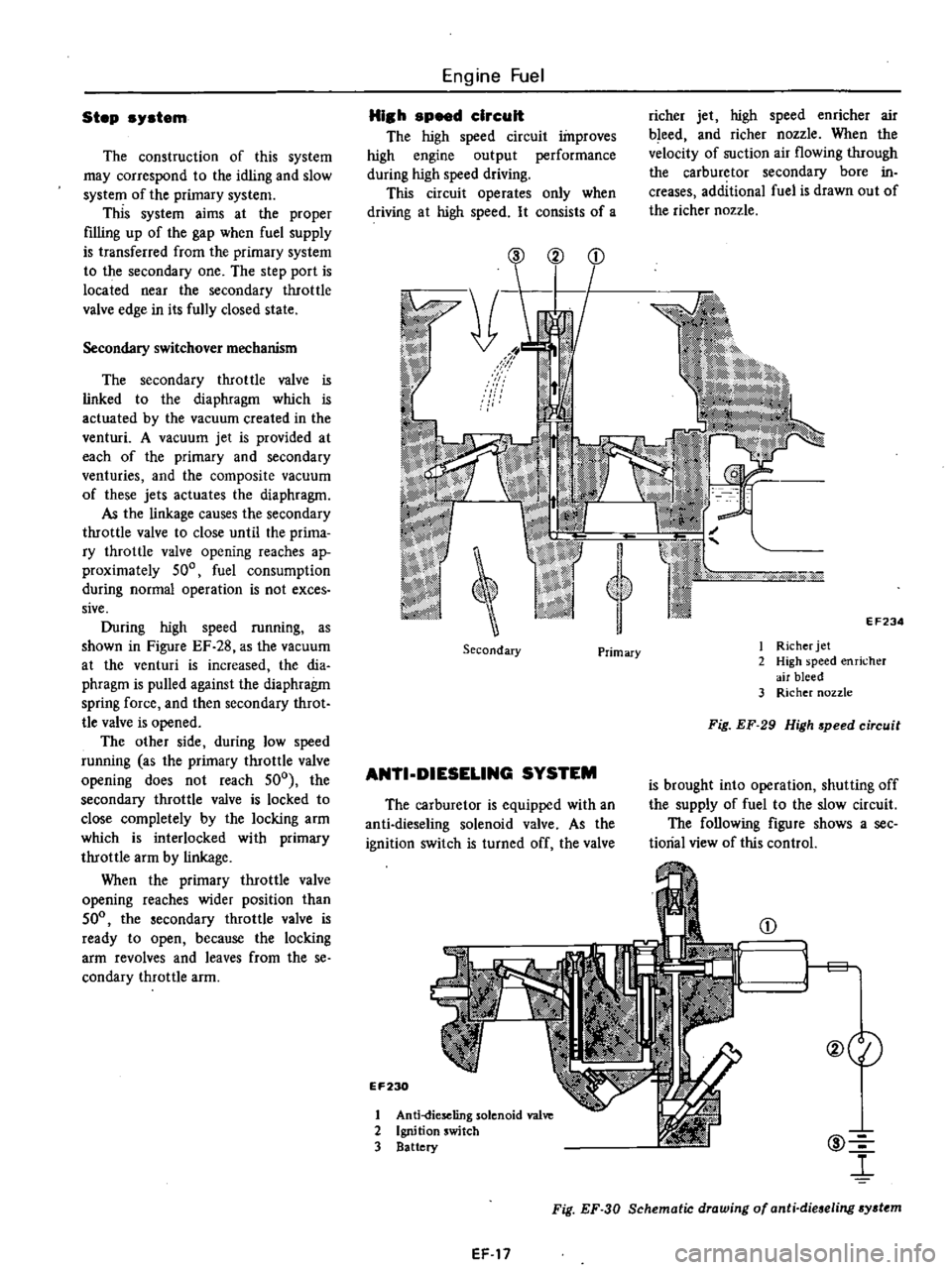
The
high
speed
circuit
improves
high
engine
output
performance
during
high
speed
driving
This
circuit
operates
only
when
driving
at
high
speed
It
consists
of
a
richer
jet
high
speed
enricher
air
bleed
and
richer
nozzle
When
the
velocity
of
suction
air
flowing
through
the
carburetor
secondary
bore
in
creases
additional
fuel
is
drawn
out
of
the
richer
nozzle
@
2
EF234
Secondary
I
Richer
jet
2
High
speed
enricher
air
bleed
3
Richer
nozzle
Primary
Fig
EF
29
High
speed
circuit
ANTI
DIESELlNG
SYSTEM
is
brought
into
operation
shutting
off
the
supply
of
fuel
to
the
slow
circuit
The
following
figure
shows
a
see
tiorial
view
of
this
control
The
carburetor
is
equipped
with
an
anti
dieseling
solenoid
valve
As
the
ignition
switch
is
turned
off
the
valve
EF230
@
l
CD
1
1
g
@eI
1
Anti
dieseling
solenoid
va1
2
Ignition
switch
3
Battery
Fig
EF
30
Schematic
drawing
of
anti
dieseling
sydtm
EF
17
Page 161 of 537
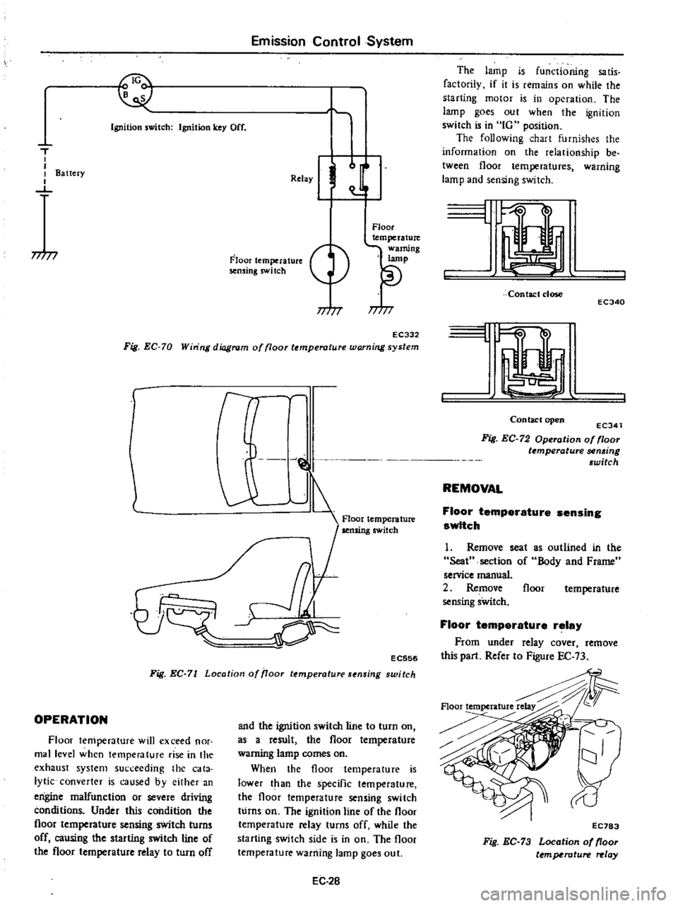
I
Emission
Control
System
Ignition
switch
Ignition
key
Off
T
I
I
I
Battery
I
J
77
77
Relay
J
Floor
temperature
sensing
swi
tch
Floor
temperature
warning
lamp
77
77
EC332
Fig
EC
70
Win
ng
diagram
of
floor
temperature
warning
system
r
l
J
@
1
Floor
temperature
Ij
cr
EC556
Fig
EC
71
Location
of
iJoor
temperature
sensing
switch
OPERATION
Floor
temperature
will
exceed
nor
mal
level
when
temperature
rise
in
the
exhaust
system
succeeding
the
cata
lytic
converter
is
caused
byeilher
an
engine
malfunction
or
severe
driving
conditions
Under
this
condition
the
floor
temperature
sensing
switch
turns
off
causing
the
starting
switch
line
of
the
floor
temperature
relay
to
turn
off
and
the
ignition
switch
line
to
turn
on
as
a
result
the
floor
temperature
warning
lamp
comes
on
When
the
floor
temperature
is
lower
t
an
the
specific
temperature
the
floor
temperature
sensing
switch
turns
on
The
ignition
line
of
the
floor
temperature
relay
turns
off
while
the
starting
switch
side
is
in
on
The
floor
temperature
warning
lamp
goes
out
EC
2B
The
lamp
is
functioning
sa
tis
factorily
if
it
is
remains
on
while
the
starting
motor
is
in
operation
The
lamp
goes
out
when
the
ignition
switch
is
in
IG
position
The
foUowing
chart
furnishes
the
information
on
the
relationship
be
tween
floor
temperatures
warning
lamp
and
sensing
switch
L
Contact
close
ECJ40
I
Contaclopen
ECJ41
Fig
EC
72
Operation
of
floor
t
mperature
sen6ing
6witch
REMOVAL
Floor
temperature
sensing
switch
1
Remove
seat
Seat
section
of
service
manual
2
Remove
sensing
sWitch
as
outlined
in
the
Body
and
Frame
floor
temperature
Floor
temperature
relay
From
under
relay
cover
remove
this
part
Refer
to
Figure
EC
73
Floortemperature
EC783
Fig
EC
73
Location
of
floor
ttmperature
relay
Page 168 of 537
DATSUN
PICK
UP
MODEL
620
SERIES
I
NISSAN
I
NISSAN
MOTOR
CO
LTD
TOKYO
JAPAN
SECTION
EE
ENGINE
ELECTRICAL
SYSTEM
BATTERY
EE
2
STARTING
MOTOR
EE
4
CHARGING
CIRCUIT
EE
12
ALTERNATOR
EE
15
REGULATOR
EE
20
IGNITION
CIRCUIT
EE
26
DISTRIBUTOR
EE
30
Non
California
models
DISTRIBUTOR
California
models
EE
33
TRANSISTOR
IGNITION
UNIT
California
models
IGNITION
COIL
SPARK
PLUG
EE
36
EE
46
EE
47
Page 169 of 537

REMOVAL
CHECKING
ELECTROLYTE
LEVEL
CHECKING
SPECIFIC
GRAVITY
REMOVAL
I
Disconnect
negative
and
positive
cables
2
Remove
nuts
from
battery
clamps
take
off
clamps
3
Remove
battery
CHECKING
ELECTROLYTE
LEVEL
Remove
six
vent
plugs
and
check
for
electrolyte
level
in
each
cell
If
nccessaJ
pour
distilled
water
CHECKING
SPECIFIC
GRAVITY
Specific
gravity
of
battery
electro
lyte
is
tested
by
a
hydrometer
If
the
srate
of
charge
of
battery
is
60
or
specific
gravity
reading
is
below
1
20
as
corrected
at
200e
680F
bat
tery
must
be
recharged
or
battery
electrolyte
concentration
adjusted
Add
or
subtract
gravity
points
according
to
whether
the
electrolyte
temperature
is
above
or
below
200e
680F
standard
The
gravity
of
electrolyte
chlll
ges
0
0007
for
every
Ioe
1
80F
tem
petature
A
correction
can
then
be
made
by
using
the
following
formula
Engine
Electrical
System
BATTERY
CONTENTS
EE
2
EE
2
EE
2
BATTERY
FREEZING
CHARGING
INST
ALLA
TION
S
20
St
0
0007
t
20
Where
St
Specific
gravity
of
electrolyte
at
tOe
520
Specific
gravity
of
electrolyte
corrected
at
200e
680F
t
Electrolyte
temperature
For
example
A
hydrometer
reading
of
1
260
at
300e
860F
would
be
1
267
corrected
to
200e
6goF
indicating
fully
charged
battery
On
the
other
hand
a
hydro
meter
reading
of
1
220
at
lOoe
140
F
would
be
1
199
corrected
to
200e
680F
indicating
a
partially
charged
battery
The
state
of
charge
of
battery
can
be
determined
by
the
following
table
if
the
specific
gravity
of
electrolyte
is
known
BefOIe
checking
be
sure
that
cells
are
filled
to
correct
level
G
U
o
N
b
t
E
u
ol
1
lilt
I
i
I
m
J
I
I
I
I
J
1
I
J
Sf
to
7
1
II
It
100
0wJIztI
COJJditioD
EE002
Fig
EE
2
ChaJ
ffing
condition
EE
2
1
28
@
126
S
Sow
E
l
l
u
o
o
l
e
u
0
U21
1
101
EE
3
EE
3
EE
3
Read
top
level
with
scale
1
Thermal
gauge
2
Hydrometer
feOOl
Fig
EE
l
Checking
pccme
gravity
Converted
specific
gavity
20
1
Je
I
dOldlOiJ
OSQ
Electrolyte
temperature
oC
EEOO3
Fig
EE
3
Specific
lNWity
at
eiectroly
te
temperature
Page 170 of 537

BATTERY
FREEZING
Battery
electrolyte
freezing
point
varies
with
acid
concentration
or
its
specific
gravity
A
battery
with
an
insufficient
charge
will
freeze
at
lower
temperatures
If
specific
gravity
of
a
battery
falls
below
1
1
this
is
an
0
10
20
30
g
40
I
u
il
SO
I
0
e
60
0
E
70
Engine
Electrical
System
indication
that
battery
is
completely
discharged
and
will
freeze
readily
when
temperatures
fall
below
freezing
Note
Use
extreme
caution
to
avoid
freezing
battery
since
freezing
will
generally
ruin
the
battery
1
80
1
00
1
04
1
08
t
l2
1
16
t
20
1
24
1
28
Specific
gravity
of
electrolyte
CHARGING
I
f
electrolyte
level
is
satisfactory
battery
must
be
charged
when
electro
lyte
gravity
reading
falls
below
1
20
If
battery
on
car
is
quick
charged
to
1
32
EEOQ4
Fig
EE
4
Froezing
point
of
electrolyte
bring
it
up
to
full
charge
the
opera
tion
should
be
carried
out
with
nega
tive
cable
removed
Prior
to
charging
corroded
termi
EE
3
nals
should
be
cleaned
with
a
brush
and
common
baking
soda
solution
In
addition
the
following
items
should
be
observed
while
battery
is
being
charged
I
Be
sure
that
electrolyte
level
is
above
top
of
each
plate
2
Keep
removed
plugs
in
a
safe
place
3
Do
not
allow
electrolyte
tempera
ture
to
go
over
450C
I130F
4
After
charging
check
to
be
cer
tain
that
specific
gravity
does
not
exceed
1
260
at
200C
680P
Cor
rection
can
be
made
by
adding
dis
tilled
water
into
cells
as
necessary
5
Keep
battery
away
from
open
flame
while
it
is
being
charged
6
After
all
vent
plugs
have
been
tightened
clean
all
sprayed
electrolyte
off
upper
face
of
battery
INSTALLATION
1
Install
and
tighten
clamps
secure
Iy
2
After
clamps
have
been
tightened
clean
battery
cable
terminals
and
apply
grease
to
retard
formation
of
corrosion