compression ratio DATSUN PICK-UP 1977 Service Manual
[x] Cancel search | Manufacturer: DATSUN, Model Year: 1977, Model line: PICK-UP, Model: DATSUN PICK-UP 1977Pages: 537, PDF Size: 35.48 MB
Page 21 of 537
Yellow
line
Spark
delay
valve
to
distributor
Spark
delay
valve
to
vacuum
tube
Distributor
to
vacuum
tube
Vacuum
tube
to
carburetor
Vacuum
tube
to
canister
Green
line
Anti
backfire
valve
to
intake
mani
fold
Air
control
valve
to
emergency
air
relief
valve
Intake
manifold
to
vacuum
hose
connector
Intake
manifold
to
canister
CHECKING
ENGINE
COMPRESSION
COMPRESSION
PRESSURE
TEST
I
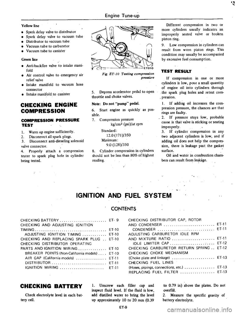
Warm
up
engine
sufficiently
2
Disconnect
all
spark
plugs
3
Disconnect
anti
dieseling
solenoid
valve
connector
4
Properly
attach
a
compression
tester
to
spark
plug
hole
in
cylinder
being
tested
Engine
Tune
up
I
ET010
Different
compression
in
two
or
more
cylinders
usually
indicates
an
improperly
seated
valve
or
broken
piston
ring
9
Low
compression
in
cylinders
can
result
from
worn
piston
rings
This
condition
may
usually
be
accompanied
by
excessive
fuel
consumption
TEST
RESULT
If
compression
in
one
or
more
cylinders
is
low
pour
a
small
quantity
of
engine
oil
into
cylinders
through
the
spark
plug
holes
and
retest
com
pression
I
If
adding
oil
increases
the
com
pression
pressure
the
chances
are
that
rings
are
faulty
2
If
pressure
stays
low
probable
cause
is
that
valve
is
sticking
or
seating
improperly
3
If
cylinder
compression
in
any
two
adjacent
cylinders
is
low
and
if
adding
oil
does
not
help
the
compres
sian
there
is
leakage
past
the
gasket
surface
Oil
and
water
in
combustion
cham
bers
can
result
from
leakage
IGNITION
AND
FUEL
SYSTEM
Fig
ET
10
Teding
compression
pressure
5
Depress
accelerator
pedal
to
open
throttle
and
choke
valves
Note
Do
not
pump
pedal
6
Start
engine
as
quickly
as
pos
sible
7
Compression
pressure
kg
cm2
psi
at
rpm
Standard
12
0
171
350
Minimum
9
0
128
350
8
Cylinder
compression
in
cylinders
Should
not
be
less
than
80
of
highest
reading
CONTENTS
CHECKING
BATTERY
ET
9
CHECKING
DISTRIBUTOR
CAP
ROTOR
CHECKING
AND
ADJUSTING
IGNITION
AND
CONDENSER
ET
11
TIMING
ET
10
CONDENSER
ET
11
ADJUSTING
IGNITION
TIMING
ET10
ADJUSTING
CARBURETOR
IDLE
RPM
CHECKING
AND
REPLACING
SPARK
PLUG
ETlO
AND
MIXTURE
RATIO
ET
11
CHECKING
DISTRIBUTOR
OPERATING
IDLE
LIMITER
CAP
ET
12
PARTS
AND
IGNITION
WIRING
ETlO
CHECKING
CARBURETOR
RETURN
SPRING
ET
12
BREAKER
POINTS
lNon
California
models
ET
10
CHECKING
CHOKE
MECHANISM
AI
R
GAP
lCalifornia
models
ET11
Choke
plate
and
linkage
ET13
DISTRIBUTOR
ET
11
CHECKING
FUEL
LINES
IGNITION
WIRING
ET
11
Hoses
pipings
connections
etc
ET
13
REPLACING
FUEL
FILTER
ET
13
CHECKING
BATTERY
Check
electrolyte
level
in
each
bat
tery
cell
I
Unscrew
each
filler
cap
and
inspect
fluid
level
If
the
fluid
is
low
add
distilled
water
to
bring
the
level
up
approximately
10
to
20
mm
0
39
H
9
to
0
79
in
above
the
plates
Do
not
overfill
2
Measure
the
specific
gravity
of
battery
electrolyte
Page 39 of 537

Engine
Tune
up
TROUBLE
DIAGNOSES
AND
CORRECTIONS
Condition
Probable
cause
CANNOT
CRANK
ENGINE
OR
SLOW
CRANKING
Improper
grade
oil
Discharged
battery
Faulty
battery
Loose
fan
belt
Malfunction
in
charge
system
Wiring
connection
loose
in
starting
circuit
Faulty
ignition
switch
Faulty
starler
motor
Trouble
shooting
procedure
on
starting
circuit
Switch
on
the
starting
motor
with
light
ON
When
light
goes
off
or
dims
considerably
a
Check
battery
b
Check
connection
and
cable
c
Check
starter
motor
When
light
stays
bright
Corrective
action
Replace
with
proper
grade
oiL
Charge
battery
Replace
Adjust
Inspect
Correct
Repair
or
replace
Repair
or
replace
a
Check
wiring
connection
between
battery
and
starter
motor
b
Check
ignition
switch
c
Check
starter
motor
ENGINE
WILL
CRANK
NORMALLY
BUT
WILL
NOT
START
In
this
case
the
following
trouble
causes
may
exist
but
in
many
cases
ignition
system
or
fuel
system
is
in
trouble
Ignition
system
in
trouble
Fuel
system
in
troubk
Valve
mechanism
does
not
work
properly
Low
compussion
Trouble
shooting
procedure
Check
spark
plug
firstly
by
following
procedure
Disconnect
high
tension
cable
from
one
spark
plug
and
hold
it
about
10
mm
0
39
in
from
the
engine
metal
part
and
crank
the
engine
Good
spark
occurs
Check
spark
plug
b
Check
ignition
timing
c
Check
fuel
system
d
Check
cylinder
compression
Check
the
current
f10
in
primary
circuit
Very
high
current
Inspect
primary
circuit
for
short
Check
breaker
poiIit
operation
except
tran
sistor
ignition
system
No
spark
occurs
ET
27
Page 47 of 537
Engine
Mechanical
GENERAL
DESCRIPTION
MODEL
L20B
ENGINE
CYLINDER
BLOCK
CRANKSHAFT
PISTON
AND
CONNECTING
ROD
CYLINDER
HEAD
CONTENTS
EM
2
EM
3
EM
3
EM
3
EM
3
CAMSHAFT
VALVE
MECHANISM
CAMSHAFT
DRIVE
MANIFOLDS
out
smooth
dependable
power
The
cylinder
block
is
cast
as
a
single
unit
and
featllres
deep
skirting
This
engine
is
equipped
with
a
single
2
barrel
downdraft
carburetor
that
in
corporates
a
special
device
to
control
emissions
MODEL
L20B
ENGINE
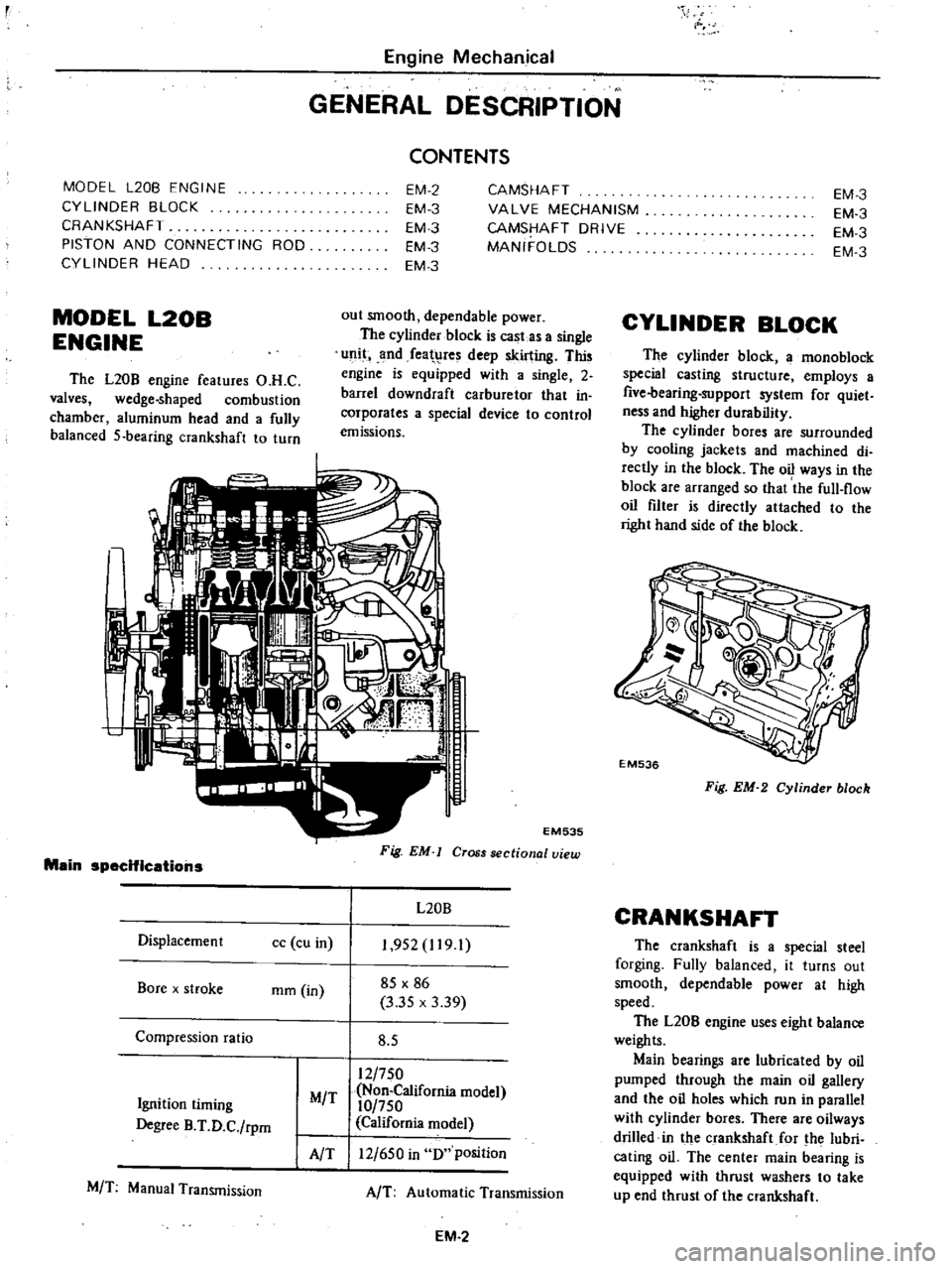
The
L20B
engine
features
O
H
C
valves
wedge
shaped
combustion
chamber
aluminum
head
and
a
fully
balanced
5
bearing
crankshaft
to
turn
Main
specifications
Oisplacemen
t
cc
cu
in
Bore
x
stroke
mm
in
Compression
ratio
Ignition
timing
Degree
B
T
O
C
rpm
MIT
AlT
MIT
Manual
Transmission
EM535
Fig
EM
Cross
sectional
view
L20B
1
952
1191
85
X
86
3
35
x
3
39
8
5
12
750
Non
California
model
10
750
California
model
12
650
in
0
position
AIT
Automatic
Transmission
EM
2
EM
3
EM
3
EM
3
EM
3
CYLINDER
BLOCK
The
cylinder
block
a
mono
block
special
casting
structure
employs
a
five
bearing
support
system
for
quiet
ness
and
higher
durability
The
cylinder
bores
are
surrounded
by
cooling
jackets
and
machined
di
rectly
in
the
block
The
oil
ways
in
the
block
are
arranged
so
that
the
full
flow
oil
filter
is
directly
attached
to
the
right
hand
side
of
the
block
EM536
Fig
EM
2
Cylinder
block
CRANKSHAFT
The
crankshaft
is
a
special
steel
forging
Fully
balanced
it
turns
out
smooth
dependable
power
at
high
speed
The
L20B
engine
uses
eight
balance
weights
Main
bearings
are
lubricated
by
oil
pumped
through
the
main
oil
gallery
and
the
oil
holes
which
run
in
parallel
with
cylinder
bores
There
are
oilways
drilled
in
the
crankshaft
for
the
lubri
cating
oil
The
center
main
bearing
is
equipped
with
thrust
washers
to
take
up
end
thrust
of
the
crankshaft
Page 48 of 537
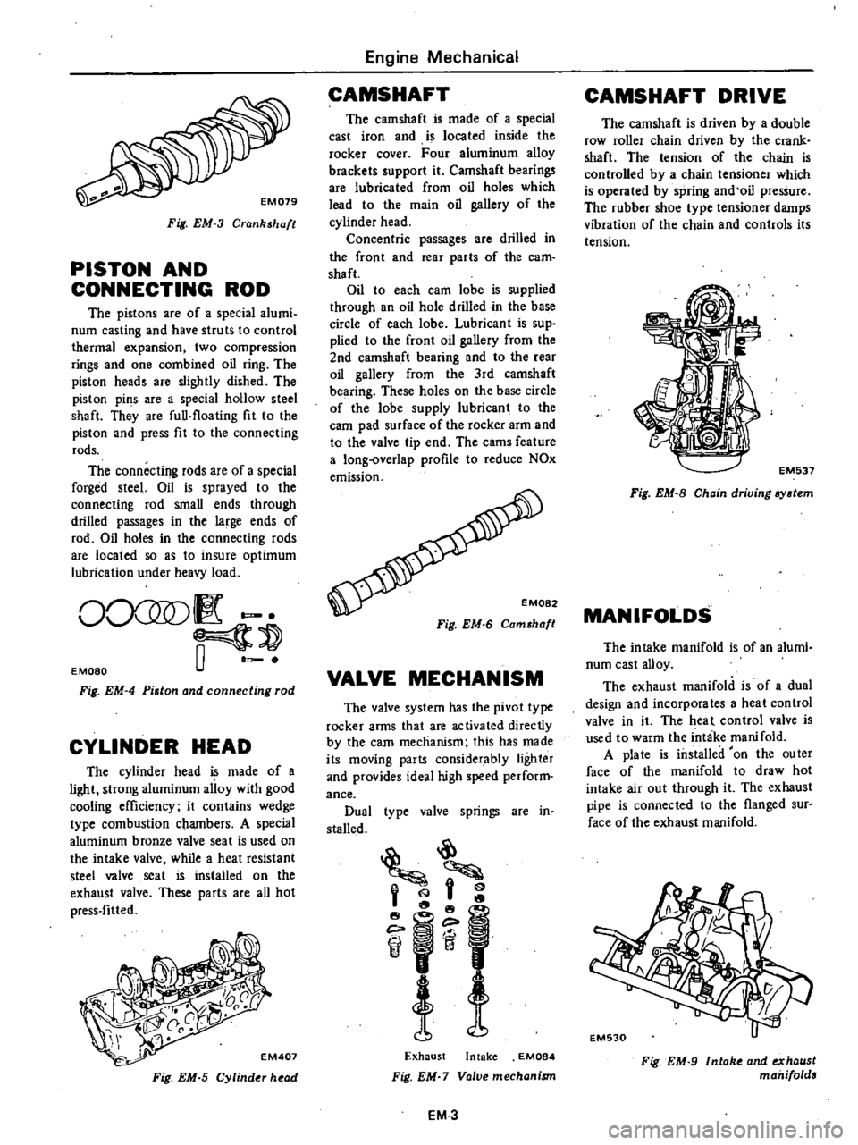
Fig
EM
3
Crankshafl
PISTON
AND
CONNECTING
ROD
The
pistons
are
of
a
special
alumi
num
casting
and
have
struts
to
control
thermal
expansion
two
compression
rings
and
one
combined
oil
ring
The
piston
heads
are
slightly
dished
The
piston
pil1S
are
a
special
hollow
steel
shaft
They
are
full
floating
fit
to
the
piston
and
press
fit
to
the
connecting
rods
The
connecting
rods
are
of
a
special
forged
steel
Oil
is
sprayed
to
the
connecting
rod
small
ends
through
drilled
passages
in
the
large
ends
of
rod
Oil
holes
in
the
connecting
rods
are
located
so
as
to
insure
optimum
lubrication
under
heavy
load
0
50
1
o
E
Moao
Fig
EM
4
Piston
and
connecting
rod
CYLINDER
HEAD
The
cylinder
head
is
made
of
a
light
strong
aluminum
alloy
with
good
cooling
efficiency
it
contains
wedge
type
combustion
chambers
A
special
aluminum
bronze
valve
seat
is
used
on
the
intake
valve
while
a
heat
resistant
steel
valve
seat
is
installed
on
the
exhaust
valve
These
parts
are
all
hot
press
fitted
EM407
Fig
EM
S
Cylinder
head
Engine
Mechanical
CAMSHAFT
The
camshaft
is
made
of
a
special
cast
iron
and
is
loca
ted
inside
the
rocker
cover
Four
aluminum
alloy
brackets
support
it
Camshaft
bearings
are
lubricated
from
oil
holes
which
lead
to
the
main
oil
gallery
of
the
cylinder
head
Concentric
passages
are
drilled
in
the
front
and
rear
parts
of
the
earn
shaft
Oil
to
each
earn
lobe
is
supplied
through
an
oil
hole
drilled
in
the
base
circle
of
each
lobe
Lubricant
is
sup
plied
to
the
front
oil
gallery
from
the
2nd
camshaft
bearing
and
to
the
rear
oil
gallery
from
the
3rd
camshaft
bearing
These
holes
on
the
base
circle
of
the
lobe
supply
lubricant
to
the
earn
pad
surface
of
the
rocker
arm
and
to
the
valve
tip
end
The
cams
feature
a
long
overlap
profile
to
reduce
NOx
emission
Fig
EM
6
Camshafl
VALVE
MECHANISM
The
valve
system
has
the
pivot
type
rocker
arms
that
are
activated
directly
by
the
earn
mechanism
this
has
made
its
moving
parts
considerably
lighter
and
provides
ideal
high
speed
perform
ance
Dual
type
valve
springs
are
in
stalled
h
@l
if
Exhaust
Intake
EM084
Fig
EM
7
Valve
mechanism
EM
3
CAMSHAFT
DRIVE
The
camshaft
is
driven
by
a
double
row
roller
chain
driven
by
the
crank
shaft
The
tension
of
the
chain
is
controlled
by
a
chain
tcosioner
which
is
operated
by
spring
and
oil
pressure
The
rubber
shoe
type
tensioner
damps
vibration
of
the
chain
and
controls
its
tension
EM537
Fig
EM
8
Chain
driving
aystem
MANIFOLDS
The
intake
manifold
is
of
an
alumi
num
cast
alloy
The
exhaust
manifold
is
of
a
dual
design
and
incorporates
a
heat
control
valve
in
it
The
heal
control
valve
is
used
to
warm
the
intake
manifold
A
plate
is
installed
on
the
outer
face
of
the
manifold
to
draw
hot
intake
air
out
through
it
The
exhaust
pipe
is
connected
to
the
flanged
sur
face
of
the
exhaust
manifold
Fig
EM
9
Intak
and
exhaust
manifolds
Page 51 of 537
r
28
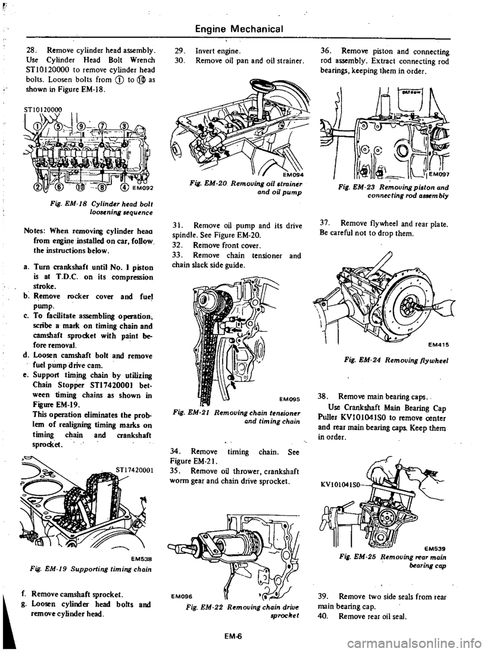
Remove
cylinder
head
assembly
Use
Cylinder
Head
Bolt
Wrench
STl0120000
to
remove
cylinder
head
bolts
Loosen
bolts
from
CD
to
@
as
shown
in
Figure
EM
18
Fig
EM
IS
Cylinder
head
bolt
loosening
equence
Notes
When
removing
cylinder
heao
from
engiJJe
installed
on
car
follow
the
instructions
below
a
Turn
crankshaft
until
No
I
pilton
is
at
T
D
C
on
its
compression
stroke
b
Remove
rocker
Cover
and
fuel
pump
c
To
facilitate
assembling
o
tion
scribe
8
mark
on
timing
c
8in
and
camshaft
sprocket
with
paint
be
fore
removal
d
Loosen
camshaft
bolt
and
remove
fuel
pump
drive
earn
e
Support
timing
chain
by
utilizing
Chain
Stopper
STl7420001
bet
ween
timiilg
chains
as
shown
in
Figure
EM
19
This
0
peration
eliminates
the
prob
lem
of
realigning
timing
marks
on
timing
chain
and
crankshaft
sprocket
EM538
Fig
EM
19
Supporting
timing
chain
f
Remove
camshaft
sprocket
g
Loosen
cylinder
head
bolts
and
remove
cylinder
head
Engine
Mechanical
29
Invert
engine
30
Remove
oil
pan
and
oil
strainer
EM094
Fig
EM
20
Removing
oil
traintir
and
oil
pump
31
Remove
oil
pump
and
its
drive
spindle
See
Figure
EM
20
32
Remove
front
cover
33
Remove
chain
tensioner
and
chain
slack
side
guide
EM095
Fig
EM
21
Removing
chain
ten
ioner
and
tim
ing
chain
34
Remove
timing
chain
See
Figure
EM
2l
35
Remove
oil
thrower
crankshaft
wonn
gear
and
chain
drive
sprocket
Fig
EM
22
Removing
chain
drive
Proc
et
EM
6
36
Remove
piston
and
connecting
rod
a
mbly
Extract
connecting
rod
bearings
keeping
them
in
order
I
Fig
EM
23
Removing
pilton
and
connecting
rod
aat
m
b
y
37
Remove
flywheel
and
rear
plate
Be
careful
not
to
drop
them
EM415
Fig
EM
24
Removing
flywheel
38
Remove
main
bearing
caps
Use
Crankshaft
Main
Bearing
Cap
Puller
KVIOI04ISO
to
remove
center
and
rear
main
bearing
caps
Keep
them
in
order
KVIOI04IS0
EM539
Fig
EM
25
Removing
rear
main
bearing
cap
39
Remove
two
side
seals
from
rear
main
bearing
ca
p
40
Remove
rear
oil
seal
Page 72 of 537
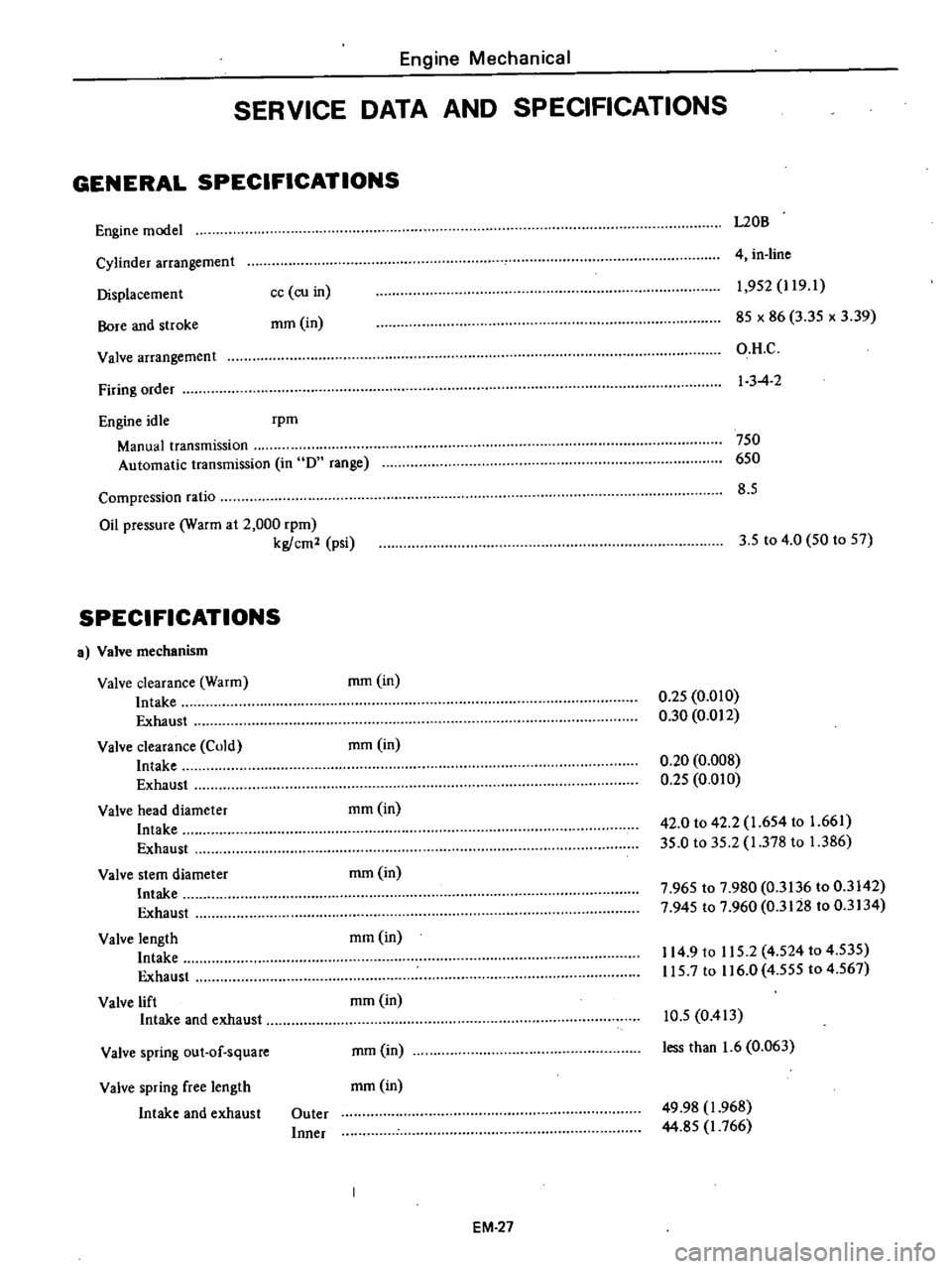
Engine
Mechanical
SERVICE
DATA
AND
SPECIFICATIONS
GENERAL
SPECIFICATIONS
Engine
model
L20B
Cylinder
arrangement
Displacemen
t
Bore
and
stroke
4
in
line
cc
co
in
mm
in
1
952
J
19
1
85
x
86
3
35
x
3
39
O
H
C
I
3
4
2
Valve
arrangement
Firing
order
Engine
idle
rpm
Manual
transmission
Automatic
transmission
in
D
range
750
650
8
5
Compression
ratio
Oil
pressure
Warm
at
2
000
rpm
kg
cm2
psi
3
5
to
4
0
50
to
57
SPECIFICATIONS
a
Valve
mechanism
Valve
clearance
Warm
Intake
Exhaust
Valve
clearance
Cold
Intake
Exhaust
Valve
head
diameter
Intake
Exhaust
Valve
stem
diameter
Intake
Exhaust
Valve
length
Intake
Exhaust
Valve
lift
Intake
and
exhaust
mm
in
0
25
0
010
0
30
0
012
mmOn
0
20
0
008
0
25
0
010
mm
in
42
0
to
42
2
1
654
to
1
661
35
0
to
35
2
1
378
to
1
386
mm
in
7
965
to
7
980
0
3136
to
0
3142
7
945
to
7
960
0
3128
to
0
3134
mmOn
114
9
to
115
2
4
524
to
4
535
115
7
to
116
0
4
555
to
4
567
mmOn
Valve
spring
out
of
square
mm
in
10
5
0
413
less
than
1
6
0
063
Valve
spring
free
length
mm
in
Intake
and
exhaust
Outer
Inner
49
98
1
968
44
85
J
766
EM
27
Page 357 of 537

SHOCK
ABSORBER
REMOVAL
AND
INSTAUATION
1
Raise
vehicle
on
a
hoist
or
stands
2
Remove
wheel
3
Hold
the
upper
stem
of
shock
absorber
and
remove
outs
washer
and
rubber
bushing
4
Remove
bolt
from
the
lower
end
of
shock
absorber
FA232
Fig
FA
13
Shock
absorber
S
Retain
lower
rubber
bushing
in
position
install
the
lower
end
of
shock
absorber
to
the
bracket
of
lower
link
and
torque
the
bolt
to
3
1
to
4
1
kg
m
23
to
30
ft
lb
Note
Insert
the
bolt
from
the
front
side
of
vehicle
6
Install
the
upper
end
of
shock
absorber
to
body
bracket
and
tighten
lock
n
Jt
to
the
specifjcations
Tightening
torque
1
6
to
2
2
kg
m
121016
ft
lb
INSPECTION
I
Check
shock
absorber
for
visible
defects
and
oil
leaks
Place
shock
absorber
vertically
in
a
vise
and
hand
stroke
shock
absorber
as
outlined
be
low
Extend
and
compress
shock
ab
sorber
as
faI
as
possible
travelling
as
long
as
possible
If
smooth
hydraulic
resistance
is
not
present
in
bqth
Iirection
replace
absorber
2
Replace
rubber
bushing
if
crack
or
deterioration
is
detected
Front
Axle
Front
Suspension
Specifications
for
shock
absorber
Model
Item
Piston
stroke
mm
in
Damping
force
kg
lb
0
3
m
sec
0
98
ft
sec
j
Rebound
Compression
STABILIZER
REMOVAL
AND
INSTAUATION
I
Raise
vehicle
on
a
hoist
or
stands
2
Remove
wheel
3
Loosen
secUring
nut
at
the
lower
link
side
of
stabilizer
4
Remove
bolt
securing
stabilizer
mounting
bracket
to
chassis
frame
Install
stabilizer
in
the
reverse
se
quence
to
removal
noting
the
follow
ing
instructions
S
Attach
stabilizer
mounting
brack
et
to
chassis
frame
tightening
bolt
to
1
6
to
2
2
kg
m
12
to
16
ft
lb
torque
6
Install
stabilizer
lower
link
side
to
connecting
rod
and
tighten
nut
to
the
specifications
as
shown
in
Figure
FA
14
Then
torque
lock
nut
toJ
6
to
2
2
kg
m
12
to
16
ft
lb
F
A233
Fig
FA
14
Stabilizer
detail
INSPECTION
Check
stabilizer
for
deformation
FA
S
All
models
110
4
3
76
168
38
84
and
rubber
bushings
for
crack
wear
and
deterioration
Replace
if
ne
cessary
TENSION
POD
REMOVAL
AND
INSTALLATION
I
Raise
vehicle
on
a
hoist
or
stands
2
Remove
wheel
3
Remove
nuts
CD
from
both
ends
of
tension
rod
4
Remove
bracket
bolt
@
from
the
front
end
of
tension
rod
and
remove
tension
rod
with
bracket
CD
@
f
A234
Fig
FA
15
Ten
ion
rod
Install
tension
rod
in
reverse
00
qunce
to
removal
noting
the
following
instructions
Page 526 of 537

INSPECTION
Check
for
gas
leakage
as
follows
I
Plug
high
and
low
pressure
joints
on
compressor
with
blind
caps
2
Connect
charging
hoses
in
lines
between
manifold
gauge
and
high
and
low
pressure
service
valves
Connect
refrigerant
can
to
middle
hose
of
manifold
gauge
3
Open
valve
of
can
tap
and
charge
refrigerant
Loosen
oil
filler
plug
at
side
of
compressor
to
purge
air
out
of
compressor
4
Turn
shaft
5
or
6
turns
Then
confirm
that
pressure
does
not
decrease
on
low
pressure
gauge
If
gauge
indicates
a
pressure
decrease
there
is
a
leak
Conduct
a
leak
test
Under
such
a
condition
remove
and
then
install
parts
again
CYLINDER
HEAD
AND
VALVES
Insufficient
refrigerant
compression
is
likely
to
be
caused
by
damaged
head
gasket
or
damaged
valves
Prior
to
servicing
the
head
and
valve
plate
both
service
valves
should
be
opened
to
free
any
gas
pressure
which
may
be
in
the
compressor
REMOVAL
I
Remove
the
bolts
from
flanged
type
service
valves
using
Torx
Driver
Bit
Note
The
direction
of
flanged
type
service
valves
should
be
noted
for
reinstallation
AC812
Fig
AC
66
Removing
service
valves
2
Remove
the
remaining
bolts
in
the
head
Air
Conditioning
AC813
Fig
A
C
6
7
Removing
cylinder
head
bolts
3
Remove
valve
plate
and
head
from
cylinder
by
prying
or
tapping
under
the
ears
which
extend
from
valve
plate
If
head
and
valve
plate
adhere
hold
head
and
tap
valve
plate
ears
away
from
head
with
a
soft
hammer
Note
Do
not
hit
or
tap
head
to
separate
head
and
valve
plate
be
3use
damage
to
head
may
result
Fig
AC
68
Removing
valve
plate
and
head
4
When
removing
the
gaskets
use
a
sharp
edged
knife
Notes
a
In
removing
head
gasket
be
very
careful
not
to
damage
machined
sealing
surface
b
Do
not
reuse
gaskets
AC815
Fig
A
C
69
Removing
gasket
AC37
INSTALLATION
Valves
and
valve
plates
are
furnish
ed
only
as
a
complete
assembly
I
Apply
a
thin
film
of
clean
refrig
eration
oil
on
area
of
crankcase
to
be
covered
by
cylinder
gasket
2
Place
cylinder
gasket
in
position
on
cylinder
so
dowel
pins
in
crankcase
go
through
dowel
pin
holes
in
cylinder
gasket
3
Apply
a
thin
film
of
clean
refrig
eration
oil
to
top
and
bottom
valve
plate
areas
to
be
covered
by
gaskets
AC816
Fig
A
C
70
Applying
clean
refrigeration
oil
4
Place
valve
plate
in
position
on
cylinder
gasket
so
discharge
valve
as
semblies
i
e
smaller
diameter
assem
blies
with
restrainer
over
valve
reed
are
facing
up
and
locating
dowel
pins
go
through
dowel
pin
holes
in
valve
plate
Fig
A
C
71
Placing
valve
plate