four wheel drive DATSUN PICK-UP 1977 Service Manual
[x] Cancel search | Manufacturer: DATSUN, Model Year: 1977, Model line: PICK-UP, Model: DATSUN PICK-UP 1977Pages: 537, PDF Size: 35.48 MB
Page 160 of 537

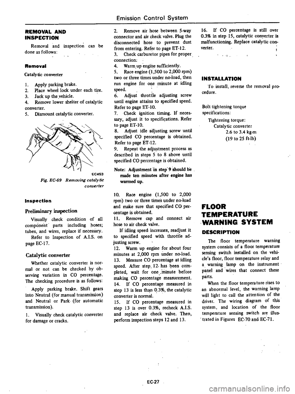
REMOVAL
AND
INSPECTION
Removal
and
inspection
can
be
done
as
follows
Removal
Catalytic
converter
1
Apply
parking
brake
2
Place
wheel
lock
under
each
tire
3
Jack
up
the
vehicle
4
Remove
lower
shelter
of
catalytic
converter
5
Dismount
catalytic
converter
EC453
Fig
EC
69
Removing
catalytic
conuerter
Inspection
Preliminary
inspection
Visually
check
condition
of
all
component
parts
including
ho
s
tubes
and
wires
replace
if
necessary
Refer
to
Inspection
of
A
I
S
on
page
EC
17
Catalytic
converter
Whether
catalytic
converter
is
nor
mal
or
not
can
be
checked
by
ob
serving
variation
in
CO
percentage
The
checking
procedure
is
as
follows
Apply
parking
brake
Shift
gears
into
Neutral
for
manual
transmission
and
Neutral
or
Park
for
automatic
transmission
1
Visually
check
catalytic
converter
for
damage
or
cracks
Emission
Control
System
2
Remove
air
hose
between
5
way
connector
and
air
check
valve
Plug
the
disconnected
hose
to
prevent
dust
from
entering
Refer
to
page
ET
12
3
Check
carburetor
pipes
for
proper
connection
4
Warm
up
engine
sufficiently
5
Race
engine
1
500
to
2
000
rpm
two
or
three
times
under
no
load
then
run
engine
for
o
e
minute
at
idling
speed
6
Adjust
throttle
adjusting
screw
until
engine
attains
to
specified
speed
Refer
to
page
ET
10
7
Check
ignition
timing
If
neces
sary
adjust
it
to
specifkations
Refer
to
page
ET
10
B
Adjust
idle
adjusting
screw
until
specified
CO
percentage
is
obtained
Refer
to
page
ET
12
9
Repeat
the
adju
stment
process
as
described
in
steps
5
to
8
above
until
specified
CO
percentage
is
obtained
Note
Adjustment
in
step
9
should
be
made
ten
minutes
after
engine
has
wanned
up
10
Race
engine
1
500
to
2
000
rpm
two
or
three
times
under
no
load
and
make
sure
that
specified
CO
per
centage
is
obtained
11
Remove
cap
and
connect
air
hose
to
air
check
valve
If
idling
speed
increases
readjust
it
to
specified
speed
with
throttle
ad
justing
screw
12
WaRn
up
engine
for
about
four
minutes
at
2
000
rpm
under
no
load
13
Measure
CO
percentage
at
idling
speed
After
step
12
has
been
coin
pleted
wait
for
one
minute
before
making
CO
percentage
measurement
14
If
CO
percentage
measured
in
step
13
is
less
than
0
3
the
catalytic
converter
is
normal
15
If
CO
percentage
measured
in
step
13
is
over
0
3
recheck
A
I
S
and
replace
air
check
valve
Then
perform
inspection
steps
12
and
13
EC
27
16
If
CO
percentage
is
still
over
0
3
in
step
15
catalytic
conyerter
is
malfunctioning
Replace
catalytic
con
verter
INSTALLATION
To
install
reverse
the
removal
pro
cedure
Bolt
lightening
torque
specifications
Tightening
torque
Catalytic
converter
2
6
to
3
4
kg
m
19
to
25
ft
Ib
FLOOR
TEMPERATURE
WARNING
SYSTEM
DESCRIPTION
The
floor
temperature
warning
system
consists
of
a
floor
temperature
sensing
switch
installed
on
the
vehi
cle
s
floor
floor
temperature
relay
and
a
warning
lamp
on
the
instrument
panel
and
wires
that
connect
these
parts
When
the
floor
tempera
ture
rises
to
an
abnormal
level
the
warning
lamp
will
light
to
call
the
attention
of
the
driver
The
wiring
diagram
of
this
system
and
location
of
the
floor
temperature
sensing
switch
are
ilIus
trated
in
Figures
EC
70
and
EC
71
Page 377 of 537

The
620
series
vehicles
are
equip
ped
with
hydraulic
brakes
on
the
four
wheels
and
mechanical
hand
brakes
on
the
rear
wheels
The
front
brake
is
the
uni
servo
type
and
the
rear
the
duo
servo
with
the
built
in
hand
BRAKE
PEDAL
FRONT
BRAKE
REAR
BRAKE
BRAKE
PEDAL
Qi
f
l
II
t
Unit
mm
in
I
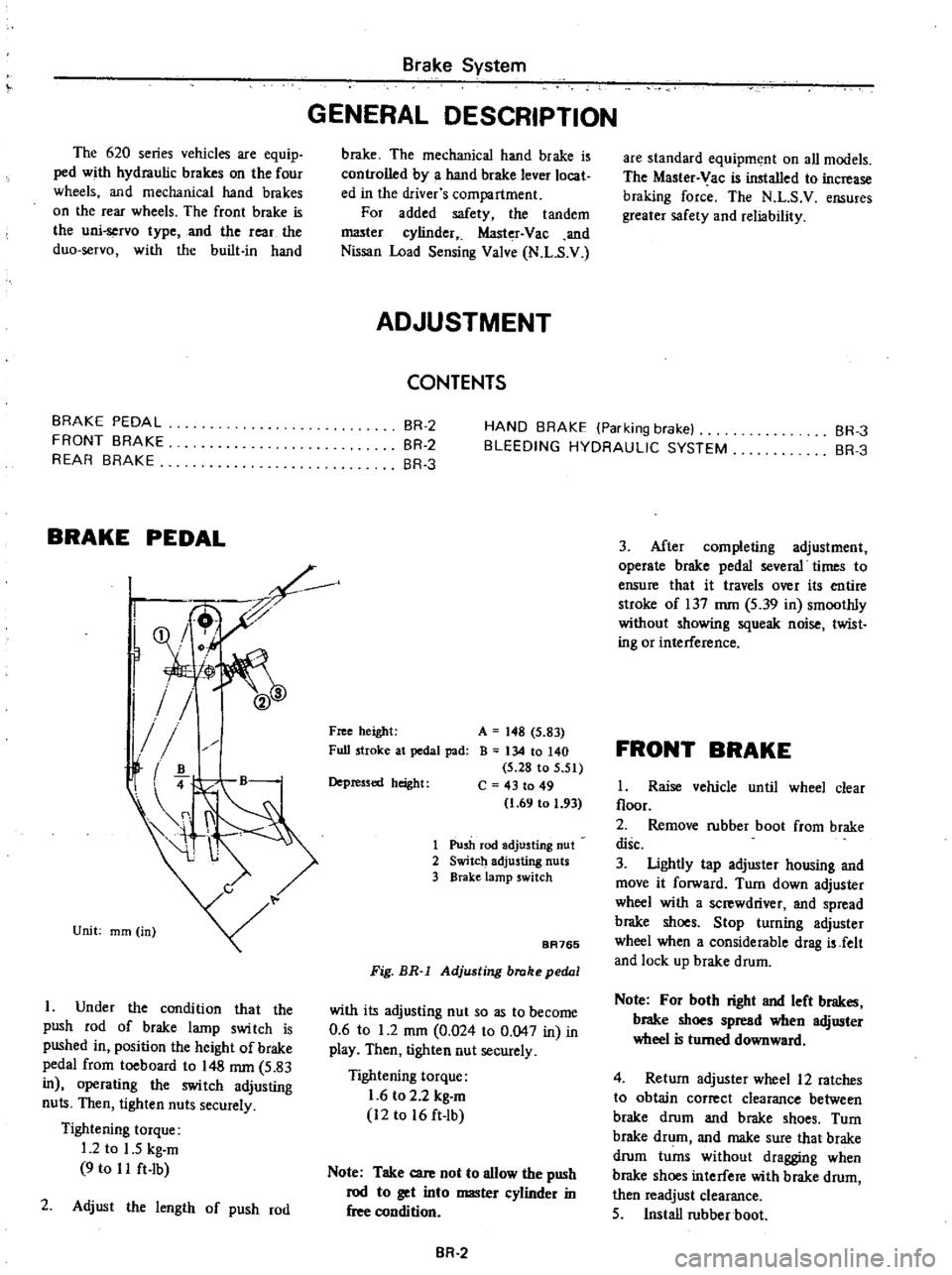
Under
the
condition
that
the
push
rod
of
brake
lamp
swi
tch
is
pushed
in
position
the
height
of
brake
pedal
from
toeboard
to
148
mm
5
83
in
operating
the
switch
adjusting
nuts
Then
tighten
nuts
securely
Tightening
torque
1
2
to
1
5
kg
m
9
to
I
I
ft
Ib
2
Adjust
the
length
of
push
rod
Brake
System
GENERAL
DESCRIPTION
brake
The
mechanical
hand
brake
is
controlled
by
a
hand
brake
lever
locat
ed
in
the
driver
s
compartment
For
added
safety
the
tandem
I
1lI3ter
cylinder
Master
Vac
and
Nissan
Load
Sensing
Valve
N
L
S
V
ADJUSTMENT
CONTENTS
are
standard
equipment
on
all
models
The
Master
Vac
is
installed
to
increase
braking
force
The
N
L
S
V
ensures
greater
safety
and
reliability
BR
2
BR
2
BR
3
HAND
BRAKE
Parking
brake
BLEEDING
HYDRAULIC
SYSTEM
BR
3
BR
3
Free
height
Full
stroke
at
pedal
pad
A
148
5
83
B
134
10
140
5
28
to
5
51
C
43
to
49
1
69
to
1
93
Depressed
height
1
Push
rod
adjusting
nut
2
Switch
adjusting
nuts
3
BraKe
lamp
switch
BA765
Fig
BR
l
Adjusting
brake
pedal
with
its
adjusting
nut
so
as
to
become
0
6
to
1
2
mOl
0
024
to
0
047
in
in
play
Then
tigh1en
nut
securely
Tightening
torque
1
6
to
2
2
kg
m
12
to
16
ft
lb
Note
Take
care
not
to
allow
the
push
rod
to
get
into
master
cylinder
in
free
condition
BR
2
3
After
completing
adjustment
operate
brake
pedal
several
times
to
ensure
that
it
travels
over
its
entire
stroke
of
137
mm
5
39
in
smoothly
without
showing
squeak
noise
twist
ing
or
interference
FRONT
BRAKE
1
Raise
vehicle
until
wheel
clear
floor
2
Remove
rubber
boot
from
brake
disc
3
Ughtly
tap
adjuster
housing
and
move
it
forward
Turn
down
adjuster
wheel
with
a
screwdriver
and
spread
brake
shoes
Stop
turning
adjuster
wheel
when
a
considerable
drag
is
Jelt
and
lock
up
brake
drum
Note
For
both
right
and
left
brakes
brake
shoes
spread
when
adjuster
wheel
is
turned
downward
4
Return
adjuster
wheel
12
ratches
to
obtain
correct
clearance
between
brake
drum
and
brake
shoes
Turn
brake
drum
and
make
sure
that
brake
drum
turns
without
dragging
when
brake
shoes
interfere
with
brake
drum
then
readjust
clearance
5
Install
rubber
boot