roof DATSUN PICK-UP 1977 Service Manual
[x] Cancel search | Manufacturer: DATSUN, Model Year: 1977, Model line: PICK-UP, Model: DATSUN PICK-UP 1977Pages: 537, PDF Size: 35.48 MB
Page 300 of 537

Automatic
Transmission
MAJOR
REPAIR
OPERATION
SERVICE
NOTICE
FOR
DISASSEMBLY
AND
ASSEMBLY
TORQUE
CONVERTER
INSPECTION
TRANSMISSION
DISASSEMBL
Y
INSPECTION
ASSEMBL
Y
SERVICE
NOTICE
FOR
DISASSEMBLY
AND
ASSEMBLY
I
It
is
advisable
that
repair
opera
tions
be
carried
out
in
a
dust
proof
room
2
Due
to
the
differences
of
the
engine
capacities
the
specifications
of
component
parts
for
each
model
s
transmission
may
be
different
They
do
however
have
common
adjust
ment
and
repair
procedures
as
well
as
cleaning
and
inspection
procedures
outlined
hereinafter
3
During
repair
operations
refer
to
Service
Data
and
Specifications
see
tion
for
the
correct
parts
for
each
model
4
Before
removing
any
of
subas
semblies
thoroughly
clean
the
outside
of
the
transmission
to
prevent
dirt
from
entering
the
mechanical
parts
5
Do
not
use
a
waste
rag
Use
a
nylon
or
paper
cloth
6
After
disassembling
wash
all
dis
assembled
parts
and
examine
them
to
see
if
there
are
any
worn
damaged
or
defective
parts
and
how
they
are
affected
Refer
to
Service
Data
for
the
extent
of
damage
that
justifies
replacement
7
As
a
rule
packings
seals
and
similar
parts
once
disassembled
should
be
replaced
with
new
ones
TORQUE
CONVERTER
The
torque
converter
is
a
welded
construction
and
can
not
be
disas
sembled
CONTENTS
AT
36
AT
36
AT
36
AT
36
AT
36
AT
38
AT
38
COMPONENT
PARTS
FRONT
CLUTCH
REAR
CLUTCH
LOW
REVERSE
BRAKE
SERVO
PISTON
GOVERNOR
OIL
PUMP
PLANETARY
CARRIER
CONTROL
VALVE
AT
40
AT
40
AT
41
AT
42
AT
42
AT
43
AT
43
AT
44
AT
44
INSPECTION
2
Remove
bolts
securing
converter
1
Check
torque
convertf
for
any
housing
to
transmission
case
Remove
sign
of
damage
bending
oil
leak
or
torque
converter
deformation
If
necessary
replace
3
Remove
speedometer
pinion
2
Remove
rust
from
pilots
and
sleeve
bolt
Withdraw
pinion
bosses
completely
4
Remove
downshift
solenoid
and
If
torque
converter
oil
is
fouled
or
vacuum
diaphragm
Do
not
leave
dia
contaminated
due
to
burnt
clutch
phragm
rod
at
this
stage
of
disas
flush
the
torque
converter
as
follows
sembly
Rod
is
assembled
in
top
of
vacuum
diaphragm
See
Figure
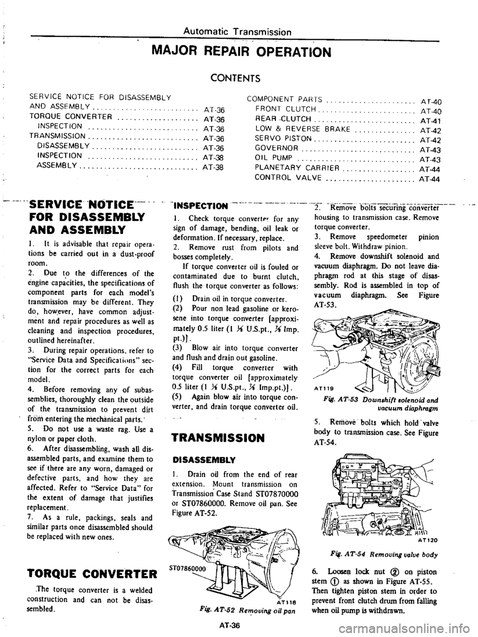
I
Drain
oil
in
torque
converter
AT
53
2
Pour
non
lead
gasoline
or
kero
sene
into
torque
converter
approxi
mately
0
5
liter
I
U
S
pt
U
Imp
pt
3
Blow
air
into
torque
converter
and
flush
and
drain
out
gasoline
4
Fill
torque
converter
with
torque
converter
oil
approximately
0
5
liter
I
V
S
pt
U
Imp
pt
5
Again
blow
air
into
torque
con
verter
and
drain
torque
converter
oil
TRANSMISSION
DISASSEMBLY
I
Drain
oil
from
the
end
of
rear
extension
Mount
transmission
on
Transmission
Case
Stand
ST07870000
or
ST07860000
Remove
oil
pan
See
Figure
AT
52
AT118
Fig
AT
52
Removing
oil
pan
AT
36
Fig
AT
53
Down
hilt
olenoid
and
vacuum
dilJphragm
5
Remove
bolts
which
hold
valve
body
to
transmission
case
See
Figure
AT
54
Fig
AT
54
Removing
valve
body
6
Loosen
lock
nut
@
on
piston
stem
D
as
shown
in
Figure
AT
55
Then
tighten
piston
stem
in
order
to
prevent
front
clutch
drum
from
falling
when
oil
pump
is
withdrawn
Page 356 of 537

Components
Rust
Discoloring
Race
and
roller
u
u
e
2
2
0
3
0
t
c
6
6
6
Fig
h
The
wheel
bearing
is
serv
iceable
if
discoloring
can
be
removed
with
solvent
or
by
polishing
f
a
Inner
race
flaking
t
d
Cracked
roller
iT
t
j
t
11
1
1
t
t
I
l
1
t
F
1ll
JJ
J
t
I
1
ollf
oe
c
g
Recess
on
foDer
Front
Axle
Front
Suspension
Cause
Temperature
increased
during
operation
lowers
when
the
bearing
stops
moisture
inside
the
bearing
is
condensed
becoming
fine
drips
and
the
grease
is
moistened
The
bearing
has
been
placed
in
a
highly
moistened
place
for
a
long
period
of
time
Intrusion
of
moisture
chemicals
etc
or
the
bearing
is
touched
with
bare
hand
and
no
rustproof
action
has
been
taken
Slight
discoloring
may
become
like
oxidized
oil
stain
due
to
grease
In
the
most
cases
this
occurs
when
preliminary
pressure
is
too
high
I
I
I
1
v
i
n
dJ
b
RoUer
flaking
c
Cracked
inner
race
c
f
J
Jt
v
l
e
Recess
on
inner
race
f
Recess
on
outer
race
h
Rust
outer
race
F
A007
Fig
FA
12
Defective
conditions
of
bearing
FA
7
Page 442 of 537

Body
Frame
INTERIOR
TRIM
AND
CENTER
CONSOLE
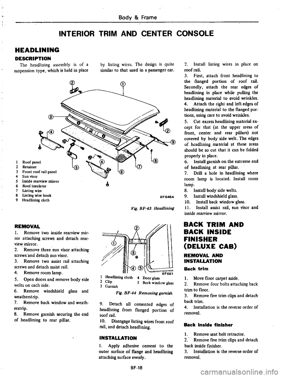
HEADLINING
DESCRIPTION
The
headlining
assembly
is
of
a
suspension
type
which
is
held
in
place
ct
I
2
3
4
5
6
7
8
9
REMOVAL
1
Remove
two
inside
rearview
mir
ror
attaching
screws
and
detach
rear
view
mirror
2
Remove
three
sun
visor
attaching
screws
and
detach
sun
visor
3
Remove
two
assist
rail
attaching
screws
and
detach
assist
rail
4
Remove
room
lamp
5
Open
doors
and
remove
body
side
welts
on
each
side
6
Remove
windshield
glass
and
weatherstrip
7
Remove
back
window
and
weath
erstrip
8
Remove
garnish
securing
the
end
of
headlining
to
rear
pillar
by
listing
wires
The
design
is
quite
similar
to
that
used
in
a
passenger
car
A
BF648A
Fig
BF
43
Headlining
CD
r
h
i
r
J
I
I
I
II
CID
BF661
1
Headlining
cloth
4
Door
glass
2
Clip
5
Back
window
glass
3
Garnish
Fig
BF
44
Removing
gami8h
9
Detach
all
cemented
edges
of
headlining
from
flanged
portion
of
roof
rail
10
Disengage
listing
wires
from
roof
rail
and
detach
headlining
INSTALLATION
I
Apply
adhesive
cement
to
the
outer
surface
of
flange
and
headlining
attaching
surface
evenly
8F
18
2
Install
listing
wires
in
place
on
roof
rail
3
First
attach
front
headlining
to
the
flanged
portion
of
roof
rail
Secondly
attach
the
rear
edges
of
headlining
in
place
while
pulling
the
headlining
material
to
avoid
wrinkles
4
Attach
the
right
and
left
edges
of
headlining
material
to
the
flanged
por
tions
using
care
to
avoid
wrinkles
5
Cut
excess
headlining
material
ex
cept
for
that
at
the
upper
areas
of
front
center
and
rear
pillars
not
covered
by
body
side
welt
The
edges
of
headlining
ma
terial
at
these
areas
should
be
so
cut
that
it
can
be
folded
properly
in
place
6
Install
garnish
on
the
extreme
end
of
headlining
at
rear
pillar
7
Drill
a
hole
in
headlining
where
room
lamp
is
located
Install
room
lamp
8
Install
body
side
welts
9
Install
windshield
glass
10
Install
back
window
glass
11
Install
assist
rail
sun
visor
and
inside
rearview
mirror
BACK
TRIM
AND
BACK
INSIDE
FINISHER
DELUXE
CAB
REMOVAL
AND
INSTALLATION
Back
trim
I
Move
floor
carpet
aside
2
Remove
four
bolts
attaching
back
trim
to
floor
3
Remove
five
trim
clips
and
detach
back
trim
4
Installation
is
the
reverse
order
of
removal
Back
Inside
finisher
I
Remove
seat
belt
retractor
2
Remove
five
trim
clips
and
detach
back
inside
fmisher
3
Installation
is
the
reverse
order
of
removal
Page 453 of 537

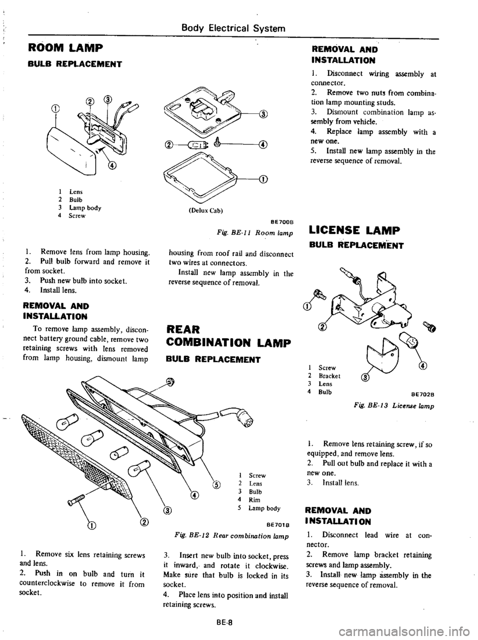
ROOM
LAMP
BULB
REPLACEMENT
1
Lens
2
Bulb
3
Lamp
body
4
Screw
Remove
lens
from
lamp
housing
2
Pull
bulb
forward
and
remove
it
from
socket
3
Push
new
bulb
into
socket
4
Install
lens
REMOVAL
AND
INSTALLATION
To
remove
lamp
assembly
discon
nect
battery
ground
cable
remove
two
retaining
screws
with
lens
removed
from
lamp
housing
dismount
lamp
1
Remove
six
lens
retaining
screws
and
lens
2
Push
in
on
bulb
and
turn
it
counterclockwise
to
remove
it
from
socket
Body
Electrical
System
J
CD
O
lux
Cab
8E700B
Fig
HE
ll
Room
lamp
housing
from
roof
rail
and
disconnect
two
wires
at
connectors
Install
new
lamp
assembly
in
the
reverse
sequence
of
removal
REAR
COMBINATION
LAMP
BULB
REPLACEMENT
1
Screw
2
Lens
3
Bulb
4
Rim
5
Lamp
body
@
BE70tB
Fig
BE
12
Rear
combination
lamp
3
Insert
new
bulb
into
socket
press
it
inward
and
rotate
it
clockwise
Make
sure
that
bulb
is
locked
in
its
socket
4
Place
lens
into
position
and
install
retaining
screws
8E
8
REMOVAL
AND
INSTALLATION
I
Disconnect
wiring
assembly
at
cormector
2
Remove
two
nuts
from
combina
tion
lamp
mounting
studs
3
Dismount
combination
lamp
as
sembly
from
vehicle
4
Replace
lamp
assembly
with
a
new
one
5
Install
new
lamp
assembly
in
the
reverse
sequence
of
removal
LICENSE
LAMP
BULB
REPLACEMENT
1
Screw
2
Bracket
3
Lens
4
Bulb
i
J
BE702B
Fig
HE
13
License
Iomp
1
Remove
lens
retaining
screw
if
so
equipped
and
remove
lens
2
Pull
out
bulb
and
replace
it
with
a
new
one
3
Install
lens
REMOVAL
AND
I
NSTALlATI
ON
1
Disconnect
lead
wire
at
con
nector
2
Remove
lamp
bracket
retaining
screws
and
lamp
assembly
3
Install
new
lamp
assembly
in
the
reverse
sequence
of
removal