fuel consumption DATSUN PICK-UP 1977 Service Manual
[x] Cancel search | Manufacturer: DATSUN, Model Year: 1977, Model line: PICK-UP, Model: DATSUN PICK-UP 1977Pages: 537, PDF Size: 35.48 MB
Page 21 of 537
Yellow
line
Spark
delay
valve
to
distributor
Spark
delay
valve
to
vacuum
tube
Distributor
to
vacuum
tube
Vacuum
tube
to
carburetor
Vacuum
tube
to
canister
Green
line
Anti
backfire
valve
to
intake
mani
fold
Air
control
valve
to
emergency
air
relief
valve
Intake
manifold
to
vacuum
hose
connector
Intake
manifold
to
canister
CHECKING
ENGINE
COMPRESSION
COMPRESSION
PRESSURE
TEST
I
Warm
up
engine
sufficiently
2
Disconnect
all
spark
plugs
3
Disconnect
anti
dieseling
solenoid
valve
connector
4
Properly
attach
a
compression
tester
to
spark
plug
hole
in
cylinder
being
tested
Engine
Tune
up
I
ET010
Different
compression
in
two
or
more
cylinders
usually
indicates
an
improperly
seated
valve
or
broken
piston
ring
9
Low
compression
in
cylinders
can
result
from
worn
piston
rings
This
condition
may
usually
be
accompanied
by
excessive
fuel
consumption
TEST
RESULT
If
compression
in
one
or
more
cylinders
is
low
pour
a
small
quantity
of
engine
oil
into
cylinders
through
the
spark
plug
holes
and
retest
com
pression
I
If
adding
oil
increases
the
com
pression
pressure
the
chances
are
that
rings
are
faulty
2
If
pressure
stays
low
probable
cause
is
that
valve
is
sticking
or
seating
improperly
3
If
cylinder
compression
in
any
two
adjacent
cylinders
is
low
and
if
adding
oil
does
not
help
the
compres
sian
there
is
leakage
past
the
gasket
surface
Oil
and
water
in
combustion
cham
bers
can
result
from
leakage
IGNITION
AND
FUEL
SYSTEM
Fig
ET
10
Teding
compression
pressure
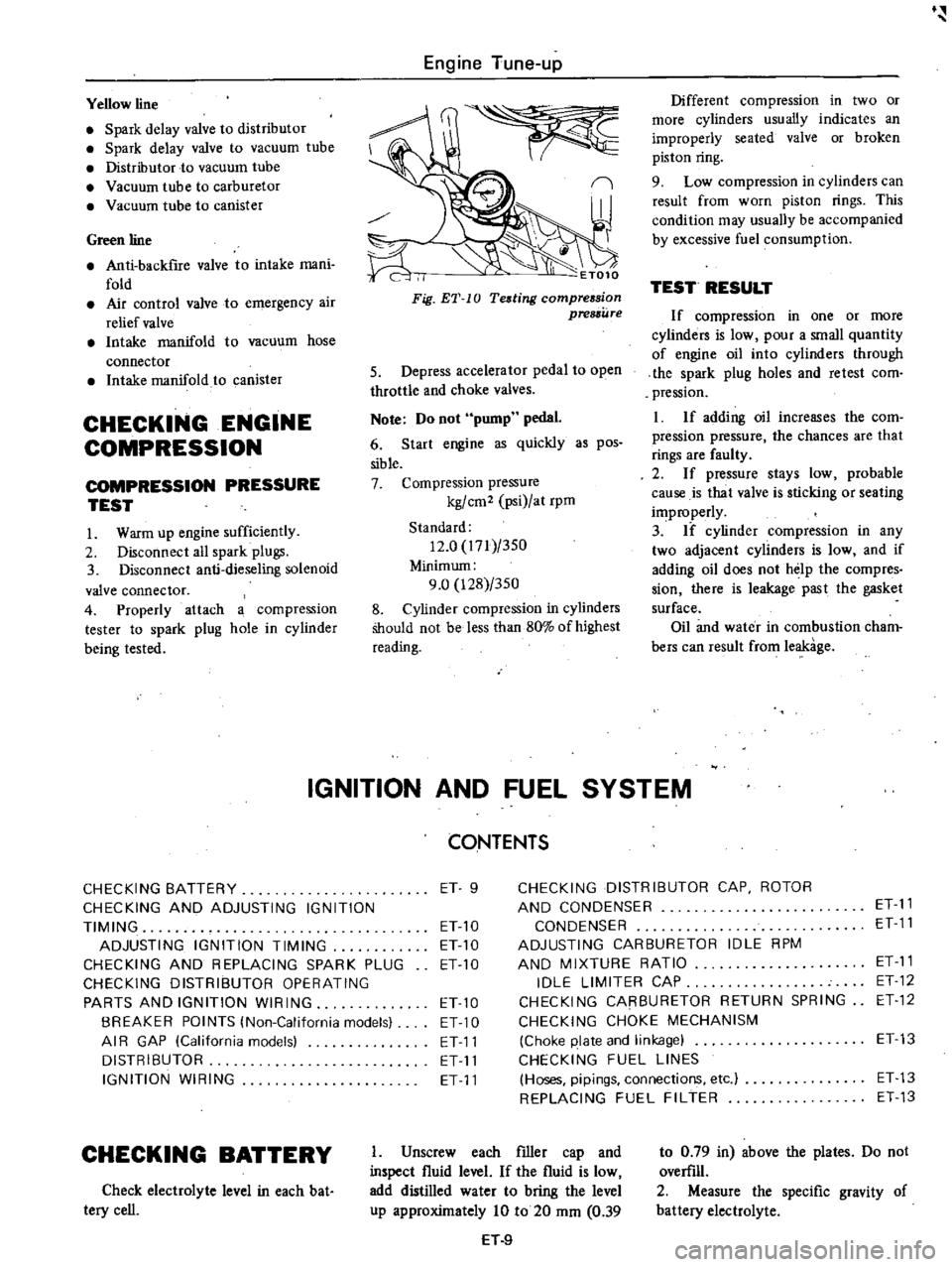
5
Depress
accelerator
pedal
to
open
throttle
and
choke
valves
Note
Do
not
pump
pedal
6
Start
engine
as
quickly
as
pos
sible
7
Compression
pressure
kg
cm2
psi
at
rpm
Standard
12
0
171
350
Minimum
9
0
128
350
8
Cylinder
compression
in
cylinders
Should
not
be
less
than
80
of
highest
reading
CONTENTS
CHECKING
BATTERY
ET
9
CHECKING
DISTRIBUTOR
CAP
ROTOR
CHECKING
AND
ADJUSTING
IGNITION
AND
CONDENSER
ET
11
TIMING
ET
10
CONDENSER
ET
11
ADJUSTING
IGNITION
TIMING
ET10
ADJUSTING
CARBURETOR
IDLE
RPM
CHECKING
AND
REPLACING
SPARK
PLUG
ETlO
AND
MIXTURE
RATIO
ET
11
CHECKING
DISTRIBUTOR
OPERATING
IDLE
LIMITER
CAP
ET
12
PARTS
AND
IGNITION
WIRING
ETlO
CHECKING
CARBURETOR
RETURN
SPRING
ET
12
BREAKER
POINTS
lNon
California
models
ET
10
CHECKING
CHOKE
MECHANISM
AI
R
GAP
lCalifornia
models
ET11
Choke
plate
and
linkage
ET13
DISTRIBUTOR
ET
11
CHECKING
FUEL
LINES
IGNITION
WIRING
ET
11
Hoses
pipings
connections
etc
ET
13
REPLACING
FUEL
FILTER
ET
13
CHECKING
BATTERY
Check
electrolyte
level
in
each
bat
tery
cell
I
Unscrew
each
filler
cap
and
inspect
fluid
level
If
the
fluid
is
low
add
distilled
water
to
bring
the
level
up
approximately
10
to
20
mm
0
39
H
9
to
0
79
in
above
the
plates
Do
not
overfill
2
Measure
the
specific
gravity
of
battery
electrolyte
Page 27 of 537
Engine
Tune
up
EC284
When
installing
this
valve
ensure
that
it
properly
oriented
This
valve
should
be
replaced
periodically
Refer
to
Maintenance
Schedule
I
To
distribut0
From
carburetor
Yl
r
EC278
l
Fig
ET
24
Operation
of
spark
delay
value
I
I
Carburetor
side
Distributor
side
rJmlL
lr
EC346
Fig
ET
25
Checking
spark
delay
value
Distributor
side
Brown
lOne
way
umbrella
valve
2
Sintered
metal
disc
Fig
ET
23
Spark
delay
valve
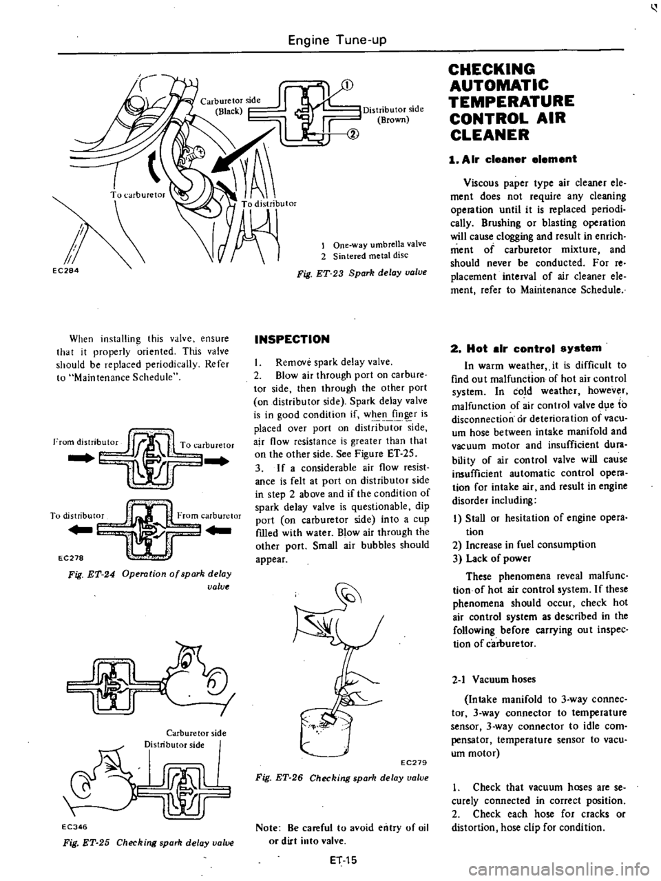
INSPECTION
I
Remove
spark
delay
valve
2
Blow
air
through
port
on
carbure
tor
side
then
through
the
other
port
on
distributor
side
Spark
delay
valve
is
in
good
condition
if
when
finger
is
placed
over
port
on
distrib
side
ajr
flow
resistance
is
greater
than
that
on
the
other
side
See
Figure
ET
25
3
If
a
considerable
air
flow
resist
ance
is
felt
at
port
on
distributor
side
in
step
2
above
and
if
the
condition
of
spark
delay
valve
is
questionable
dip
port
on
carburetor
side
into
a
cup
fIlled
with
water
Blow
air
through
the
other
port
Small
air
bubbles
should
appear
EC279
Fig
ET
26
Checking
spark
delay
ualue
Note
Be
careful
to
avoid
entry
of
oil
or
dirt
into
valve
ET
15
CHECKING
AUTOMATIC
TEMPERATURE
CONTROL
AIR
CLEANER
1
Air
cleener
element
Viscous
paper
type
air
cleaner
ele
ment
does
not
require
any
cleaning
opera
tion
until
it
is
replaced
periodi
cally
Brushing
or
blasting
operation
will
cause
clogging
and
result
in
enrich
ment
of
carburetor
mixture
and
should
never
be
conducted
For
reo
placement
interval
of
air
cleaner
ele
ment
refer
to
Maintenance
Schedule
2
Hot
elr
control
system
In
warm
wealher
it
is
difficult
to
find
ou
t
malfunction
of
hot
air
control
system
In
cold
weather
however
malfunction
of
air
control
valve
d
e
to
disconnection
or
deterioration
of
vacu
um
hose
between
intake
manifold
and
vacuum
motor
and
insufficient
dura
bili
ty
of
air
con
trol
valve
will
cause
insufficient
automatic
control
opera
tion
for
intake
air
and
result
in
engine
disorder
including
I
Stall
or
hesitation
of
engine
opera
tion
2
Increase
in
fuel
consumption
3
Lack
of
power
These
phenomena
reveal
malfunc
tionof
hot
air
control
system
If
these
phenomena
should
occur
check
hot
air
control
system
as
described
in
the
following
before
carrying
ou
t
inspec
tion
of
carburetor
2
1
Vacuum
hoses
Intake
manifold
to
3
way
connec
tor
3
way
connector
to
temperature
sensor
3
way
connector
to
idle
com
pensator
temperature
sensor
to
vacu
um
motor
1
Check
that
vacuum
hoses
are
se
curely
connected
in
correct
position
2
Check
each
hose
for
cracks
or
distortion
hose
clip
for
condition
Page 43 of 537
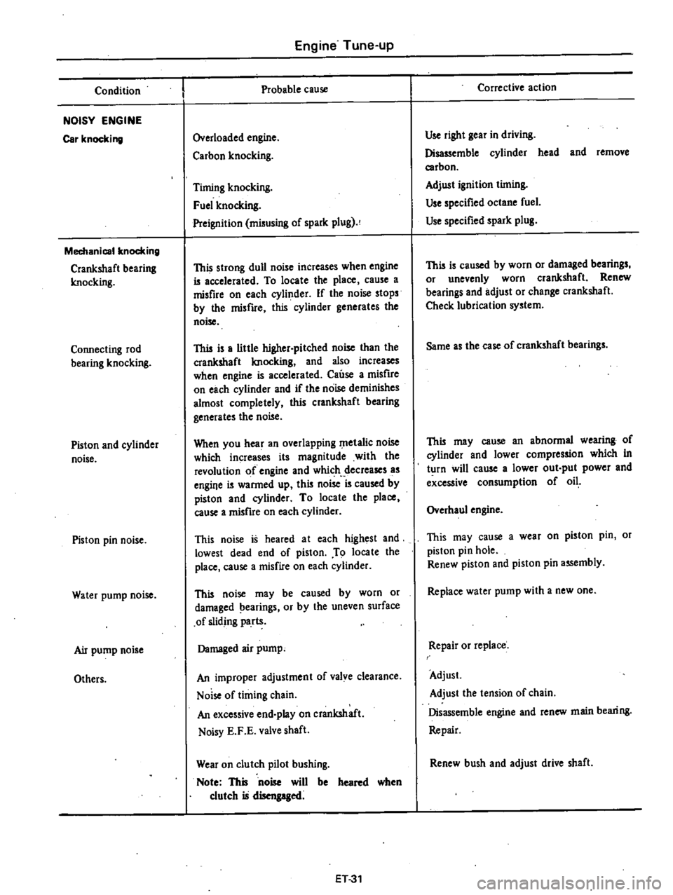
Condition
NOISY
ENGINE
Car
knocking
Mechanical
knocking
Crankshaft
bearing
Imocking
Connecting
rod
bearing
knocking
Piston
and
cylinder
noise
Piston
pin
noise
Water
pump
noise
Air
pump
noise
Others
Engine
Tune
up
Probable
cause
Overloaded
engine
Carbon
knocking
Timing
knocking
Fuel
knocking
Preignition
misusing
of
spark
plug
This
strong
dull
noise
increases
when
engine
is
accelerated
To
locate
the
place
cause
a
misfire
on
each
cylinder
If
the
noise
stops
by
the
misfire
this
cylinder
generates
the
noise
This
is
a
little
higher
pitched
noise
than
the
crankshaft
Imocking
and
also
increases
when
engine
is
accelerated
Cause
a
misfire
on
each
cylinder
and
if
the
noise
deminishes
almost
completely
this
crankshaft
bearing
generates
the
noise
When
you
hear
an
overlapping
metalic
noise
which
increases
its
magnitude
with
the
revolution
of
engine
and
which
decreases
as
engine
is
warmed
up
this
noise
is
caused
by
piston
and
cylinder
To
locate
the
place
cause
a
misfire
on
each
cylinder
This
noise
is
heared
at
each
highest
and
lowest
dead
end
of
piston
To
locate
the
place
cause
a
misfire
on
each
cylinder
This
noise
may
be
caused
by
worn
or
damaged
earings
or
by
the
uneven
surface
of
sliding
parts
Damaged
air
pump
An
improper
adjustment
of
valve
clearance
Noise
of
timing
chain
An
excessive
end
play
on
crankshaft
Noisy
E
F
E
valve
shaft
Wear
on
clutch
pilot
bushing
Note
This
noise
will
be
heared
when
clutch
is
disengaged
ET31
Corrective
action
Use
right
gear
in
driving
Disassemble
cylinder
head
and
remove
carbon
Adjust
ignition
timing
Use
specified
octane
fuel
Use
specified
spark
plug
This
is
caused
by
worn
or
damaged
bearings
or
unevenly
worn
crankshaft
Renew
bearings
and
adjust
or
change
crankshaft
Check
lubrication
system
Same
as
the
case
of
crankshaft
bearings
This
may
cause
an
abnormal
wearing
of
cylinder
and
lower
compression
which
in
turn
will
cause
a
lower
out
put
power
and
excessive
consumption
of
oil
Overhaul
engine
This
may
cause
a
wear
on
piston
pin
or
piston
pin
hole
Renew
piston
and
piston
pin
assembly
Replace
water
pump
with
a
new
one
Repair
or
replace
Adjust
Adjust
the
tension
of
chain
Disassemble
engine
and
renew
main
bearing
Repair
Renew
bush
and
adjust
drive
shaft
Page 44 of 537
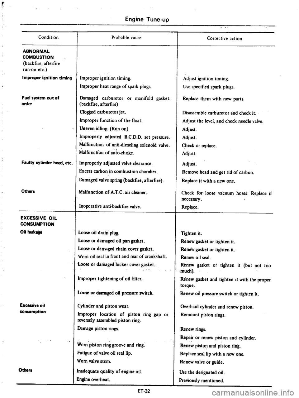
Condition
ABNORMAL
COMBUSTION
backfue
afterflre
run
on
etc
Improper
ignition
timing
Fuel
system
out
of
order
Faulty
cylinder
head
etc
Others
EXCESSIVE
OIL
CONSUMPTION
Oilloak
Excessi
lo
oil
consumption
Others
Engine
Tune
up
probable
cause
Improper
ignition
timing
Improper
heat
range
of
spark
plugs
Damaged
carburetor
or
manifold
gasket
backfue
afterfire
Clol
l
ed
carburetor
jet
Improper
function
of
the
float
Uneven
idling
Run
on
Improperly
adjusted
B
C
D
D
set
pressure
Malfunction
of
anti
dieseling
solenoid
valve
Malfunction
of
auio
choke
Improperly
adjusted
valve
clearance
Excess
carbon
in
combustion
chamber
Damaged
valve
spring
backfire
afterflre
Malfunction
of
A
T
C
air
cleaner
Inoperative
ariti
backfue
valve
Loose
oil
drain
plug
Loose
or
damaged
oil
pan
gasket
Loose
or
damaged
chain
cover
gasket
Worn
oil
seal
in
front
and
rear
of
crankshaft
Loose
or
damaged
locker
cover
gasket
Improper
tightening
of
oil
filter
Loose
or
damaged
oil
pressure
switch
Cylinder
and
pioton
wear
Improper
location
of
piston
ring
gap
or
reversely
assembled
piston
ring
Damage
piston
rings
Worn
piston
ring
groove
and
ring
Fatigue
of
valve
oil
seal
lip
Worn
valve
stem
Inadequate
quality
of
engine
oil
Engine
overheat
ET32
Corrective
action
Adjust
ignition
timing
Use
specified
spark
plugs
Replace
them
with
new
parts
Disassemble
carburetor
and
check
it
Adjust
the
level
and
check
needle
valve
Adjust
Adjust
Check
or
replace
Adjust
Adjust
Remove
head
and
get
rid
of
carbon
Replace
it
with
a
new
one
Check
for
loose
vacuum
hoses
Replace
if
necessary
Replape
Tighten
it
Renew
gasket
or
tighten
it
Renew
gasket
or
tighten
it
Renew
oil
seal
Renew
gasket
or
tighten
it
but
not
too
much
Renew
gasket
and
tighten
it
with
the
proper
torque
Renew
oil
pressure
switch
or
tighten
it
Overhaul
cylinder
and
renew
piston
Remoun
t
piston
rings
Renew
rings
Repair
or
renew
piston
and
cylinder
Renew
piston
and
piston
ring
Replace
seal
lip
with
a
new
one
Renew
valve
or
guide
Use
the
designated
oil
Previously
mentioned
Page 102 of 537
r
AIR
CLEANER
1
Loosen
bolts
securing
air
cleaner
to
air
cleaner
bracket
2
Loosen
air
cleaner
lock
bolt
and
remove
air
cleaner
from
carburetor
Disconnect
the
following
hoses
when
dismounting
air
cleaner
Under
hood
air
inlet
hose
Hot
air
inlet
hose
Vacuum
hose
Sensor
to
intake
manifold
Vacuum
hose
Sensor
to
vacuum
motor
Vacuum
hose
Idle
compensator
to
intake
manifold
Hose
Air
pump
to
air
cleaner
Hose
AB
valve
to
air
cleaner
Hose
Carburetor
to
air
cleaner
Blow
by
hose
Air
cleaner
to
rocker
cover
Hose
Air
control
vaive
to
air
cleaner
California
models
only
3
To
install
reverse
the
removal
procedure
INSPECTION
1
AIR
CLEANER
ELEMENT
Viscous
paper
type
air
cleaner
ele
ment
does
not
require
any
cleaning
operation
until
it
is
replaced
periodi
cally
Brushing
or
blasting
operation
will
cause
clogging
and
result
in
enrich
ment
of
carburetor
mixture
and
should
never
be
conducted
For
reo
placement
interval
of
air
cleaner
ele
ment
refer
to
Maintenance
Sched
ule
2
HOT
AIR
CONTROL
SYSTEM
In
warm
weather
it
is
difficult
to
find
out
malfunction
of
hot
air
control
system
In
cold
wea
thee
however
malfunction
of
air
control
valve
due
to
disconnection
or
deterioration
of
vacu
um
hose
between
intake
manifold
and
vacuum
motor
and
insufficient
dura
bility
of
air
control
valve
will
cause
insufficient
automatic
control
opera
tion
for
intake
air
and
result
in
engine
disorder
including
I
Stall
or
hesitation
of
engine
oper
ation
2
Increase
in
fuel
consumption
3
uck
of
power
Engine
Fuel
These
phenomena
reveal
malfunc
tion
of
hot
air
control
system
If
these
phenomena
should
occur
check
hot
air
control
system
as
described
in
the
following
before
carrying
out
inspec
tion
of
carburetor
2
1
Vacuum
hose
Intake
manifold
to
3
way
connec
tor
3
way
connector
to
temperature
sensor
3
way
connector
to
idle
com
pensator
temperature
sensor
to
vacu
um
motor
I
Check
that
vacuum
hoses
are
se
curely
connected
in
correct
postion
2
Check
each
hose
for
cracks
or
distortion
hose
clip
for
condition
Note
Vacuum
hose
position
R
H
side
of
Nissan
mark
on
the
top
of
sensor
is
for
intake
manifold
L
U
side
of
the
mark
is
for
vacuum
motor
2
2
Vacuum
motor
I
With
engine
stopped
disconnect
fresh
air
duct
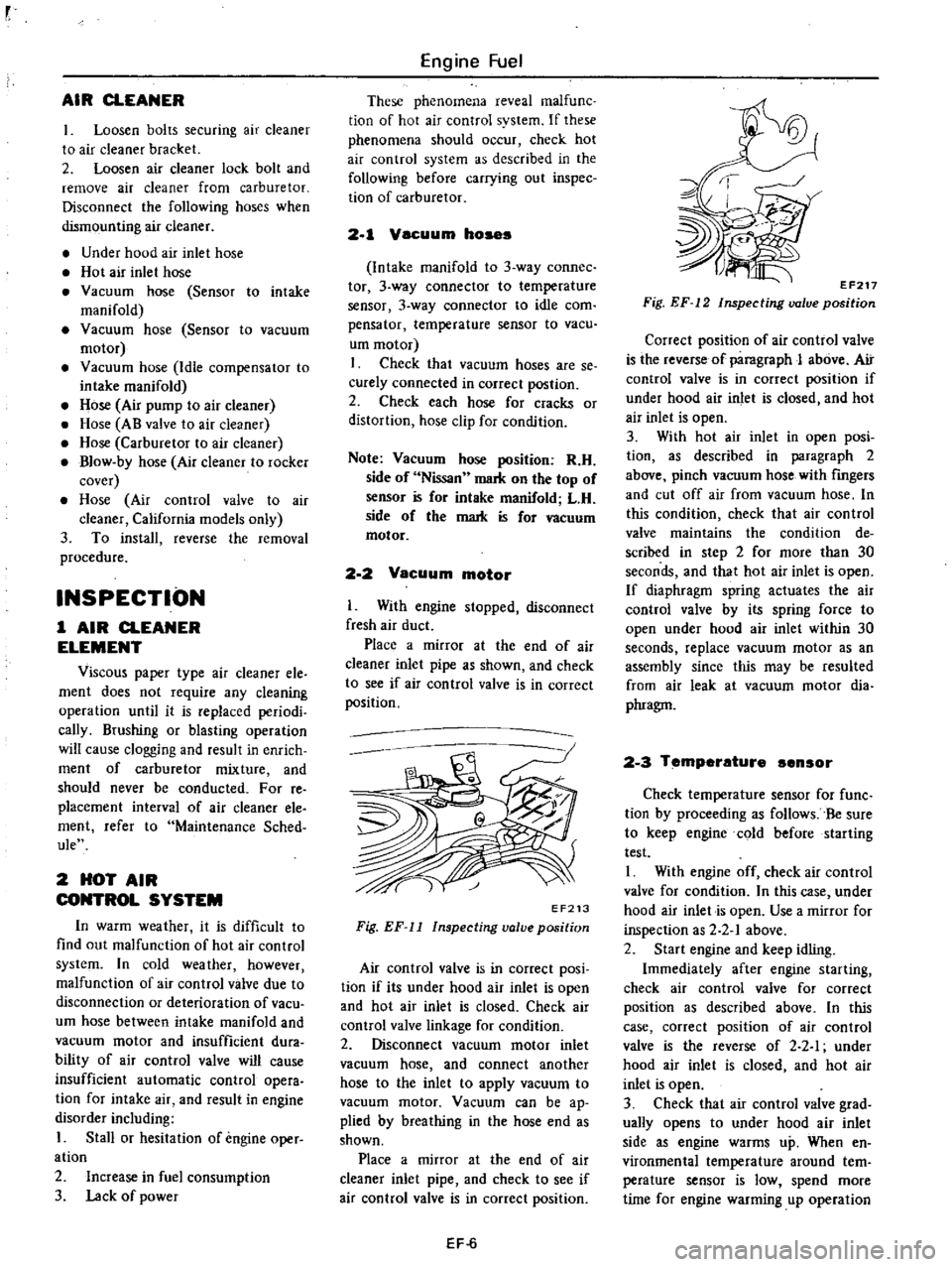
Place
a
mirror
at
the
end
of
air
cleaner
inlet
pipe
as
shown
and
check
to
see
if
air
con
trol
valve
is
in
correct
position
EF213
Fig
EF
11
Inspecting
valve
position
Air
control
valve
is
in
correct
posi
tion
if
its
under
hood
air
inlet
is
open
and
hot
air
inlet
is
closed
Check
air
control
valve
linkage
for
condition
2
Disconnect
vacuum
motor
inlet
vacuum
hose
and
connect
another
hose
to
the
inlet
to
apply
vacuum
to
vacuum
motor
Vacuum
can
be
ap
plied
by
breathing
in
the
hose
end
as
shown
Place
a
mirror
at
the
end
of
air
cleaner
inlet
pipe
and
check
to
see
if
air
control
valve
is
in
correct
position
EF
6
EF217
Fig
EF
12
Inspecting
valve
position
Correct
position
of
air
control
valve
is
the
reverse
of
paragraph
J
above
Air
control
valve
is
in
correct
position
if
under
hood
air
inlet
is
closed
and
hot
air
inlet
is
open
3
With
hot
air
inlet
in
open
posi
tion
as
described
in
paragraph
2
above
pinch
vacuum
hose
with
fingers
and
cut
off
air
from
vacuum
hose
In
this
condition
check
that
air
control
valve
maintains
the
condition
de
scribed
in
step
2
for
more
than
30
seconds
and
that
hot
air
inlet
is
open
If
diaphragm
spring
actuates
the
air
control
valve
by
its
spring
force
to
open
under
hood
air
inlet
within
30
seconds
replace
vacuum
motor
as
an
assembly
since
this
may
be
resulted
from
air
leak
at
vacuum
motor
dia
phragm
2
3
Temperature
ensor
Check
temperature
sensor
for
func
tion
by
proceeding
as
follows
Be
sure
to
keep
engine
cold
before
starting
test
I
With
engine
off
check
air
control
valve
for
condition
In
this
case
under
hood
air
inlet
is
open
Use
a
mirror
for
inspection
as
2
2
1
above
2
Start
engine
and
keep
idling
Immediately
after
engine
starting
check
air
control
valve
for
correct
position
as
described
above
In
this
case
correct
position
of
air
control
valve
is
the
reverse
of
2
2
I
under
hood
air
inlet
is
closed
and
hot
air
inlet
is
open
3
Check
that
air
control
valve
grad
ually
opens
to
under
hood
air
inlet
side
as
engine
warms
up
When
en
vironmental
temperature
around
tern
perature
sensor
is
low
spend
more
time
for
engine
warming
up
operation
Page 113 of 537
Step
system
The
construction
of
this
system
may
correspond
to
the
idling
and
slow
system
of
the
primary
system
Tlris
system
aims
at
the
proper
filling
up
of
the
gap
when
fuel
supply
is
transferred
from
the
primary
system
to
the
secondary
one
The
step
port
is
located
near
the
secondary
throttle
valve
edge
in
its
fully
closed
state
Secondary
switchover
mechanism
The
secondary
throttle
valve
is
linked
to
the
diaphragm
which
is
actuated
by
the
vacuum
created
in
the
venturi
A
vacuum
jet
is
provided
at
each
of
the
primary
and
secondary
venturies
and
the
composite
vacuum
of
these
jets
actuates
the
diaphragm
As
the
linkage
causes
the
secondary
throttle
valve
to
close
until
the
prima
ry
throttle
valve
opening
reaches
ap
proximately
500
fuel
consumption
during
normal
operation
is
not
exces
sive
During
high
speed
running
as
shown
in
Figure
EF
28
as
the
vacuum
at
the
venturi
is
increased
the
dia
phragm
is
pulled
against
the
diaphragm
spring
force
and
then
secondary
throt
tie
valve
is
opened
The
other
side
during
low
speed
running
as
the
primary
throttle
valve
opening
does
not
reach
500
the
secondary
throttle
valve
is
locked
to
close
completely
by
the
locking
arm
which
is
interlocked
with
primary
throttle
arm
by
linkage
When
the
primary
throttle
valve
opening
reaches
wider
position
than
500
the
secondary
throttle
valve
is
ready
to
open
because
the
locking
arm
revolves
and
leaves
from
the
se
condary
throttle
arm
Engine
Fuel
HI
h
speed
circuit
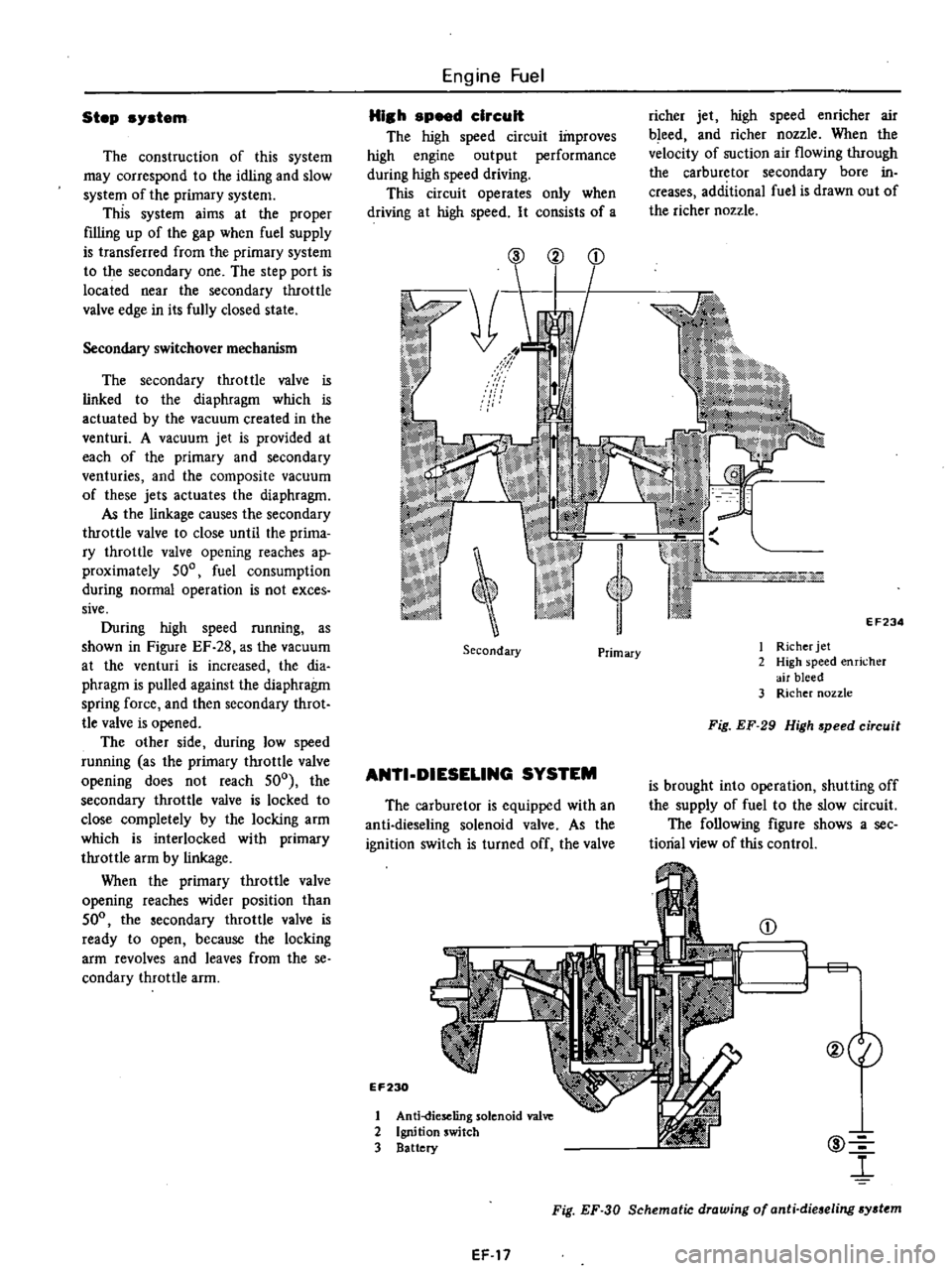
The
high
speed
circuit
improves
high
engine
output
performance
during
high
speed
driving
This
circuit
operates
only
when
driving
at
high
speed
It
consists
of
a
richer
jet
high
speed
enricher
air
bleed
and
richer
nozzle
When
the
velocity
of
suction
air
flowing
through
the
carburetor
secondary
bore
in
creases
additional
fuel
is
drawn
out
of
the
richer
nozzle
@
2
EF234
Secondary
I
Richer
jet
2
High
speed
enricher
air
bleed
3
Richer
nozzle
Primary
Fig
EF
29
High
speed
circuit
ANTI
DIESELlNG
SYSTEM
is
brought
into
operation
shutting
off
the
supply
of
fuel
to
the
slow
circuit
The
following
figure
shows
a
see
tiorial
view
of
this
control
The
carburetor
is
equipped
with
an
anti
dieseling
solenoid
valve
As
the
ignition
switch
is
turned
off
the
valve
EF230
@
l
CD
1
1
g
@eI
1
Anti
dieseling
solenoid
va1
2
Ignition
switch
3
Battery
Fig
EF
30
Schematic
drawing
of
anti
dieseling
sydtm
EF
17
Page 114 of 537
FLOAT
SYSTEM
There
IS
only
one
float
chamber
while
two
l
arburetor
systems
primary
Jnd
st
l
ondary
are
provided
Fuel
fed
from
the
fuel
pump
flows
through
the
filler
and
needle
valve
into
the
flo
t
chamber
A
constant
fuel
level
is
maintained
by
the
float
and
needle
valve
Because
of
the
inner
air
vent
type
of
the
float
chamber
ventilation
the
fuel
consumption
will
not
be
in
fluenced
by
some
dirt
accumulated
in
the
air
deaner
The
needle
valve
includes
special
hard
steel
ball
and
will
not
wear
for
all
its
considerably
long
use
Besides
the
inserrion
of
a
spring
wiU
prevent
the
flooding
at
rough
road
running
BOOST
CONTROLLED
DECELERATION
DEVICE
B
C
D
D
A
Boost
Controlled
Deceleration
Device
B
C
D
D
serves
to
reduce
the
hydrocarbons
He
emitted
from
en
gine
during
coasting
The
high
manifold
vacuum
during
coasting
prevents
the
mixture
from
complete
combustion
because
of
the
reduced
amount
of
mixture
per
cyl
inder
per
rotation
of
engine
with
the
result
that
a
large
amount
of
hydrocar
bons
is
emitted
into
tile
atmosphere
The
B
C
D
D
has
been
designed
to
correct
this
problem
It
opern
tes
as
follows
when
the
manifold
vacuum
exceeds
a
pre
Engine
Fuel
determined
value
the
B
C
D
D
intro
duces
an
additional
mixture
of
opti
mum
mixture
ratio
and
quantity
into
the
manifold
by
opening
a
separate
mixture
passage
in
the
carburetor
Complete
combustion
of
fuel
is
assist
ed
by
this
additional
mixture
and
the
amount
of
H
C
contained
in
exhaust
gases
is
dramatically
reduced
During
the
transition
period
from
coasting
to
idling
the
transmission
produces
a
signal
which
turns
on
the
vacuum
control
solenoid
valve
As
this
takes
place
the
valve
is
lifted
off
its
seat
opening
the
vacuum
chamber
to
the
atmosphere
The
mixture
control
valve
is
then
closed
returning
the
engine
to
the
predetermined
idling
speed
On
manual
transmission
models
this
system
consists
of
B
C
D
D
vacuo
urn
control
solenoid
valve
speed
de
tecting
switch
and
amplifier
On
automatic
transmission
models
it
consists
of
B
C
D
D
vacuum
con
trol
solenoid
valve
and
inhibitor
switch
B
C
D
D
operation
Diaphragm
I
Qj
monitors
the
mani
fold
vacuum
and
when
the
vacuum
exceeds
a
pre
fetermined
value
acts
so
as
to
open
the
vacuum
control
valve
@
This
causes
the
manifold
vacu
urn
to
be
introduced
into
the
second
vacuum
chamber
and
actuates
dia
phragm
ll@
When
diaphrngm
II
operates
the
mixture
control
valve
@
opens
the
passage
and
introduces
the
additional
mixture
into
the
manifold
EF
18
The
amount
of
the
mixture
is
con
trolled
by
the
servo
action
of
the
mixture
control
valve
CID
and
vacuum
control
valve
@
so
that
the
manifold
vacuum
may
be
kept
at
the
pre
determined
value
The
amount
of
mixture
depends
mainly
upon
the
coasting
air
bleed
II@
while
the
mixture
ratio
is
deter
mined
by
the
coasting
jet
@
and
coasting
air
bleed
@
See
Figure
EF
31
Vacuum
control
solenoid
valve
operation
Manual
transmission
models
The
vacuum
control
solenoid
valve
is
con
troDed
by
a
speed
detecting
switch
that
is
actuated
by
the
speed
ometer
needle
As
the
vehicle
speed
falls
below
10
MPH
this
switch
is
activated
pro
ducing
a
signal
This
signal
actuates
the
amplifier
to
open
the
vacuum
control
solenoid
valve
Automatic
transmission
models
When
the
shift
lever
is
in
N
or
P
position
the
inhibitor
switch
mounted
on
the
transmission
turns
on
to
open
the
vacuum
control
solenoid
valve
Page 132 of 537
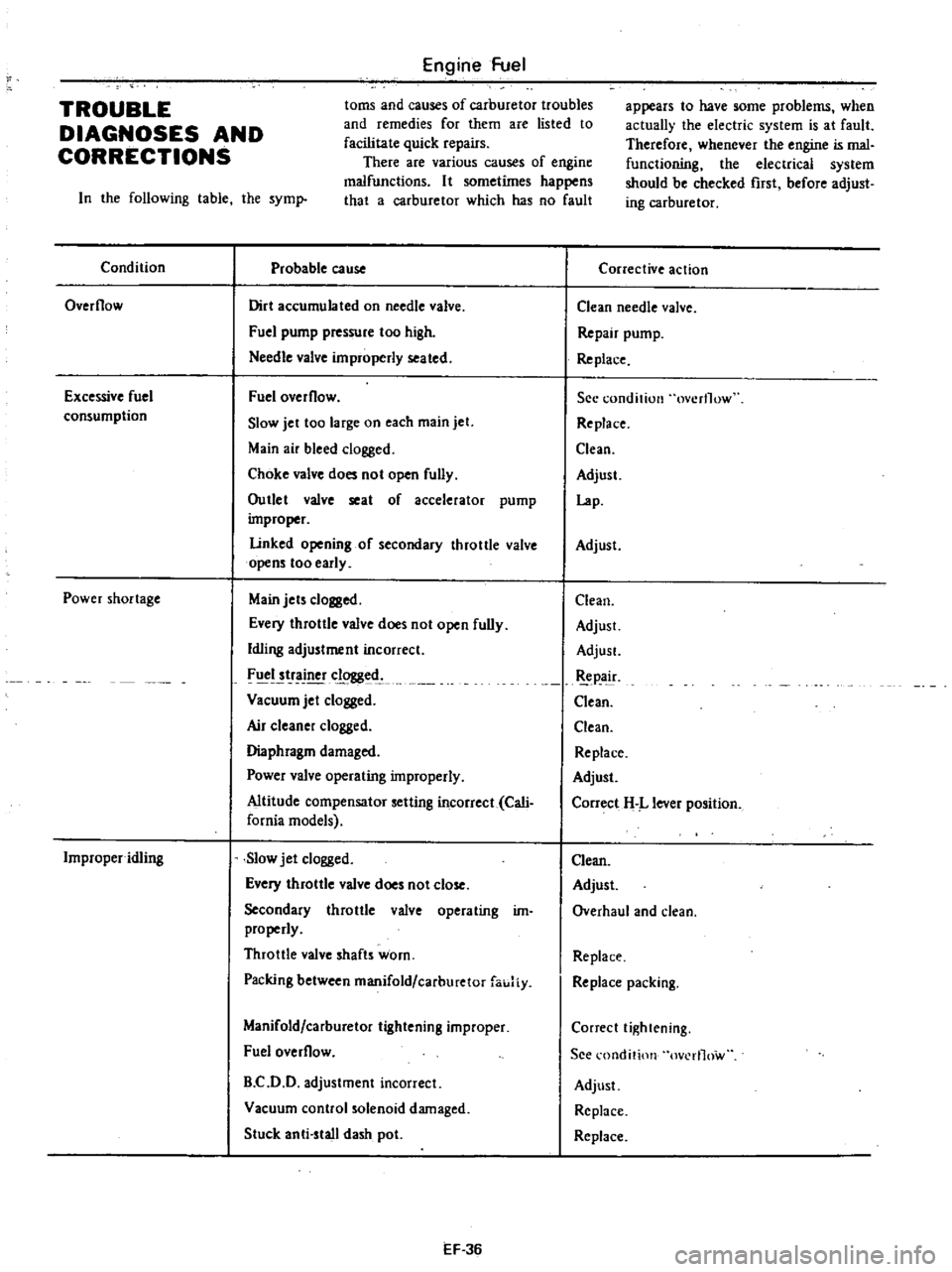
Engine
Fuel
toms
and
causes
of
carburetor
troubles
and
remedies
for
them
are
listed
to
facilitate
quick
repairs
There
are
various
causes
of
engine
malfunctions
It
sometimes
happens
that
a
carburetor
which
has
no
fault
TROUBLE
DIAGNOSES
AND
CORRECTIONS
In
the
following
table
the
syml
Condition
Probable
cause
Overflow
Dirt
accumulated
on
needle
valve
Fuel
pump
pressure
too
high
Needle
valve
improperly
seated
Excessive
fuel
consumption
Fuel
overflow
Slow
jet
too
large
on
each
main
jet
Main
air
bleed
clogged
Choke
valve
does
not
open
fully
Outlet
valve
seat
of
accelerator
pump
improper
Linked
opening
of
secondary
throttle
valve
opens
too
early
Power
shortage
Main
jets
clogged
Every
throttle
valve
does
not
open
fully
Idling
adjustment
incorrect
FIICI
tr
clogged
Vacuum
jet
clogged
Air
c1eane
clogged
Diaphragm
damaged
Power
valve
operating
improperly
Altitude
compensator
setting
incorrect
Cali
fornia
models
Improper
idling
Slow
jet
clogged
Every
throttle
valve
does
not
close
Secondary
throttle
valve
operating
im
properly
Throttle
valve
shafts
worn
Packing
between
manifold
carburetor
fauJiy
Manifold
carburetor
tightening
improper
Fuel
overflow
B
C
D
D
adjustment
incorrect
Vacuum
control
solenoid
damaged
Stuck
anti
stall
dash
pot
EF
36
appears
to
have
some
problems
when
actually
the
electric
system
is
at
fault
Therefore
whenever
the
engine
is
mal
functioning
the
electrical
system
should
be
checked
rust
before
adjust
ing
carburetor
Corrective
action
Clean
needle
valve
Repair
pump
Re
place
See
condition
overflow
Replace
Clean
Adjust
Lap
Adjust
Clean
Adjust
AdjusL
pa
ir
Clean
Clean
Replace
Adjust
Correct
H
L
lever
position
Clean
Adjust
Overhaul
and
clean
Replace
Replace
packing
Correct
tightening
See
l
ondition
ov
rl1ow
Adjust
Replace
Replace