service reset DATSUN PICK-UP 1977 Service Manual
[x] Cancel search | Manufacturer: DATSUN, Model Year: 1977, Model line: PICK-UP, Model: DATSUN PICK-UP 1977Pages: 537, PDF Size: 35.48 MB
Page 155 of 537

j
EC231
Thermal
vacuum
valva
o
o
m
Emission
Control
System
0
o
o
o
l
l
@
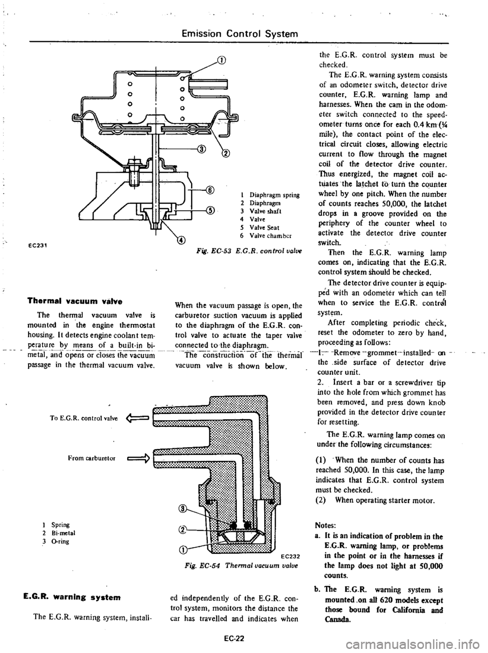
The
thermal
vacuum
valve
is
mounted
in
the
engine
thermostat
housing
It
detects
engine
coolan
t
tem
perature
by
means
of
a
built
in
bi
metal
and
opensor
closes
the
vacuum
passage
in
the
thermal
vacuum
valve
mt
li
t
00
t
EC232
Fig
EC
54
Thennal
vacuum
valve
To
E
G
R
control
valve
From
carburetor
1
Spring
2
Bi
metal
3
O
ring
E
G
R
warning
system
The
E
G
R
warning
system
install
1
Diaphragm
spring
2
Diaphragm
3
Valve
shaft
4
Valve
5
Valve
Seat
6
Valve
cham
ber
Fig
EC
53
E
G
R
control
value
When
the
vacuum
passage
is
open
the
carburetor
suction
vacuum
is
applied
to
the
diaphragm
of
the
E
G
R
con
trol
valve
to
actuate
the
taper
valve
connected
to
the
diaphragm
theconsiiiictlo
nlie
thermal
vacuum
valve
is
shown
below
ed
independently
of
the
E
G
R
con
trol
system
monitors
the
distance
the
car
has
travelled
and
indicates
when
EC
22
the
E
G
R
control
system
must
be
checked
The
E
G
R
warning
system
consists
of
an
odometer
switch
detector
drive
counter
E
G
R
warning
lamp
and
harnesses
When
the
earn
in
the
odom
eter
switch
connected
to
the
speed
ometer
turns
once
for
each
OAkm
4
mile
the
contact
point
of
the
elec
trica
circuit
closes
allowing
electric
current
to
flow
through
the
magnet
coil
of
the
detector
drive
counter
Thus
energized
the
magnet
coil
ac
Wates
the
latchet
to
turn
the
c
unter
wheel
by
one
pitch
When
the
number
of
counts
reaches
50
000
the
latchet
drops
in
a
groove
provided
on
the
periphery
of
the
counter
wheel
to
activate
the
detector
drive
counter
switch
Then
the
E
G
R
warning
lamp
comes
on
indicating
that
the
E
G
R
control
system
Should
be
checked
The
detector
drive
coun
teT
is
equip
ped
with
an
odometer
which
can
tell
when
to
service
the
E
G
R
contr0
I
system
After
completing
periodic
check
reset
the
odometer
to
zero
by
hand
proceeding
as
follows
1
Remove
grommet
installed
on
the
side
surface
of
detector
drive
counter
unit
2
insert
a
bar
or
a
screwdriver
tip
into
the
hole
from
which
grommet
has
been
removed
and
press
down
knob
provided
in
the
detector
drive
counter
for
resetting
The
E
G
R
warning
lamp
comes
on
under
the
following
circumstances
1
When
the
number
of
counts
has
reached
50
000
In
this
case
the
lamp
indicates
that
E
G
R
control
system
must
be
checked
2
When
operating
starter
motor
Notes
a
It
is
an
indication
of
problem
in
the
E
G
R
warning
lamp
or
problems
in
the
point
or
in
the
harnesses
if
the
lamp
does
not
light
at
50
000
counts
b
The
E
G
R
warning
system
is
mounted
on
all
620
models
except
those
bound
for
California
and
Canada
Page 214 of 537

DESCRIPTION
INSPECTION
CLEANING
AND
REGAP
DESCRIPTION
The
spark
plugs
are
of
the
conven
tional
type
having
14
mm
0
551
in
threads
The
spark
plug
gaps
are
1
0
to
1
1
mm
0
039
to
0
043
in
on
Cali
fomia
models
and
0
8
to
0
9
mm
0
031
to
0
035
in
on
non
California
models
The
inspection
and
cleaning
should
be
made
every
suitable
mainte
nance
period
If
necessary
replace
Note
All
spark
plugs
installed
on
an
engine
must
be
of
the
same
brand
and
the
same
number
of
heat
range
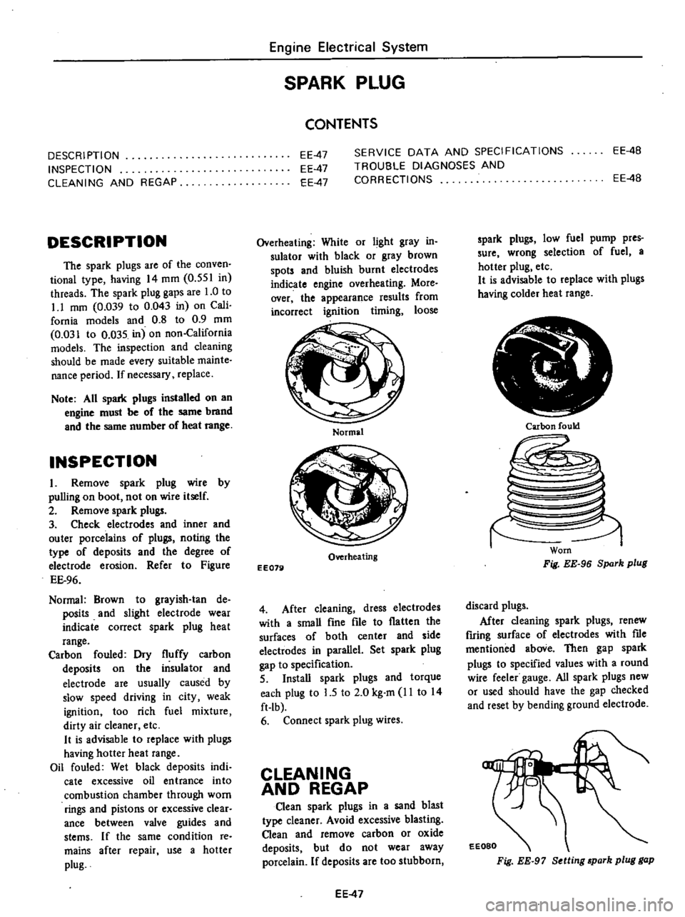
INSPECTION
L
Remove
spark
plug
wire
by
pulling
on
boot
not
on
wire
itself
2
Remove
spark
plugs
3
Check
electrodes
and
inner
and
outer
porcelains
of
plugs
noting
the
type
of
deposits
and
the
degree
of
electrode
erosion
Refer
to
Figure
EE
96
Normal
Brown
to
grayish
tan
de
posits
and
slight
electrode
wear
indicate
correct
spark
plug
heat
range
Carbon
fouled
Dry
fluffy
carbon
deposits
on
the
insulator
and
electrode
are
usually
caused
by
slow
speed
driving
in
city
weak
ignition
too
rich
fuel
mixture
dirty
air
cleaner
etc
It
is
advisable
to
replace
with
plugs
having
hotter
heat
range
Oil
fouled
Wet
black
deposits
indi
cate
excessive
oil
entrance
into
combustion
chamber
through
worn
rings
and
pistons
or
excessive
clear
ance
between
valve
guides
and
stems
If
the
same
condition
re
mains
after
repair
use
a
hotter
plug
Engine
Electrical
System
SPARK
PLUG
CONTENTS
EE
4B
EE
47
EE
47
EE
47
SERVICE
DATA
AND
SPECIFICATIONS
TROUBLE
DIAGNOSES
AND
CORRECTIONS
EE
4B
Overheating
White
or
light
gray
in
sulator
with
black
or
gray
brown
spots
and
bluish
burnt
electrodes
indicate
engine
overheating
More
over
the
appearance
results
from
incorrect
ignition
timing
loose
Normal
Overheating
EE079
4
After
cleaning
dress
electrodes
with
a
smaU
fine
file
to
flatten
the
surfaces
of
both
center
and
side
electwdes
in
parallel
Set
spark
plug
gap
to
specification
5
InstaU
spark
plugs
and
torque
each
plug
to
L5
to
2
0
kg
m
11
to
14
ft
Ib
6
Connect
spark
plug
wires
CLEANING
AND
REGAP
Clean
spark
plugs
in
a
sand
blast
type
cleaner
Avoid
excessive
blasting
Clean
and
remove
carbon
or
oxide
deposits
but
do
not
wear
away
porcelain
If
deposits
are
too
stubborn
EE
47
spark
plugs
low
fuel
pump
pres
sure
wrong
selection
of
fuel
a
hotter
plug
etc
It
is
advisable
to
replace
with
plugs
having
colder
heat
range
Ir
i
Carbon
fould
Worn
Fig
EE
96
Spark
plug
discard
plugs
After
cleaning
spark
plugs
renew
firing
surface
of
electrodes
with
me
mentioned
aboVe
Then
gap
spark
plugs
to
specified
values
with
a
round
wire
feeler
gauge
All
spark
plugs
new
or
used
should
have
the
gap
checked
and
reset
by
bending
ground
electrode
EEOBO
Fig
EE
97
Setting
park
plug
gap