clock setting DATSUN PICK-UP 1977 Service Manual
[x] Cancel search | Manufacturer: DATSUN, Model Year: 1977, Model line: PICK-UP, Model: DATSUN PICK-UP 1977Pages: 537, PDF Size: 35.48 MB
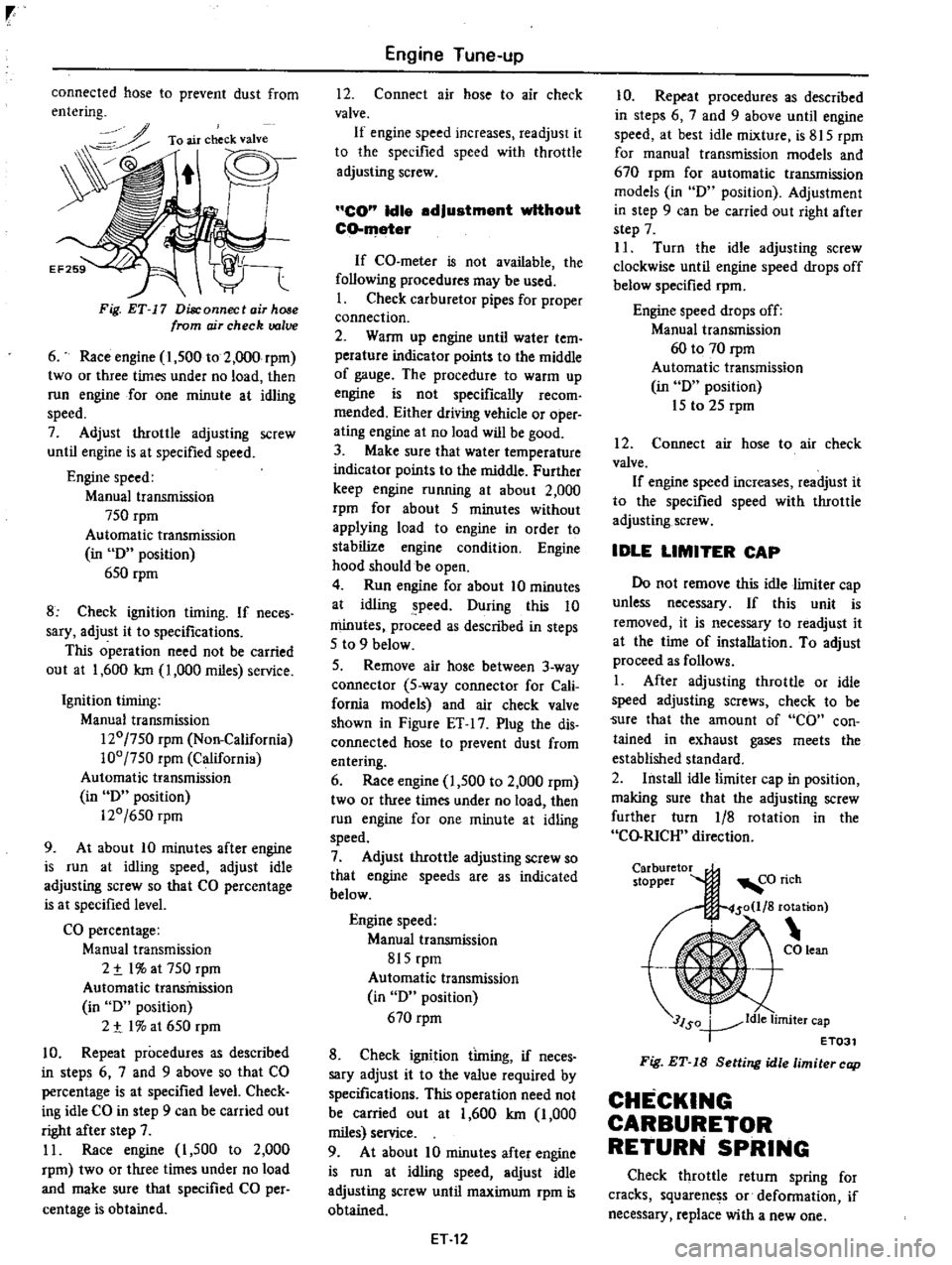
Page 24 of 537

r
connected
hose
to
prevent
dust
from
entering
To
air
check
valve
Fig
ET
17
Disconnect
air
hose
from
ojr
check
valve
6
Race
engine
1
500
to
2
000
rpm
two
or
three
times
under
no
load
then
run
engine
for
one
minute
at
idling
speed
7
Adjust
throttle
adjusting
screw
until
engine
is
at
specified
speed
Engine
speed
Manual
transmission
750
rpm
Automatic
transmission
in
D
position
650
rpm
8
Check
ignition
timing
If
neces
sary
adjust
it
to
specifications
This
operation
need
not
be
carried
out
at
1
600
Ian
1
000
miles
service
Ignition
timing
Manual
transmission
120
750
rpm
Non
California
100
750
rpm
California
Automatic
transmission
in
D
position
120
650
rpm
9
At
about
10
minutes
after
engine
is
run
at
idling
speed
adjust
idle
adjusting
screw
so
that
CO
percentage
is
at
specified
level
CO
percentage
Manual
transmission
2
t
I
at
750
rpm
Automatic
transmission
in
D
position
2
t
I
at
650
rpm
10
Repeat
procedures
as
described
in
steps
6
7
and
9
above
so
that
CO
percentage
is
at
specified
level
Check
ing
idle
CO
in
step
9
can
be
carried
out
right
after
step
7
11
Race
engine
I
500
to
2
000
rpm
two
or
three
times
under
no
load
and
make
sure
that
specified
CO
per
centage
is
obtained
Engine
Tune
up
12
Connect
air
hose
to
air
check
valve
If
engine
speed
increases
readjust
it
to
the
specified
speed
with
throttle
adjusting
screw
CO
Idle
adjustment
without
CO
meter
If
CO
meter
is
not
available
the
following
procedures
may
be
used
I
Check
carburetor
pipes
for
proper
connection
2
Wann
up
engine
until
water
tern
perature
indicator
points
to
the
middle
of
gauge
The
procedure
to
warm
up
engine
is
not
specifically
recom
mended
Either
driving
vehicle
or
oper
ating
engine
at
no
load
will
be
good
3
Make
sure
that
water
temperature
indicator
points
to
the
middle
Further
keep
engine
running
at
about
2
000
rpm
for
about
5
minutes
without
applying
load
to
engine
in
order
to
stabilize
engine
condition
Engine
hood
should
be
open
4
Run
engine
for
about
10
minutes
at
idling
peed
During
this
10
minutes
proceed
as
described
in
steps
5
to
9
below
5
Remove
air
hose
between
3
way
connector
5
way
connector
for
Cali
fornia
modeis
and
air
check
valve
shown
in
Figure
ET
17
Plug
the
dis
connected
hose
to
prevent
dust
from
entering
6
Race
engine
1
500
to
2
000
rpm
two
or
three
times
under
no
load
then
run
engine
for
one
minute
at
idling
speed
7
Adjust
throttle
adjusting
screw
so
that
engine
speeds
are
as
indicated
below
Engine
speed
Manual
transmission
815
rpm
Automatic
transmission
in
D
position
670
rpm
8
Check
ignition
timing
if
neces
sary
adjust
it
to
the
value
required
by
specifications
This
operation
need
not
be
carried
out
at
1
600
Ian
1
000
miles
service
9
At
about
10
minutes
after
engine
is
run
at
idling
speed
adjust
idle
adjusting
screw
until
maximum
rpm
is
obtained
ET
12
10
Repeat
procedures
as
described
in
steps
6
7
and
9
above
until
engine
speed
at
best
idle
mixture
is
815
rpm
for
manual
transmission
models
and
670
rpm
for
automatic
transmission
models
in
D
position
Adjustment
in
step
9
can
be
carried
out
right
after
step
7
II
Turn
the
idle
adjusting
screw
clockwise
until
engine
speed
drops
off
below
specified
rpm
Engine
speed
drops
off
Manual
transmission
60
to
70
rpm
Automatic
transmission
in
D
position
15
to
25
rpm
12
Connect
air
hose
to
air
check
valve
If
engine
speed
increases
readjust
it
to
the
specified
speed
with
throttle
adjusting
screw
IDLE
LIMITER
CAP
Do
not
remove
this
idle
limiter
cap
unless
necessary
If
this
unit
is
removed
it
is
necessary
to
readjust
it
at
the
time
of
installation
To
adjust
proceed
as
follows
1
After
adjusting
throttle
or
idle
speed
adjusting
screws
check
to
be
Sure
that
the
amount
of
CO
con
tained
in
exhaust
gases
meets
the
established
standard
2
Install
idle
limiter
cap
in
position
making
sure
that
the
adjusting
screw
further
turn
1
8
rotation
in
the
CO
RICH
direction
Carburetor
stopper
3lSo
ldle
limiter
cap
T
ET031
Fig
ET
18
Setting
idle
limiter
cap
CHECKING
CARBURETOR
RETURN
SPRING
Check
throttle
return
spring
for
cracks
squarene
s
or
defonnation
if
necessary
replace
with
a
new
one
Page 30 of 537

r
ADJUSTMENT
OF
SET
PRESSURE
OF
BOOST
CONTROLLED
DECELERATION
DEVICE
B
C
D
D
Generally
it
is
unnecessary
to
ad
just
the
B
C
D
D
however
if
it
should
become
necessary
to
adjust
it
the
procedure
is
as
follows
Prepare
the
foUowlnB
tools
I
Tachometer
to
measure
the
en
gine
speed
while
idling
and
a
screw
driver
2
A
vacuum
gauge
connecting
pipe
Note
A
qui
k
response
type
boost
gauge
such
as
Bourdon
s
type
is
recommended
a
mercury
type
manometer
should
not
be
used
To
properly
set
the
B
C
D
D
set
pressure
proceed
as
follows
I
Remove
the
harness
of
solenoid
valve
TO
D
D
solenrod
VT
FJ
1
B
C
D
D
solenni
valve
harness
J
ri
y
EF262
F
g
ET
32
Removing
harneS5
of
solenoid
valve
2
Connect
rubber
hose
between
vacuum
gauge
and
intake
manifold
as
shown
Fig
ET
33
Connecting
vacuum
gauge
3
Warm
up
the
engine
until
it
is
heated
to
operating
temperature
Then
adjust
the
engine
at
normal
Engine
Tune
up
idling
setting
Refer
to
the
item
Idling
Adjustment
in
page
ET
II
Idling
engine
speed
Manual
transmission
750
rpm
Automatic
transmission
in
D
position
650
rpm
4
Run
the
engine
under
no
load
Increase
engine
speed
to
3
000
to
3
500
rpm
then
quickly
close
throttle
valve
5
At
the
time
the
manifold
vacuum
pressure
increases
abruptly
to
600
mmHg
23
62
inHg
or
above
and
then
gradually
decreases
to
the
level
set
at
idling
6
Check
that
the
B
C
D
D
set
pres
sure
is
within
the
specified
pressure
Specified
pressure
0
m
sea
level
and
760
mmHg
30
inHg
atmos
pheric
pressure
Manual
transmission
510
to
550
mmHg
20
1
to
21
7
inHg
Automatic
transmission
490
to
530
mmHg
19
3
to
20
9
inHg
Note
When
checking
the
set
pressure
of
B
C
D
D
find
the
specified
set
pressure
in
Figure
IT
36
from
the
atmospheric
pressure
and
altitutde
of
the
given
location
For
example
if
a
manual
transmis
sion
model
vehicle
is
located
at
an
altitude
of
1
000
m
3
280
ft
the
specified
set
preSsure
for
B
C
D
D
445
mmHg
17
5
inHg
7
If
it
is
higher
than
the
set
level
turn
the
adjusting
screw
counter
clockwise
or
nut
clockwise
until
correct
adjustment
is
made
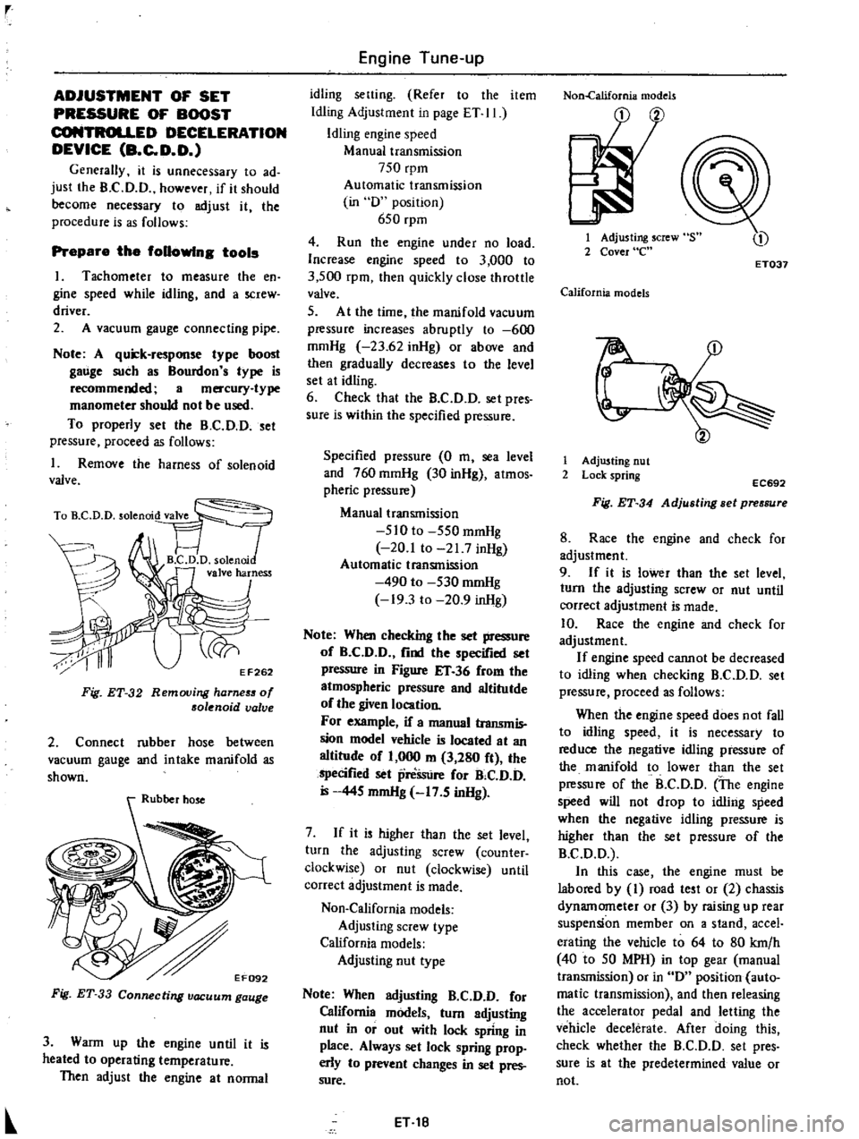
Non
California
models
Adjusting
screw
type
California
models
Adjusting
nut
type
Note
When
adjusting
B
C
D
D
for
California
models
turn
adjusting
nut
in
or
out
with
lock
spring
in
place
Always
set
lock
spring
prop
erly
to
prevent
changes
in
set
pres
sure
ET
18
Non
california
models
1
Adjusting
screw
2
Cover
e
ET037
California
models
r
1
Adjusting
nut
2
Lock
spring
EC692
Fig
ET
34
Adjusting
Bet
pressure
8
Race
the
engine
and
check
for
adjustment
9
If
it
is
lower
than
the
set
level
turn
the
adjusting
screw
or
nut
until
correct
adjustment
is
made
10
Race
the
engine
and
check
for
adjustment
If
engine
speed
cannot
be
decreased
to
idling
when
checking
B
C
D
D
set
pressure
proceed
as
follows
When
the
engine
speed
does
not
fall
to
idling
speed
it
is
necessary
to
reduce
the
negative
idling
pressure
of
the
manifold
to
lower
than
the
set
pressure
of
the
B
C
D
D
The
engine
speed
will
not
drop
to
idling
speed
when
the
negative
idling
pressure
is
higher
than
the
set
pressure
of
the
B
C
D
D
In
this
case
the
engine
must
be
labored
by
I
road
test
or
2
chassis
dynamometer
or
3
by
raising
up
rear
suspension
member
on
a
stand
accel
erating
the
vehicle
to
64
to
80
krn
h
40
to
50
MPH
in
top
gear
manual
transmission
or
in
D
position
auto
matic
transmission
and
then
releasing
the
accelerator
pedal
and
letting
the
vehicle
decelerate
After
doing
this
check
whether
the
B
C
D
D
set
pres
sure
is
at
the
predetermined
value
or
not
Page 118 of 537

rpm
two
or
three
iimes
under
no
load
and
make
sure
that
specified
CO
per
centage
is
obtained
12
Connect
air
hose
to
air
check
valve
If
engine
speed
increases
readjust
it
to
the
specified
speed
with
throttle
adjustingsqew
CO
idle
edJustment
without
CO
meter
If
CO
meter
is
not
available
the
following
procedures
may
be
used
L
Check
carburetor
pipes
for
proper
connection
2
Warm
up
engine
until
water
tem
perature
indicator
points
to
the
middle
of
gauge
The
procedure
to
warm
up
engine
is
not
specifically
recom
mended
Either
driving
vehicle
or
oper
ating
engine
at
no
load
will
be
good
3
Make
sure
that
water
temperature
indicator
points
to
the
middle
Further
keep
engine
running
at
about
2
000
rpm
for
about
5
minutes
without
applying
load
to
engine
in
order
to
stabilize
engine
condition
Engine
hood
should
be
open
4
Run
engine
for
about
10
minutes
at
idling
speed
During
this
10
minutes
proceed
as
described
in
steps
5
to
9
below
5
Remove
air
hose
between
3
way
connector
5
way
connector
for
Cali
fornia
models
and
air
check
valve
shown
in
Figure
EF
35
Plug
the
dis
connected
hose
19
prevent
dust
from
entering
6
Race
engine
1
500
to
2
000
rpm
two
or
three
times
under
no
load
then
run
engine
for
one
minute
at
idling
speed
7
Adjust
throttle
adjusting
screw
so
that
engine
speeds
are
as
indicated
below
Engine
speed
Manual
transmission
815
rpm
Automatic
transmission
in
D
position
670
rpm
8
Check
ignition
timing
if
neces
sary
adjust
it
to
the
value
required
by
specifications
This
operation
need
not
be
carried
out
at
1
600
km
1
000
miles
service
9
At
about
10
minutes
after
engine
Engine
Fuel
is
run
at
idling
speed
adjust
idle
adjusting
screw
until
maximum
rpm
is
obtained
10
Repeat
procedures
as
described
in
steps
6
7
and
9
above
until
engine
speed
at
best
idle
mixture
is
815
rpm
for
manual
transmission
models
and
670
rpm
for
automatic
transmission
models
in
D
position
Adjustment
in
step
9
can
be
carried
out
right
after
step
7
11
Turn
the
idle
adjusting
screw
clockwise
until
engine
speed
drops
off
below
specified
rpm
Engine
speed
drops
off
Manual
transmission
60
to
70
rpm
Automatic
transmission
in
D
position
15
to
25
rpm
12
Connect
air
hose
to
air
check
valve
If
engine
speed
increases
readjust
it
to
the
specified
speed
with
throttle
adjusting
screw
Idle
limiter
cep
Do
not
remove
this
idle
limiter
cap
unless
necessary
If
this
unit
is
re
moved
it
must
be
readjusted
at
lime
of
installation
To
adjust
proceed
as
follows
I
After
adjusting
throttle
or
idle
speed
adjusting
screw
check
to
be
sure
that
the
amount
of
CO
contained
in
exhaust
gases
meets
the
established
standard
2
Install
idle
limiter
cap
in
position
making
sure
that
the
adjusting
screw
can
rotate
another
1
8
turn
in
the
CO
RICH
direction
Carbo
to
per
CO
rich
450
lIS
rotation
t
CO
lean
J
SQ
dl
lim
ET031
1
e
Iter
cap
Fig
EF
36
Setting
idle
limiter
cap
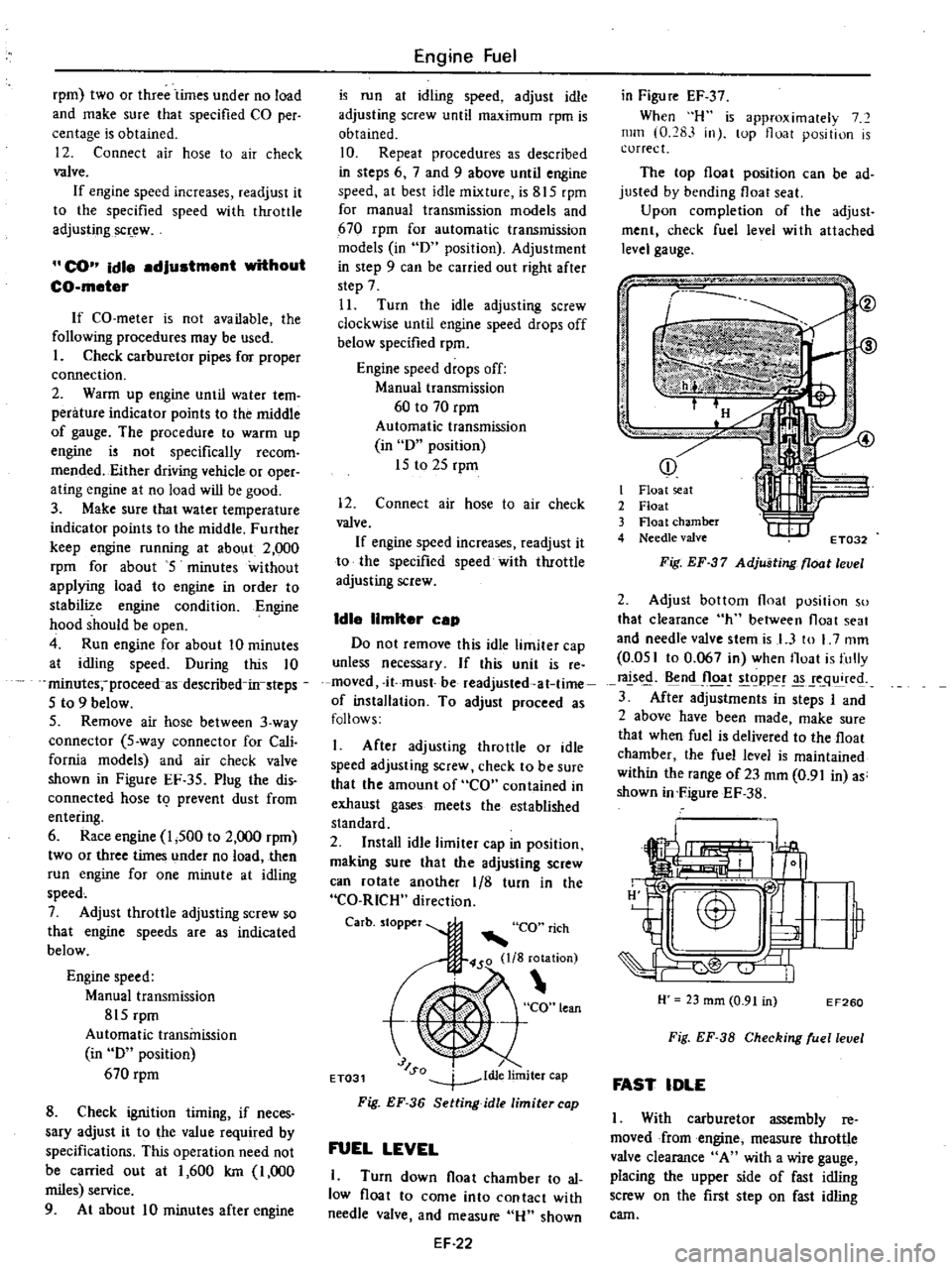
FUEL
LEVEL
1
Turn
down
float
chamber
to
al
low
float
to
come
into
contact
with
needle
valve
and
measure
Hu
shown
EF
22
in
Figu
re
EF
37
When
H
is
approximalely
7
mill
0
283
in
lOp
float
position
is
correct
The
top
float
position
can
be
ad
justed
by
bending
float
seat
Upon
completion
of
the
adjust
ment
check
fuel
level
wi
th
attached
level
gauge
p
j
i
I
it
I
Float
seat
2
Float
3
Float
chamber
4
Needle
valve
t
I
IIf
ET032
Fig
EF
37
Adjusting
float
level
2
Adjust
bottom
float
position
so
that
clearance
h
between
float
seat
and
needle
valve
stemis
I
3
to
L
7
mm
0
051
to
0
067
in
when
Iloat
is
fully
rals
n
Jloa
t
goppe
q
re
3
After
adjustments
in
steps
I
and
2
above
have
been
made
make
sure
that
when
fuel
is
delivered
to
the
float
chamber
the
fuel
level
is
maintained
within
the
range
of23
mm
0
91
in
as
shown
in
FigureEF
38
H
23
mm
0
91
in
EF260
Fig
EF
38
Checking
ruellevel
FAST
IDLE
I
With
carburetor
assembly
reo
moved
from
engine
measure
throttle
valve
clearance
A
with
a
wire
gauge
placing
the
upper
side
of
fast
idling
screw
on
the
first
step
on
fast
idling
cam