high beam DATSUN PICK-UP 1977 Service Manual
[x] Cancel search | Manufacturer: DATSUN, Model Year: 1977, Model line: PICK-UP, Model: DATSUN PICK-UP 1977Pages: 537, PDF Size: 35.48 MB
Page 186 of 537

Engine
Electrical
System
ALTERNATOR
TEST
Before
conducting
an
alternator
test
make
sure
th
tthe
battery
is
fully
charged
A
30
V
olt
voltmeter
and
suitable
test
probes
3re
necessary
for
the
test
Set
up
a
test
circuit
as
shown
in
Figure
EE45
and
test
auernator
in
the
manner
indica
ted
in
the
flow
chart
below
1
Disconnect
connectors
at
alternator
2
Connect
A
terminal
to
F
terminal
3
Connect
one
test
probe
from
voltmeter
positive
terminal
to
A
terminal
Connect
the
other
test
probe
to
ground
Make
sure
that
voltmeter
registers
battery
voltage
4
Turn
on
headlights
and
switch
to
High
Beam
5
Start
engine
6
Increase
engine
speed
gradually
until
it
is
approximately
1
100
rpm
and
take
the
voltmeter
reading
Measured
value
Below
12
5
Volts
Alternator
is
in
trouble
remove
and
check
it
for
condition
Measured
value
Over
12
5
Volts
Alternator
is
in
good
condition
Notes
a
Do
Dot
run
engine
at
the
speed
of
more
than
1
100
rpm
while
test
is
being
conducted
on
alternator
b
Do
not
race
engine
i
9
l
IV
I
Battery
EE052
Voltmeter
Fig
EE
45
Testing
alternator
SERVICE
DATA
AND
SPECIFICATIONS
Nominal
rating
V
A
LT138
IB
LTl35
36B
For
air
conditioner
1235
12
38
Negative
Negative
1
000
1
000
28
2
500
30
2
500
35
5
000
38
5
000
2
25
2
25
More
than
7
5
0
295
More
than
7
5
0
295
255
to
345
255
to
345
9
0
to
12
2
9
0
to
12
2
More
than
30
1
181
More
than
30
1
181
EE
19
Type
Ground
polarity
Minimum
revolution
when
generating
14V
with
no
load
rpm
Hot
output
current
Nrpm
Pulley
ratio
Brush
Length
Spring
pressure
mm
in
gr
oz
Slip
ring
outer
diameter
mm
in
Page 451 of 537

To
adjust
vertical
aim
use
adjusting
screw
on
upper
side
of
headlamp
and
to
adjust
horizontal
aim
use
adjusting
screw
on
side
of
head
lamp
Notes
Before
making
headlarnp
aiming
ad
justment
observe
the
foUowing
in
structions
Body
Electrical
System
a
Keep
aU
tires
inflated
to
correct
pressures
b
Place
vehicle
and
tester
on
the
same
flat
surface
c
See
that
there
is
no
load
in
vehicle
I
Gasoline
radiator
and
engine
oil
pan
filled
up
to
correct
levels
2
Without
passenger
When
performing
headlamp
aiming
adjustment
use
an
aiming
device
aiming
wall
screen
or
headlamp
tester
For
operating
instructions
of
any
aimer
refer
to
respective
operation
manuals
supplied
with
the
unit
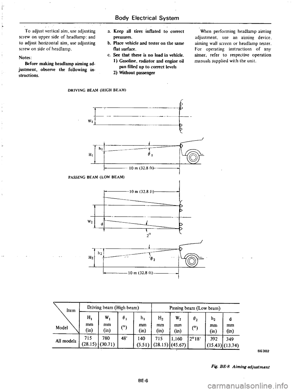
DRIVING
BEAM
HIGH
BEAM
L
wt
H
G
hi
i
iiI
PASSING
BEAM
LOW
BEAM
10
m
32
8
ft
W2
H2
10
m
02
8
n
d
20
h2
I
02
I
I
f
10
m
32
8
ft
Driving
beam
High
beam
Passing
beam
Low
beam
HI
WI
01
mm
mm
CO
in
in
I
715
780
48
All
models
28
15
30
71
hI
H2
W2
h2
O2
d
mm
mm
mm
in
in
in
0
140
I
715
11
160
12018
5
51
28
15
45
67
mm
mm
in
in
392
349
is
43
13
74
BE302
Fig
BE
8
Aiming
adjustment
BE
6
Page 457 of 537

Body
Electrical
System
BULB
SPECIFICATIONS
Item
Wattage
Candlepower
Headlamp
Inner
Outer
37
5W
37
5
S0W
Front
combination
lamp
Turn
signal
and
parking
lamp
23
8W
32
3C
Side
marker
lamp
Front
Rear
8W
4C
8W
4C
Rear
combination
lamp
Turn
signal
lamp
A
B
Tail
lamp
B
C
Stop
lamp
A
B
Back
up
lamp
D
A
23W
32C
B
23j8W
32j3C
C
8W
4C
D
23W
32C
7
SW
6C
License
plate
lamp
Engine
compartment
lamp
6W
Room
lamp
5W
Combination
meter
illurnina
tion
17W
iC
x3
Knob
illumination
lamp
3
4W
2C
Heater
control
illumination
lamp
3
4W
2C
TROUBLEDIAGNOSE
AND
CORRECTIONS
HEADLAMP
Condition
Headlarnps
do
not
light
for
both
high
and
low
beams
High
beam
cannot
be
switched
to
low
beam
or
vice
versa
Probable
cause
Burnt
fuse
Loose
connection
or
open
circuit
Faulty
lighting
switch
Faulty
dimmer
switch
Faulty
light
relay
No
ground
Faulty
dimmer
switch
Faulty
light
relay
BE12
Bulb
SAE
trade
number
4001
4002
1034
67
67
1073
1034
67
1073
89
161
158
158
Corrective
action
Correct
cause
and
replace
fuse
Check
wiring
and
or
repair
connection
Conduct
continuity
test
and
replace
if
neces
sary
Check
light
relay
for
proper
operation
and
replace
if
necessary
Clean
and
tighten
ground
terminal
Conduct
continuity
test
and
replace
if
neces
sary
Check
light
relay
for
proper
operation
and
replace
if
necessary
Page 463 of 537

HAND
BRAKE
WARNING
LAMP
DESCRIPTION
The
hand
brake
warning
lamp
glows
when
the
hand
brake
is
applied
When
the
ignition
switch
is
set
to
ON
current
flows
from
the
ignition
switch
to
the
warning
lamp
When
the
hand
brake
is
applied
hand
brake
warning
switch
is
closed
and
warning
lamp
glows
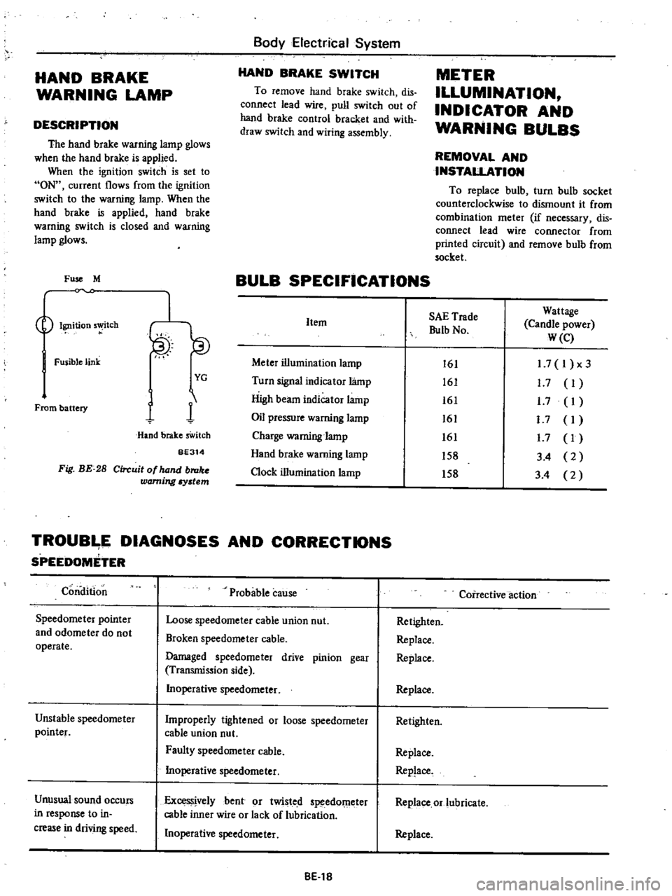
Fuse
M
Ignition
5
tch
Fusible
link
From
battery
I
YG
1
1
Hand
brake
sWitch
BE314
Fig
BE
28
Circuit
of
hand
broke
warning
Iystem
Body
Electrical
System
HAND
BRAKE
SWITCH
To
remove
hand
brake
switch
dis
connect
lead
wire
pull
switch
out
of
hand
brake
control
bracket
and
with
draw
switch
and
wiring
assembly
METER
ILLUMINATION
INDICATOR
AND
WARNING
BULBS
REMOVAL
AND
INSTALLATION
To
replace
bulb
turn
bulb
socket
counterclockwise
to
dismount
it
from
combination
meter
if
necessary
dis
connect
lead
wire
connector
from
printed
circuit
and
remove
bulb
from
socket
BULB
SPECIFICATIONS
Item
Meter
illumination
lamp
Turn
signal
indicator
lamp
High
beam
indicator
lamp
Oil
pressure
warning
lamp
Charge
warning
lamp
Hand
brake
warning
lamp
Clock
illumination
lamp
SAE
Trade
Bulb
No
Wattage
Candle
power
W
e
161
161
161
161
161
158
158
1
7
I
x3
1
7
I
1
7
I
I
7
I
1
7
I
3
4
2
3
4
2
TROUB
E
DIAGNOSES
AND
CORRECTIONS
SPEEDOMETER
Condition
Speedometer
pointer
and
odometer
do
not
operate
Unstable
speedometer
pointer
Unusual
sound
occurs
in
response
to
in
crease
in
driving
speed
Probable
cause
Loose
speedometer
cable
union
nut
Broken
speedometer
cable
Damaged
speedometer
drive
pinion
gear
Transmission
side
Inoperative
speedometer
Improperly
tightened
or
loose
speedometer
cable
union
nut
Faulty
speedometer
cable
Inoperative
speedometer
ExceS
jvelybent
or
twisted
speedOmeter
cable
inner
wire
or
lack
of
lubrication
Inoperative
speedometer
8El8
Coirective
action
Retighten
Replace
Replace
Replace
Retighten
Replace
Replace
Replace
or
lubricate
Replace