fuel pressure DATSUN PICK-UP 1977 Service Manual
[x] Cancel search | Manufacturer: DATSUN, Model Year: 1977, Model line: PICK-UP, Model: DATSUN PICK-UP 1977Pages: 537, PDF Size: 35.48 MB
Page 21 of 537
Yellow
line
Spark
delay
valve
to
distributor
Spark
delay
valve
to
vacuum
tube
Distributor
to
vacuum
tube
Vacuum
tube
to
carburetor
Vacuum
tube
to
canister
Green
line
Anti
backfire
valve
to
intake
mani
fold
Air
control
valve
to
emergency
air
relief
valve
Intake
manifold
to
vacuum
hose
connector
Intake
manifold
to
canister
CHECKING
ENGINE
COMPRESSION
COMPRESSION
PRESSURE
TEST
I
Warm
up
engine
sufficiently
2
Disconnect
all
spark
plugs
3
Disconnect
anti
dieseling
solenoid
valve
connector
4
Properly
attach
a
compression
tester
to
spark
plug
hole
in
cylinder
being
tested
Engine
Tune
up
I
ET010
Different
compression
in
two
or
more
cylinders
usually
indicates
an
improperly
seated
valve
or
broken
piston
ring
9
Low
compression
in
cylinders
can
result
from
worn
piston
rings
This
condition
may
usually
be
accompanied
by
excessive
fuel
consumption
TEST
RESULT
If
compression
in
one
or
more
cylinders
is
low
pour
a
small
quantity
of
engine
oil
into
cylinders
through
the
spark
plug
holes
and
retest
com
pression
I
If
adding
oil
increases
the
com
pression
pressure
the
chances
are
that
rings
are
faulty
2
If
pressure
stays
low
probable
cause
is
that
valve
is
sticking
or
seating
improperly
3
If
cylinder
compression
in
any
two
adjacent
cylinders
is
low
and
if
adding
oil
does
not
help
the
compres
sian
there
is
leakage
past
the
gasket
surface
Oil
and
water
in
combustion
cham
bers
can
result
from
leakage
IGNITION
AND
FUEL
SYSTEM
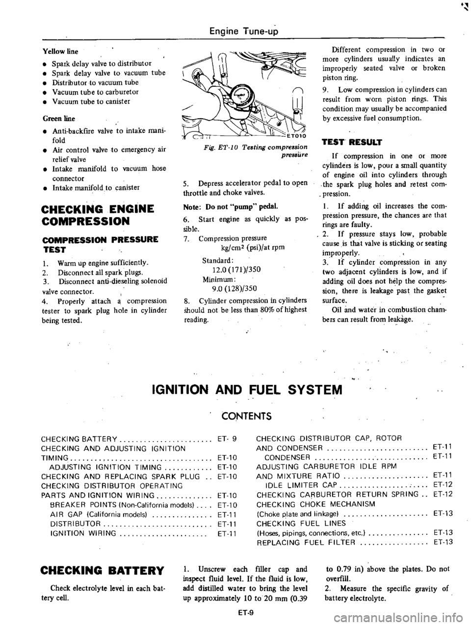
Fig
ET
10
Teding
compression
pressure
5
Depress
accelerator
pedal
to
open
throttle
and
choke
valves
Note
Do
not
pump
pedal
6
Start
engine
as
quickly
as
pos
sible
7
Compression
pressure
kg
cm2
psi
at
rpm
Standard
12
0
171
350
Minimum
9
0
128
350
8
Cylinder
compression
in
cylinders
Should
not
be
less
than
80
of
highest
reading
CONTENTS
CHECKING
BATTERY
ET
9
CHECKING
DISTRIBUTOR
CAP
ROTOR
CHECKING
AND
ADJUSTING
IGNITION
AND
CONDENSER
ET
11
TIMING
ET
10
CONDENSER
ET
11
ADJUSTING
IGNITION
TIMING
ET10
ADJUSTING
CARBURETOR
IDLE
RPM
CHECKING
AND
REPLACING
SPARK
PLUG
ETlO
AND
MIXTURE
RATIO
ET
11
CHECKING
DISTRIBUTOR
OPERATING
IDLE
LIMITER
CAP
ET
12
PARTS
AND
IGNITION
WIRING
ETlO
CHECKING
CARBURETOR
RETURN
SPRING
ET
12
BREAKER
POINTS
lNon
California
models
ET
10
CHECKING
CHOKE
MECHANISM
AI
R
GAP
lCalifornia
models
ET11
Choke
plate
and
linkage
ET13
DISTRIBUTOR
ET
11
CHECKING
FUEL
LINES
IGNITION
WIRING
ET
11
Hoses
pipings
connections
etc
ET
13
REPLACING
FUEL
FILTER
ET
13
CHECKING
BATTERY
Check
electrolyte
level
in
each
bat
tery
cell
I
Unscrew
each
filler
cap
and
inspect
fluid
level
If
the
fluid
is
low
add
distilled
water
to
bring
the
level
up
approximately
10
to
20
mm
0
39
H
9
to
0
79
in
above
the
plates
Do
not
overfill
2
Measure
the
specific
gravity
of
battery
electrolyte
Page 25 of 537
CHECKING
CHOKE
MECHANISM
Choke
plate
and
linkage
1
Check
choke
valve
and
mech
anism
for
free
operation
and
clean
or
replace
if
necessary
A
binding
can
result
from
petroleum
gum
formation
on
choke
shaft
or
from
damage
2
Check
bimetal
cover
setting
Index
mark
on
bimetal
cover
is
usually
set
at
center
of
scale
Note
Always
align
the
index
mark
on
bimetal
cover
with
the
center
index
mark
on
choke
housing
3
Every
day
before
starting
engine
depress
the
accelerator
P
dal
to
see
if
choke
valve
is
closed
automatically
If
it
fails
to
be
closed
the
chances
are
that
link
movement
is
unsmooth
Engine
Tune
up
or
that
bimetal
is
out
of
order
Refer
to
Carburetor
in
Section
EF
CHECKING
FUEL
LINES
Hoses
pipings
connections
etc
Check
fuel
lines
for
loose
con
nections
cracks
and
deterioration
Retighten
loose
connections
and
re
place
any
damaged
or
deformed
parts
REPLACING
FUEL
FILTER
Check
for
a
contaminated
filter
and
water
deposit
All
engines
use
a
replaceable
cartridge
type
fuel
filter
as
an
as
sembly
@
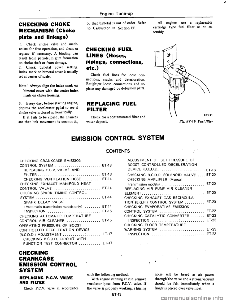
Fig
ET
19
Fuel
filler
ET011
EMISSION
CONTROL
SYSTEM
CHECKING
CRANKCASE
EMISSION
CONTROL
SYSTEM
REPLACING
P
C
V
VALVE
AND
FILTER
CHECKING
VENTILATION
HOSE
CHECKING
EXHAUST
MANIFOLD
HEAT
CONTROL
VALVE
CHECKING
SPARK
TIMING
CONTROL
SYSTEM
SPARK
DELAY
VALVE
Automatic
transmission
models
only
INSPECTION
CHECKING
AUTOMATIC
TEMPERATURE
CONTROL
AIR
CLEANER
OPERATING
PRESSURE
OF
BOOST
CONTROLLED
DECELERATION
DEVICE
B
CD
D
I
ADJUSTMENT
CHECKING
B
C
DD
CIRCUIT
WITH
FUNCTION
TEST
CONNECTOR
CHECKING
CRANKCASE
EMISSION
CONTROL
SYSTEM
REPLACING
P
C
V
VALVE
AND
FILTER
Check
P
C
V
valve
in
accordance
CONTENTS
ET
13
ET
13
ET
14
ET
14
ET
14
ET
14
ET
15
ET
15
ET
17
ET
17
ADJUSTMENT
OF
SET
PRESSURE
OF
BOOST
CONTROLLED
DECELERATION
DEVICE
B
CD
D
CHECKING
B
C
D
D
SOLENOID
VALVE
CHECKING
AMPLIFIER
Manual
transmission
models
REPLACING
AIR
PUMP
AIR
CLEANER
ELEMENT
CHECKING
EXHAUST
GAS
RECIRCULA
TION
E
G
R
CONTROL
SYSTEM
CHECKING
EVAPORATIVE
EMISSION
CONTROL
SYSTEM
CHECKING
CATALYTIC
CONVERTER
INSPECTION
CHECKING
FLOOR
TEMPERATURE
WARNING
SYSTEM
INSPECTION
with
the
following
method
With
engine
running
at
idle
remove
ventilator
ose
from
P
C
V
valve
If
the
valve
is
properly
working
a
hissing
ET
13
ET
18
ET
20
ET
20
ET
20
ET
20
ET
22
ET
23
ET
23
ET
23
ET
23
noise
will
be
heard
as
air
passes
through
the
valve
and
a
strong
vacuum
should
be
felt
immediately
when
a
finger
is
placed
over
valve
inlet
Page 34 of 537
r
EC350
Fig
ET
43
Cleanill
l
E
G
R
control
lJ
Jlue
Thermal
VBCuum
valve
Dismount
thermal
vacuum
valve
from
engine
Note
Before
dismounting
drain
e
gine
coolant
from
engine
Apply
vacuum
to
thermal
vacuum
valve
and
check
to
be
sure
that
ther
mal
vacuum
valve
opens
or
closes
in
response
to
engine
coolant
tempera
lurt
i1
i
iYCl
lt
lt
U
Thermal
vacuum
valve
should
open
at
a
temperature
of
57
to
630C
134
to
1450F
completing
the
vacuum
passage
Note
Do
not
aUow
water
to
get
inside
the
thermal
vacuum
valve
EC
242
Fig
ET
44
Checkill
lthermallXlCuum
valve
Engine
Tune
up
CHECKING
EVAPORATIVE
EMISSION
CONTROL
SYSTEM
Vapor
Rnes
and
fuel
vepor
control
valve
Checking
fuel
tank
vapor
liquid
separator
and
vapor
vent
line
I
Check
all
hoses
and
fuel
tank
roler
cap
2
Disconnect
the
vapor
vent
line
connecting
carbon
canister
to
vapor
liquid
separator
3
Connect
a
3
way
connector
a
manometer
and
a
cock
or
an
equiva
lent
3
way
charge
cock
to
the
end
of
the
vent
line
4
Supply
fresh
air
into
the
vapor
vent
line
through
the
cock
little
by
little
until
pressure
becomes
368
mmH20
14
5
inH20
5
Shut
the
cock
completely
and
leave
it
unattended
6
After
2
5
minutes
measure
the
height
of
the
liquid
in
the
manometer
7
Variation
of
height
should
remain
with
25
mm
l20
0
98
inH20
8
When
filler
cap
does
not
close
completely
the
height
should
drop
to
zero
in
a
short
time
9
I
f
the
height
does
not
drop
to
zero
in
a
short
time
when
filler
cap
is
removed
it
is
the
cause
of
a
stuffy
hose
Note
In
case
the
vent
line
is
stuffy
the
breathing
in
fuel
tank
is
not
thoroughly
made
thl
causing
in
suffICient
delivery
of
fuel
to
engine
or
vapor
lock
It
must
therefore
be
repaired
or
replaced
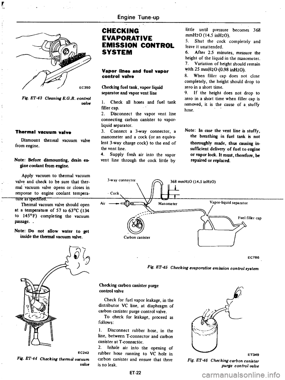
3
way
connectoT
36
mmH20
14
5
inH20
c
s
I
W
@
Carbon
canister
r
EC786
Fig
ET
45
Checking
evaporative
emission
control
By
tem
Checking
carbon
canister
purge
control
valve
Check
for
fuel
vapor
leakage
in
the
distributor
VC
line
at
diaphragm
of
carhon
canister
purge
control
valve
To
check
for
leakage
proceed
as
follows
1
Disconnect
rubber
hose
in
the
line
between
T
connector
and
carbon
canister
at
T
connector
2
Inhale
air
into
the
opening
of
rubber
hose
running
to
VC
hole
in
carbon
canister
and
ensure
that
there
is
no
leak
ET
22
I
I
L
I
ET349
Fig
ET
46
Checking
carbon
cani
ter
purge
control
valve
Page 42 of 537
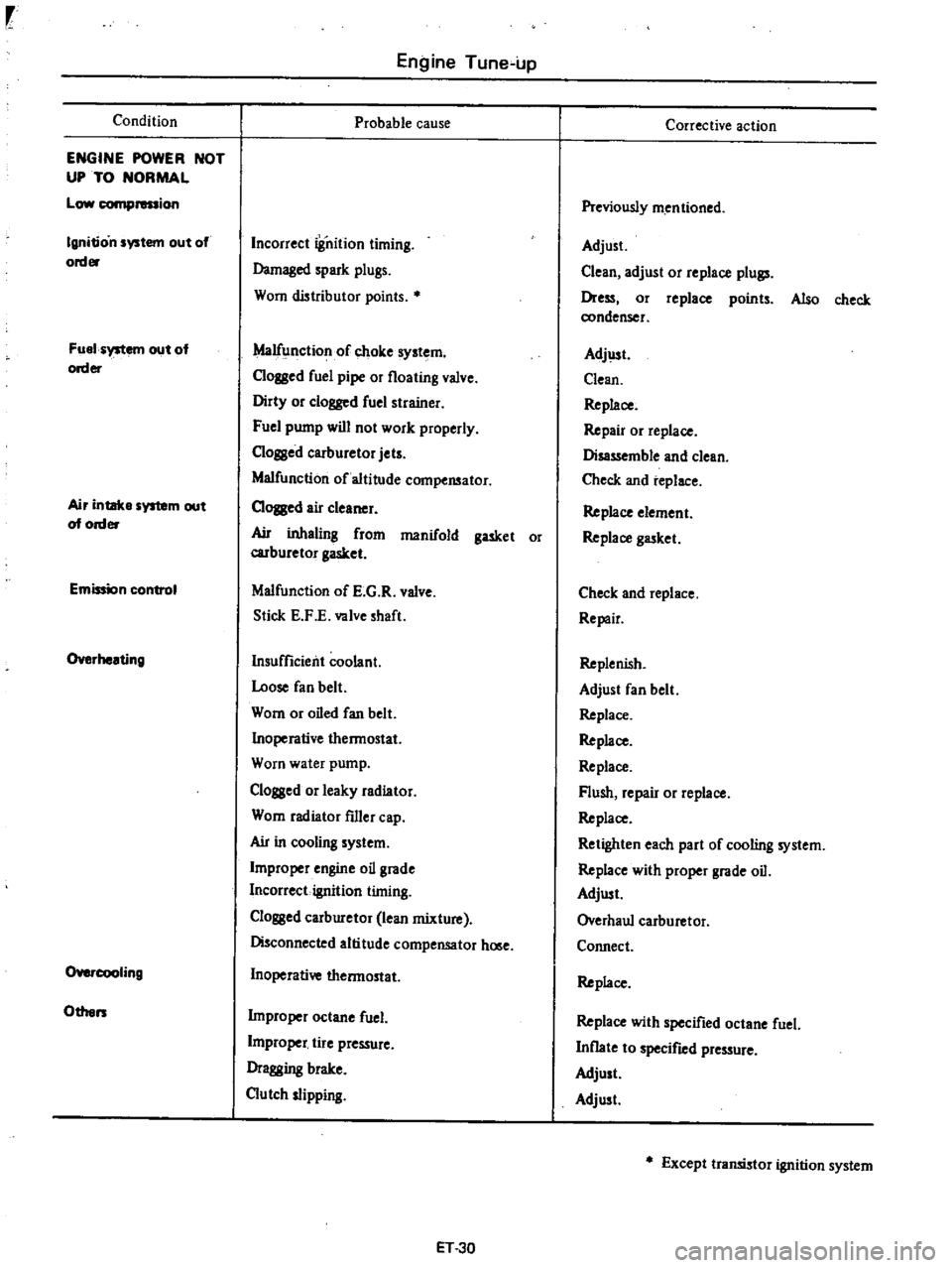
Condition
ENGINE
POWER
NOT
UP
TO
NORMAL
Low
compression
Ignition
system
out
of
order
Fuel
system
out
of
order
Air
intake
system
out
of
order
Emission
control
Overheating
O
cooIing
Others
Engine
Tune
up
Probable
cause
Incorrect
iSnition
timing
Damaged
spark
plugs
Worn
distributor
points
Malfunction
of
choke
system
Clogged
fuel
pipe
or
floating
valve
Dirty
or
clogged
fuel
strainer
Fuel
pump
will
not
work
properly
C10ssed
carburetor
jets
Malfunction
of
altitude
compensator
CIOJBed
air
cleaner
Ail
inhaling
from
manifold
gasket
or
carburetor
gasket
Malfunction
of
E
G
R
valve
Stick
E
F
E
valve
shaft
Insufficient
coolant
Loose
fan
belt
Worn
or
oiled
fan
belt
Inoperative
thermostat
Worn
water
pump
Clogged
or
leaky
radiator
Worn
radiator
filler
cap
Ail
in
cooling
system
Improper
engine
oil
grade
Incorrect
ignition
timing
Clossed
carburetor
lean
mixture
Disconnected
altitude
compensator
hOlle
Inoperative
thermostat
Improper
octane
fuel
L
j
tire
pressure
Dragging
brake
Clutch
slipping
ET
30
Corrective
action
Previously
mentioned
Adjust
Clean
adjust
or
replace
plull
Dress
or
replace
points
Also
check
condenser
Adj
lst
Clean
Replace
Repair
or
replace
Disassemble
and
clean
Check
and
replace
Replace
element
Replace
gasket
Check
and
replace
Repair
Replenish
Adjust
fan
belt
Replace
Replace
Replace
Flush
repair
or
replace
Replace
Retighten
each
part
of
cooling
system
Replace
with
proper
grade
oil
Adjust
Overhaul
carburetor
Connect
Replace
Replace
with
specified
octane
fuel
Inflate
to
specified
pressure
Adjust
Adjust
Except
transistor
ignition
system
Page 44 of 537
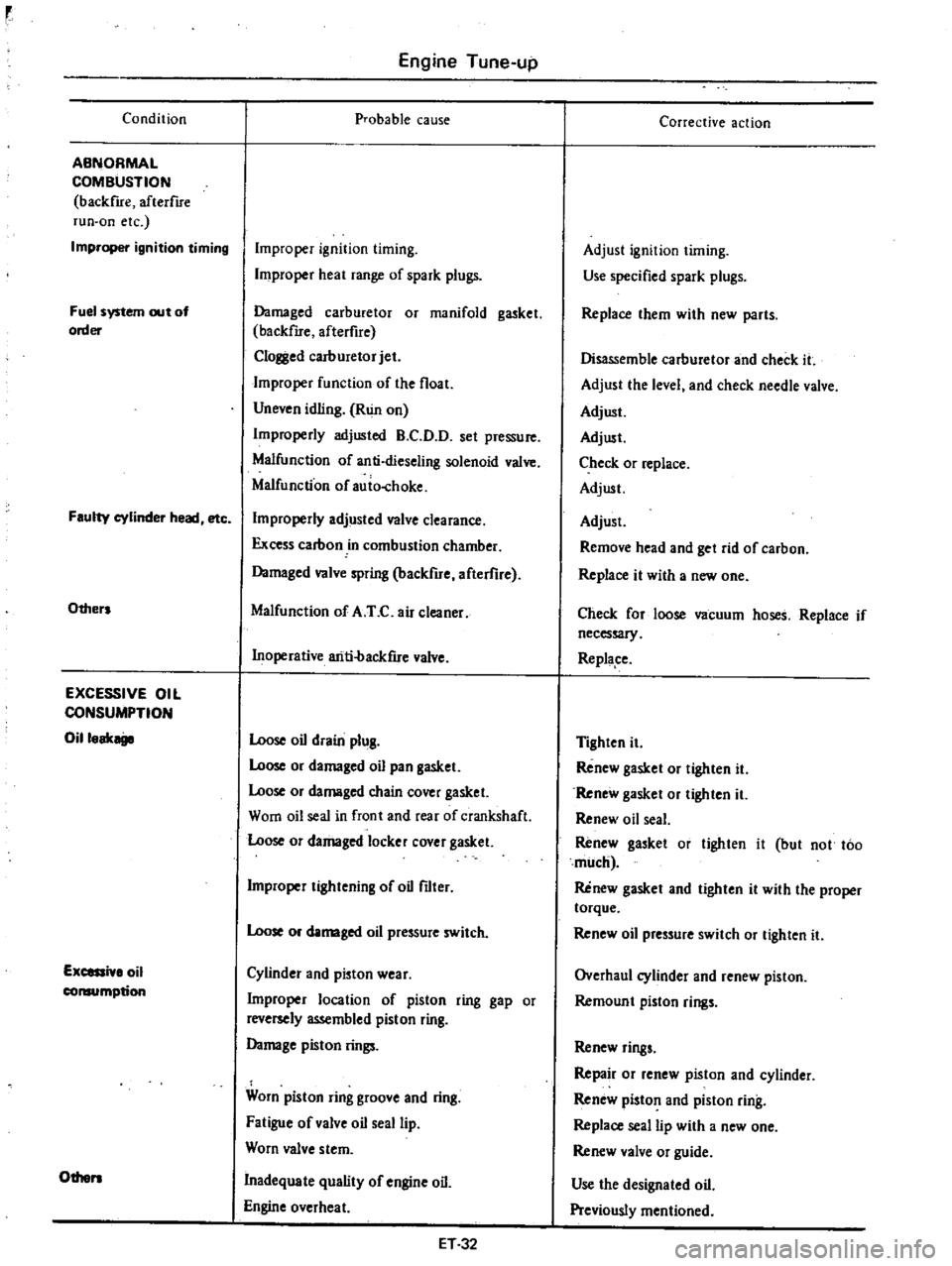
Condition
ABNORMAL
COMBUSTION
backfue
afterflre
run
on
etc
Improper
ignition
timing
Fuel
system
out
of
order
Faulty
cylinder
head
etc
Others
EXCESSIVE
OIL
CONSUMPTION
Oilloak
Excessi
lo
oil
consumption
Others
Engine
Tune
up
probable
cause
Improper
ignition
timing
Improper
heat
range
of
spark
plugs
Damaged
carburetor
or
manifold
gasket
backfue
afterfire
Clol
l
ed
carburetor
jet
Improper
function
of
the
float
Uneven
idling
Run
on
Improperly
adjusted
B
C
D
D
set
pressure
Malfunction
of
anti
dieseling
solenoid
valve
Malfunction
of
auio
choke
Improperly
adjusted
valve
clearance
Excess
carbon
in
combustion
chamber
Damaged
valve
spring
backfire
afterflre
Malfunction
of
A
T
C
air
cleaner
Inoperative
ariti
backfue
valve
Loose
oil
drain
plug
Loose
or
damaged
oil
pan
gasket
Loose
or
damaged
chain
cover
gasket
Worn
oil
seal
in
front
and
rear
of
crankshaft
Loose
or
damaged
locker
cover
gasket
Improper
tightening
of
oil
filter
Loose
or
damaged
oil
pressure
switch
Cylinder
and
pioton
wear
Improper
location
of
piston
ring
gap
or
reversely
assembled
piston
ring
Damage
piston
rings
Worn
piston
ring
groove
and
ring
Fatigue
of
valve
oil
seal
lip
Worn
valve
stem
Inadequate
quality
of
engine
oil
Engine
overheat
ET32
Corrective
action
Adjust
ignition
timing
Use
specified
spark
plugs
Replace
them
with
new
parts
Disassemble
carburetor
and
check
it
Adjust
the
level
and
check
needle
valve
Adjust
Adjust
Check
or
replace
Adjust
Adjust
Remove
head
and
get
rid
of
carbon
Replace
it
with
a
new
one
Check
for
loose
vacuum
hoses
Replace
if
necessary
Replape
Tighten
it
Renew
gasket
or
tighten
it
Renew
gasket
or
tighten
it
Renew
oil
seal
Renew
gasket
or
tighten
it
but
not
too
much
Renew
gasket
and
tighten
it
with
the
proper
torque
Renew
oil
pressure
switch
or
tighten
it
Overhaul
cylinder
and
renew
piston
Remoun
t
piston
rings
Renew
rings
Repair
or
renew
piston
and
cylinder
Renew
piston
and
piston
ring
Replace
seal
lip
with
a
new
one
Renew
valve
or
guide
Use
the
designated
oil
Previously
mentioned
Page 45 of 537

Condition
POOR
FUEL
ECONOMY
Se
the
xplanation
of
the
pow
r
dec
Oth
n
PROBLEM
IN
OTHER
FUNCTIONS
D
cr
d
oil
p
ssure
Excessive
wear
on
the
sliding
parts
Scuffing
of
sliding
parts
Floor
temperature
too
high
California
only
Engine
Tune
up
Probable
cause
Exceeding
idling
revolution
Inoperative
acceleration
recovery
Fuel
leakage
Malfunction
of
B
C
D
D
Malfunction
of
A
r
C
air
cleaner
Inadequate
oil
quality
Overheat
Worn
oil
pump
regulator
valve
Functional
deterioration
of
oil
pump
Blocked
oil
f1lter
Increased
clearance
in
various
sliding
parts
Blocked
oil
strainer
Inoperative
oil
gauge
pressure
switch
Oil
pressure
decreases
Improper
quality
or
contamination
of
oil
Damaged
air
cleaner
Overheat
or
overcoal
Improper
fuel
mixture
Decrease
of
oil
pressure
Insufficient
clearances
Overhea
t
Improper
fuel
mixture
Problem
in
fuel
system
Refer
to
Inspec
tion
of
Fuel
System
Problem
in
ignition
system
Refer
to
In
spection
of
Ignition
System
ET33
Corrective
action
Adjust
it
to
the
designated
rpm
Adjust
it
Repair
or
tighten
the
connection
of
fuel
pipes
Adjust
Check
and
replace
Use
the
designated
oil
Previously
mentioned
Disassemble
oil
pump
and
repair
or
renew
it
Repair
or
replace
it
with
a
new
one
Renew
it
Disassemble
and
replace
the
worn
parts
with
new
ones
Oeanit
Replace
it
with
a
new
one
Previousiy
mentioned
Exchange
the
oil
with
proper
one
and
change
element
Change
elemen
t
Previously
mentioned
Check
the
fuel
system
Previously
mentioned
Readjust
to
the
designated
clearances
Previously
mentioned
Check
the
fuel
system
Check
and
repair
Check
and
repair
Page 49 of 537
r
I
I
PRELIMINARY
CLEANING
AND
INSPECTION
DISASSEMBL
Y
PRELIMINARY
CLEANING
AND
INSt
ECTION
Before
disassembling
engine
note
the
following
I
Fuel
oil
or
water
may
leak
past
cylinder
head
and
block
Prior
to
disassembling
check
cylinder
head
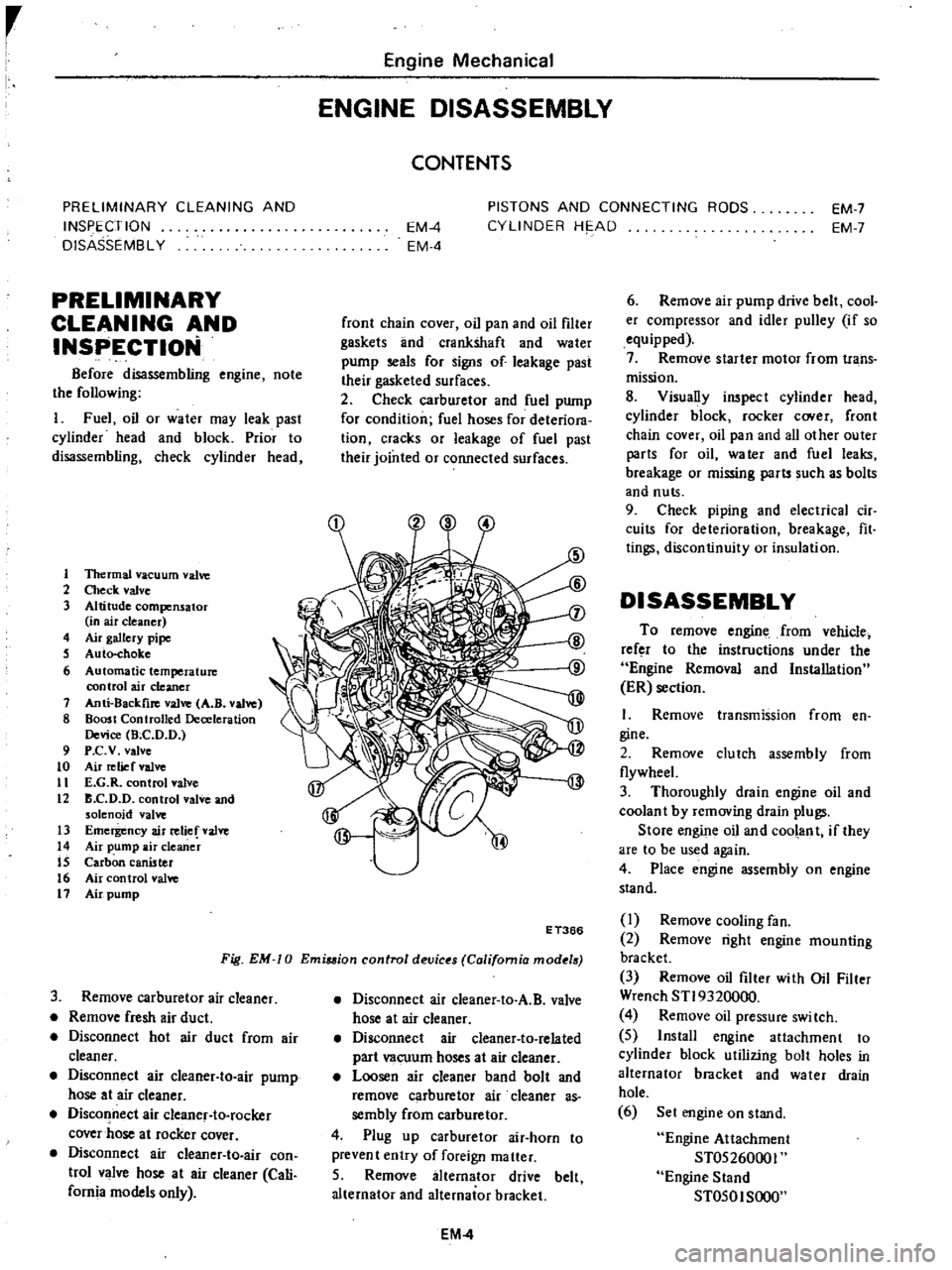
1
1ltermal
vacuum
valve
2
Check
valve
3
Altitude
compensator
in
air
cleaner
4
Air
gallery
pipe
S
Auto
choke
6
Automatic
temperature
control
air
cleaner
7
Anti
8ackfire
valve
A
B
valve
8
Boost
Controlled
Deceleration
Device
Bee
D
D
9
P
c
v
valve
to
Air
relief
valve
11
E
G
R
control
valve
12
B
C
D
D
control
valve
and
solenoid
valve
13
Emergency
air
relief
valve
14
Air
pump
air
cleaner
IS
Carbon
canister
16
Air
control
valve
11
Air
pump
Engine
Mechanical
ENGINE
DISASSEMBLY
CONTENTS
EM
4
EM
4
PISTONS
AND
CONNECTING
RODS
CYLINDER
HE
AD
EM
7
EM
7
front
chain
cover
oil
pan
and
oil
filter
gaskets
lInd
crankshaft
and
water
pump
seals
for
signs
of
leakage
past
their
gasketed
surfaces
2
Check
carburetor
and
fuel
pump
for
condition
fuel
hoses
for
deteriora
tion
cracks
or
leakage
of
fuel
past
their
jointed
or
connected
surfaces
Fig
EM
0
Emiuion
control
devic
s
California
mod
18
E
T366
3
Remove
carburetor
air
cleaner
Remove
fresh
air
duct
Disconnect
hot
air
duct
from
air
cleaner
Disconnect
air
cleaner
to
air
pump
hose
at
air
cleaner
Disconnect
air
cleanef
to
rocker
cover
hose
at
rocker
cover
Disconnect
air
cIeaner
to
air
con
trol
valve
hose
at
air
cleaner
Cali
fornia
models
only
Disconnect
air
cleaner
to
A
B
valve
hose
at
air
cleaner
Disconnect
air
cleaner
to
related
part
vacuum
hoses
at
air
cleaner
Loosen
air
cleaner
band
bolt
and
remove
carburetor
air
cleaner
as
sembly
from
carburetor
4
Plug
up
carburetor
air
horn
to
prevent
entry
of
foreign
matter
5
Remove
alternator
drive
belt
alternator
and
alternator
bracket
EM
4
6
Remove
air
pump
drive
belt
cool
er
compressor
and
idler
pulley
if
so
equipped
7
Remove
starter
motor
from
trans
mission
8
Visually
inspect
cylinder
head
cylinder
block
rocker
C
Ner
front
chain
cover
oil
pan
and
all
other
outer
parts
for
oil
water
and
fuel
leaks
breakage
or
missing
parts
such
as
bolts
and
nuts
9
Check
piping
and
electrical
cir
cuits
for
deterioration
breakage
fit
tings
discontinuity
or
insulation
DISASSEMBLY
To
remove
engine
from
vehicle
refer
to
the
instructions
under
the
Engine
Removal
and
Installation
ER
section
I
Remove
transmission
from
en
gine
2
Remove
clutch
assembly
from
flywheeL
3
Thoroughly
drain
engine
oil
and
coolan
t
by
removing
drain
plugs
Store
engine
oil
and
coolant
if
they
are
to
be
used
again
4
Place
engine
assembly
on
engine
stand
I
Remove
cooling
fan
2
Remove
right
engine
mounting
bracket
3
Remove
oil
filter
with
Oil
Filter
Wrench
STI9320000
4
Remove
oil
pressure
swi
tch
5
Install
engine
attachment
to
cylinder
block
utilizing
bolt
holes
in
alternator
bracket
and
water
drain
hole
6
Set
engine
on
stand
Engine
Attachment
ST05260001
Engine
Stand
ST050I
SOOO
Page 71 of 537
30
Install
heatshieid
plate
on
mani
fold
assembly
31
Install
air
gallery
pipe
on
ex
haust
manifold
32
Install
manifold
gasket
and
manifold
assembly
on
cylinder
head
Tightening
torque
1
2to
1
6kg
m
8
7
to
11
6
ft
lb
33
Install
blow
by
gas
pipe
on
cyl
inder
block
and
tighten
with
rear
engine
slinger
34
Install
thermostat
housing
gas
ket
thermostat
housing
and
thermo
stat
35
Install
thermal
vacuum
valve
on
thermostat
housing
Before
installing
apply
a
liquid
packing
slightly
to
the
threads
36
Install
FJ
C
D
bracket
on
cylin
der
head
37
Install
E
G
R
passage
and
E
G
R
valve
on
intake
manifold
38
Connect
E
G
R
tube
to
E
G
R
tube
and
exhaust
manifold
39
Install
check
valve
on
air
gallery
pipe
40
Install
air
cleaner
bracket
on
intake
manifold
41
Install
air
control
valve
on
air
cleaner
bracket
California
models
42
Install
vacuum
and
fuel
tubes
combined
on
cylinder
head
43
Install
distributor
assembly
44
Install
heatshield
plate
joint
seat
and
carburetor
Carbure10r
tightening
torque
0
5
to
1
0
kg
m
3
6
to
7
2
ft
lb
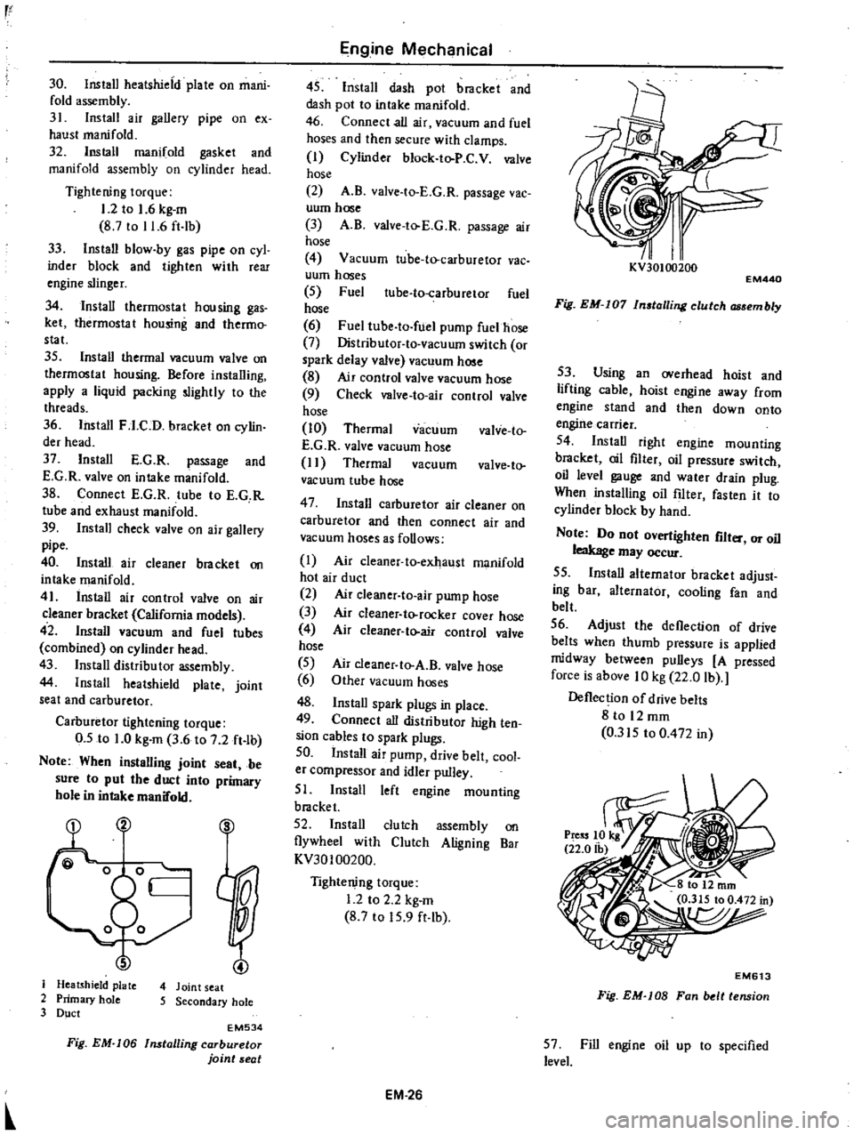
Note
When
instalUng
joint
seat
be
sure
to
put
the
duct
into
primary
hole
in
intake
manifold
S
J
Heatshield
plate
4
Joint
seat
2
Primary
hole
5
Secondary
hole
3
Duct
EM534
Fig
EM
I06
Installing
carburetor
joint
seat
Engine
Mechanical
45
Install
dash
pot
bracket
and
dash
pot
to
intake
manifold
46
Connect
all
air
vacuum
and
fuel
hoses
and
then
secure
with
clamps
I
Cylinder
block
to
P
C
V
valve
hose
2
A
B
valve
to
E
G
R
passage
vac
uum
hose
3
A
B
valve
to
E
G
R
passage
air
hose
4
Vacuum
tube
to
carburetor
vac
uum
hoses
5
Fuel
ube
to
carburetor
fuel
hose
6
Fuel
tube
to
fuel
pump
fuelhose
7
Distributor
to
vacuum
switch
or
spark
delay
valve
vacuum
hose
8
Air
control
valve
vacuum
hose
9
Check
valve
to
air
control
valve
hose
10
Thermal
vacuum
valve
to
E
G
R
valve
vacuum
hose
I
I
Thermal
vacuum
valve
to
vacuum
tube
hose
47
Install
carburetor
air
cleaner
on
carburetor
and
then
connect
air
and
vacuum
hoses
as
follows
I
Air
cleaner
to
exhaust
manifold
hot
air
duct
2
Air
c1eaner
to
air
pump
hose
3
Air
cleaner
to
rocker
cover
hose
4
Air
cleaner
to
air
control
valve
hose
5
6
48
Install
spark
plugs
in
place
49
Connect
all
distributor
high
ten
sion
cables
to
spark
plugs
50
Install
air
pump
drive
belt
cool
er
compressor
and
idler
pulley
51
Install
left
engine
mounting
bracket
52
Install
clutch
assembly
on
flywheel
with
Clutch
Aligning
Bar
KV30100200
Air
cleaner
to
A
B
valve
hose
Other
vacuum
hoses
Tightening
torque
1
2
to
2
2
kg
m
8
7
to
15
9
ft
lb
EM
26
I
I
KV30100200
EM440
Fig
EM
I07
In
talling
clutch
embly
53
Using
an
overhead
hoist
and
lifting
cable
hoist
engine
away
from
engine
stand
and
then
down
onto
engine
carrier
54
Install
right
engine
mounting
bracket
oil
filter
oil
pressure
switch
oil
level
gauge
and
water
drain
plug
When
installing
oil
filter
fasten
it
to
cylinder
block
by
hand
Note
Do
not
overtighten
flit
or
oil
leakage
may
occur
55
Install
alternator
bracket
adjust
ing
bar
alternator
cooling
fan
and
belt
56
Adjust
the
deflection
of
drive
belts
when
thumb
pressure
is
applied
midway
between
pulleys
A
pressed
force
is
above
10
kg
22
0
lb
Deflection
of
drive
belts
8
to
12
mm
0
315
to
0
472
in
EM613
Fig
EM
lOB
Fan
belt
tension
57
Fill
engine
oil
up
to
specified
level
Page 101 of 537

TEMPERATURE
SENSOR
The
temperature
sensor
is
attached
to
the
inside
of
the
air
cleaner
The
bimetal
built
in
the
sensor
detects
the
under
hood
air
temperature
and
opens
or
closes
the
vacuum
passage
in
the
sensor
The
construction
of
the
tempera
ture
sensor
is
shown
in
the
following
CD
V
00
@
I
I
@
j
I
I
1
Protector
cover
Screw
Adjusting
frame
Air
temperature
bi
metal
Rivet
Valve
seat
frame
Lower
frame
Air
bleed
valve
Gasket
Fig
EF
6
Temperature
senior
EF206
VACUUM
MOTOR
AND
AIR
CONTROL
VALVE
The
vacuum
pressure
which
varies
with
opening
of
the
carburetor
throt
tle
acts
upon
the
vacuum
motor
dia
phragm
The
valve
shaft
attached
to
the
diaphragm
is
then
moved
up
or
down
in
response
to
the
vacuum
on
the
diaphragm
This
movement
of
the
valve
shaft
actuates
the
air
control
valve
to
control
the
temperature
of
the
air
to
be
introduced
into
the
air
cleaner
pr
to
I
1
Valve
spring
00
2
Diaphragm
@
3
Retainer
E
F
207
4
Valve
shaft
Fig
EF
7
Vacuum
motor
REMOVAL
AND
INSTALLATION
TEMPERATURE
SENSOR
Removal
Using
pliers
flatten
clip
con
Engine
Fuel
neeting
vacuum
hose
to
sensor
vacuum
tube
I
Pipe
2
Calch
3
Fixed
with
adhesive
4
Hose
5
Tab
6
Clip
7
Gasket
EC019
Fig
EF
B
Removal
of
semor
2
Disconnect
hose
from
sensor
3
Take
off
clip
from
sensor
vacuum
tube
and
dismount
sensor
body
from
air
cleaner
Note
The
gasket
between
sensor
and
air
cleaner
is
bonded
to
the
air
cleaner
side
and
should
not
be
removed
Inatallatlon
Mount
sensor
on
the
specified
position
For
mounting
position
of
sensor
see
the
following
EF717
Fig
EF
9
lalling
se
or
2
Insert
clip
into
vacuum
tube
of
sensor
After
installing
each
vacuum
hose
secure
hose
with
the
clip
Note
Be
sure
to
install
vacuum
hose
correctly
Correct
position
is
R
H
side
to
Nissan
mark
at
the
top
face
of
sensor
for
intake
manifold
L
H
side
for
vacuum
motor
VACUUM
MOTOR
1
Remove
screws
securing
vacuum
motor
to
air
cleaner
2
Disconnect
valve
shaft
attached
to
vacuum
motor
diapluagm
from
air
control
valve
and
remove
cacuum
motor
assembly
from
air
cleaner
3
To
install
reverse
the
removal
procedure
FRESH
AIR
DUCT
I
Disconnect
fresh
air
duct
at
air
cleaner
2
Fresh
air
duct
is
provided
with
projections
on
its
air
inlet
side
end
Hold
fresh
air
duct
with
a
hand
and
carefully
pull
out
from
radiator
core
support
while
turning
it
in
either
direction
3
To
install
reverse
the
removal
procedure
Be
sure
to
insert
projec
lions
of
fresh
air
duct
securely
into
mounting
hole
in
radiator
core
sup
port
EF518
EF
5
Fresh
air
duct
Air
cleaner
Duct
mounting
hole
Radiator
Radiator
core
support
Fig
EF
I0
Removal
of
fresh
air
duct
Page 105 of 537
DESCRIPTION
FUEL
PUMP
TESTING
STATIC
PRESSURE
TEST
CAPACITY
TEST
DESCRIPTION
The
fuel
pump
transfers
fuel
from
the
tank
to
the
carburetor
in
sufficient
quantity
to
meet
the
engine
require
ments
at
any
speed
or
load
The
fuel
pump
is
a
pulsating
type
designed
for
easy
maintenance
It
con
sists
of
a
body
a
rocker
arm
assembly
a
fuel
diaphragm
a
fuel
diaphragm
spring
seal
inlet
and
outlet
valves
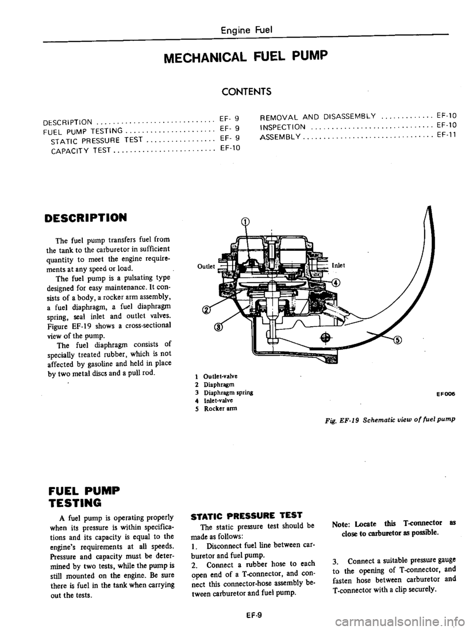
Figure
EF
19
shows
a
cross
sectional
view
of
the
pump
The
fuel
diaphragm
consists
of
specially
treated
rubber
which
is
not
affected
by
gasoline
and
held
in
place
by
two
metal
discs
and
a
pull
rod
FUEL
PUMP
TESTING
A
fuel
pump
is
operating
properly
when
its
pressure
is
within
specifica
tions
and
its
capacity
is
equal
to
the
engine
s
requirements
at
all
speeds
Pressure
and
capacity
must
be
deter
mined
by
two
tests
while
the
pump
is
still
mounted
on
the
engine
Be
sure
there
is
fuel
in
the
tank
when
carrying
out
the
tests
Engine
Fuel
MECHANICAL
FUEL
PUMP
CONTENTS
EF
9
EF
9
EF
9
EF
10
REMOVAL
AND
DISASSEMBLY
INSPECTION
ASSEMBL
Y
EF
10
EF
10
EF
11
1
1
Outlet
valve
2
Diaphragm
3
Diaphragm
spring
4
Inlet
valve
S
Rocker
ann
EF006
Fig
EF
19
Schematic
view
of
fuel
pump
STATIC
PRESSURE
TEST
The
static
pressure
test
should
be
made
as
follows
I
Disconnect
fuel
line
between
car
buretor
and
fuel
pump
2
Connect
a
rubber
hose
to
each
open
end
of
a
T
connector
and
con
nect
this
connector
hose
assembly
be
tween
carburetor
and
fuel
pump
Note
Locate
this
T
connector
as
close
to
carburetor
as
possible
3
Connect
a
suitable
pressure
gauge
to
the
opening
of
T
connector
and
fasten
hose
between
carburetor
and
T
connector
with
a
clip
securely
EF
9