lights DATSUN PICK-UP 1977 Service Manual
[x] Cancel search | Manufacturer: DATSUN, Model Year: 1977, Model line: PICK-UP, Model: DATSUN PICK-UP 1977Pages: 537, PDF Size: 35.48 MB
Page 32 of 537
r
CHECKING
B
C
D
D
SOLENOID
VALVE
I
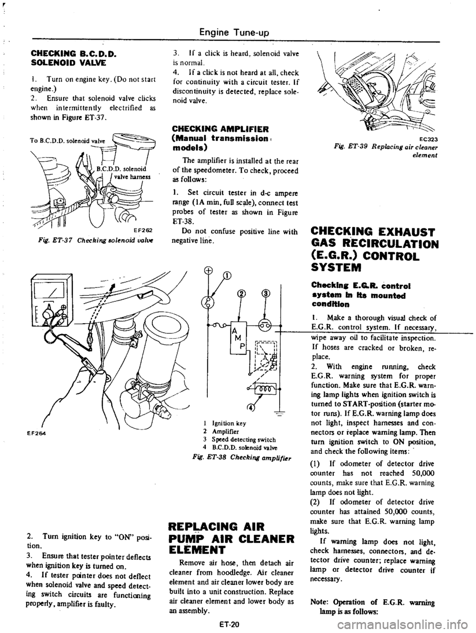
Turn
on
engine
key
Do
not
start
engine
2
Ensure
that
solenoid
valve
clicks
when
intermittently
electrified
as
shown
in
Figure
ET
37
Fig
ET
37
Checking
solenoid
uolV
l
I
l
EF264
2
Turn
ignition
key
to
ON
posi
tion
3
Ensure
that
tester
pointer
deflects
when
ignition
key
is
turned
on
4
If
tester
panter
does
not
deflect
when
solenoid
valve
and
speed
detect
ing
switch
circuits
are
functioning
properly
amplifier
is
faulty
Engine
Tune
up
3
If
a
click
is
heard
solenoid
valve
is
normal
4
If
a
click
is
not
heard
at
all
check
for
continuity
with
a
circuit
tester
If
discontinuity
is
detected
replace
sole
naid
valve
CHECKING
AMPLIFIER
Manual
transmission
models
The
amplifier
is
installed
at
the
rear
of
the
speedometer
To
check
proceed
as
follows
1
Set
circuit
tester
in
d
c
ampere
range
IA
min
full
scale
connect
test
probes
of
tester
as
shown
in
Figure
ET
38
Do
not
confuse
positive
line
with
negative
line
M
p
1
II
L
o
A
I
of
j
t
J
f
T
1
Ignition
key
2
Amplifier
3
Speed
detecting
switch
4
B
C
D
D
solenoid
valve
Fig
ET
38
Checking
amplifiu
REPLACING
AIR
PUMP
AIR
CLEANER
ELEMENT
Remove
air
hose
then
detach
air
cleaner
from
hoodledge
Air
cleaner
element
and
air
cleaner
lower
body
are
built
into
a
unit
construction
Replace
air
cleaner
element
and
lower
body
as
an
assembly
ET
20
EC323
Fig
ET
39
Repl4cing
air
cleaner
element
CHECKING
EXHAUST
GAS
RECIRCULATION
E
G
R
CONTROL
SYSTEM
Checkln
E
G
R
control
system
In
Ita
mounted
condition
I
M
ake
a
thorough
visual
check
of
E
G
R
control
system
If
necessary
wipe
away
oil
to
facilitate
inspection
If
hoses
are
cracked
or
broken
fe
place
2
With
engine
running
check
E
G
R
warning
system
for
proper
function
Make
sure
that
E
G
R
warn
ing
lamp
light
when
ignition
switch
is
turned
to
START
position
starter
mo
tor
runs
If
E
G
R
warning
lamp
does
not
light
inspect
harnesses
and
con
nectors
or
replace
warning
lamp
Then
turn
ignition
switch
to
ON
position
and
check
the
following
items
I
If
odometer
of
detector
drive
counter
has
not
reached
50
000
counts
make
sure
that
E
G
R
warning
lamp
does
not
light
2
If
odometer
of
detector
drive
counter
has
attained
50
000
counts
make
sure
that
E
G
R
warning
lamp
lights
If
warning
lamp
does
not
light
check
harnesses
connector
and
de
tector
drive
counter
replace
warning
lamp
or
detector
drive
counter
if
necessary
Note
Operation
of
E
G
R
warning
lamp
is
as
follows
Page 35 of 537
3
If
there
is
a
leak
remove
top
cover
from
purge
contiol
valve
and
check
for
dislocated
or
cmcked
dia
phragm
If
necessary
replace
dia
phmgm
kit
which
is
made
up
of
a
retainer
diaphragm
and
spring
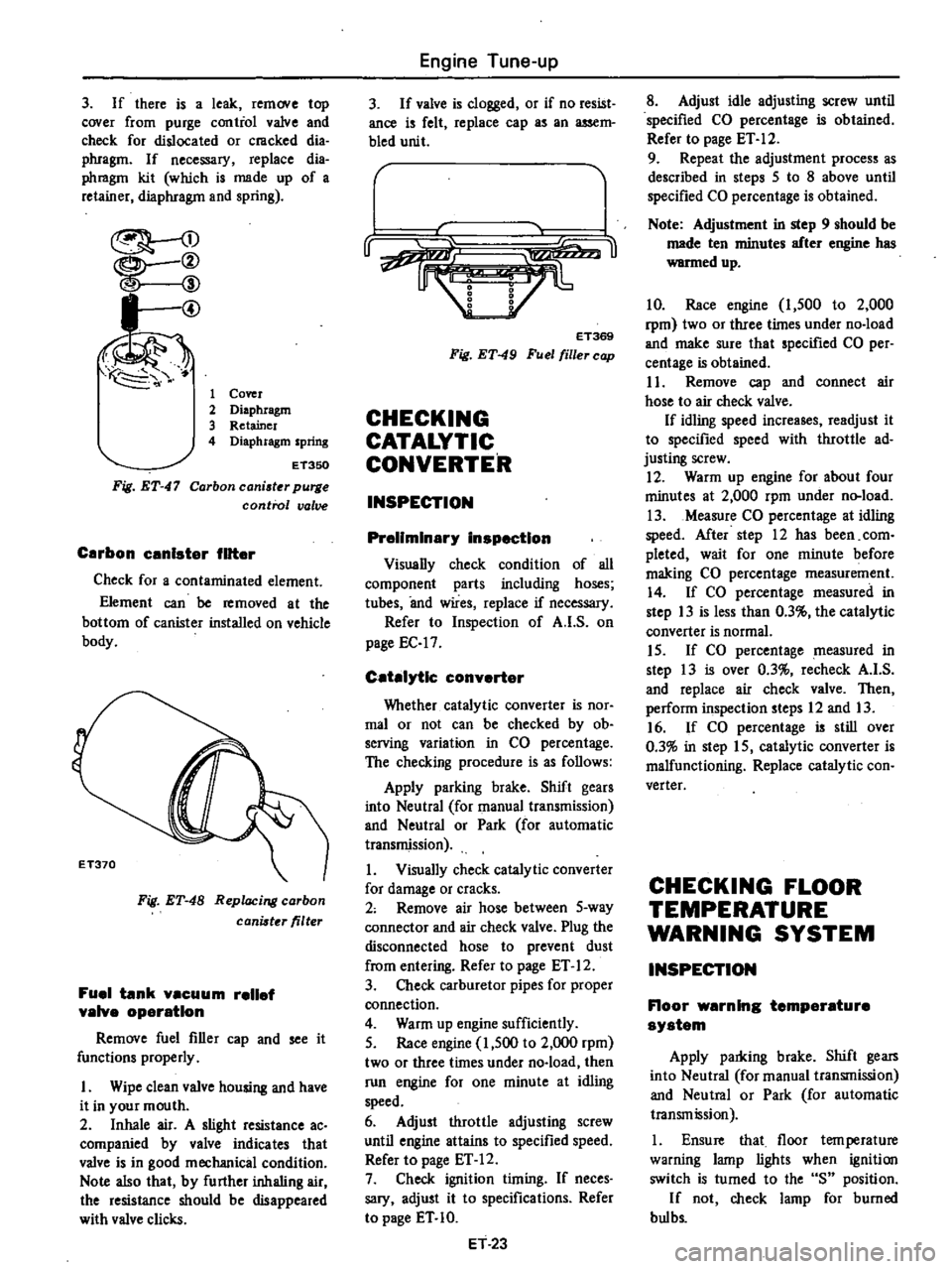
I
@
1
Cover
2
Diaphragm
3
Retainer
4
Diaphragm
spring
Fig
ET
47
ET350
Carbon
caniater
purge
control
valve
Carbon
unlster
filter
Check
for
a
contaminated
element
Element
can
be
removed
at
the
bottom
of
canister
installed
on
vehicle
body
Fig
ET
48
Replacing
carbon
canister
filter
Fuel
tank
vacuum
relief
valve
operation
Remove
fuel
filler
cap
and
see
it
functions
properly
I
Wipe
clean
valve
housing
and
have
it
in
your
mouth
2
Inhale
air
A
slight
resistance
ac
companied
by
valve
indicates
that
valve
is
in
good
mechanical
condition
Note
also
that
by
further
inhaling
air
the
resistance
should
be
disappeared
with
valve
clicks
Engine
Tune
up
3
If
valve
is
clogged
or
if
no
resist
ance
is
felt
replace
cap
as
an
assem
bled
unit
r
u
ET369
Fig
ET
49
Fuel
filler
cap
CHECKING
CATALYTIC
CONVERTER
INSPECTION
Preliminary
inspection
Visually
check
condition
of
all
component
parts
including
hoses
tubes
and
wires
replace
if
necessary
Refer
to
Inspection
of
A
I
S
on
page
EC
17
Catalytic
converter
Whether
catalytic
converter
is
nOf
mal
or
not
can
be
checked
by
ob
serving
variation
in
CO
percentage
The
checking
procedure
is
as
follows
Apply
parking
brake
Shift
gears
into
Neutral
for
manual
transmission
and
Neutral
or
Park
for
automatic
transmission
1
Visually
check
catalytic
converter
for
damage
or
cracks
2
Remove
air
hose
between
5
way
connector
and
air
check
valve
Plug
the
disconnected
hose
to
prevent
dust
from
entering
Refer
to
page
ET
12
3
Check
carburetor
pipes
for
proper
connection
4
Warm
up
engine
sufficiently
5
Race
engine
1
500
to
2
000
rpm
two
or
three
times
under
no
load
then
run
engine
for
one
minute
at
idling
speed
6
Adjust
throttle
adjusting
screw
until
engine
attains
to
specified
speed
Refer
to
page
ET
12
7
Check
ignition
timing
If
neces
sary
adjust
it
to
specifications
Refer
to
page
ET
10
ET
23
8
Adjust
idle
adjusting
screw
until
specified
CO
percentage
is
obtained
Refer
to
page
ET
12
9
Repeat
the
adjustment
process
as
described
in
steps
5
to
8
above
until
specified
CO
percentage
is
obtained
Note
Adjustment
in
step
9
should
be
made
ten
minutes
after
engine
has
warmed
up
10
Race
engine
1
500
to
2
000
rpm
two
or
three
times
under
no
load
and
make
sure
that
specified
CO
per
centage
is
obtained
I
1
Remove
cap
and
connect
air
hose
to
air
check
valve
If
idling
speed
increases
readjust
it
to
specified
speed
with
throttle
ad
justing
screw
12
Warm
up
engine
for
about
four
minutes
at
2
000
rpm
under
n
load
13
Measure
CO
percentage
at
idling
speed
After
step
12
has
been
com
pleted
wait
for
one
minute
before
making
CO
percentage
measurement
14
If
CO
percentage
measured
in
step
13
is
less
than
0
3
the
catalylic
converter
is
normal
15
If
CO
percentage
measured
in
step
13
is
over
0
3
recheck
A
I
S
and
replace
air
check
valve
Then
perform
inspection
steps
12
and
13
16
If
CO
percentage
is
still
over
0
3
in
step
15
catalytic
converter
is
malfunctioning
Replace
catalytic
con
verter
CHECKING
FLOOR
TEMPERATURE
WARNING
SYSTEM
INSPECTION
Floor
warning
temperature
system
Apply
parldng
brake
Shift
gears
into
Neutral
for
manual
transmission
and
Neutral
or
Park
for
automatic
transmission
1
Ensure
that
floor
tern
perature
warning
lamp
lights
when
ignition
switch
is
turned
to
the
S
position
If
not
check
lamp
for
burned
bul
bs
Page 157 of 537
4
E
G
R
warning
system
EC251
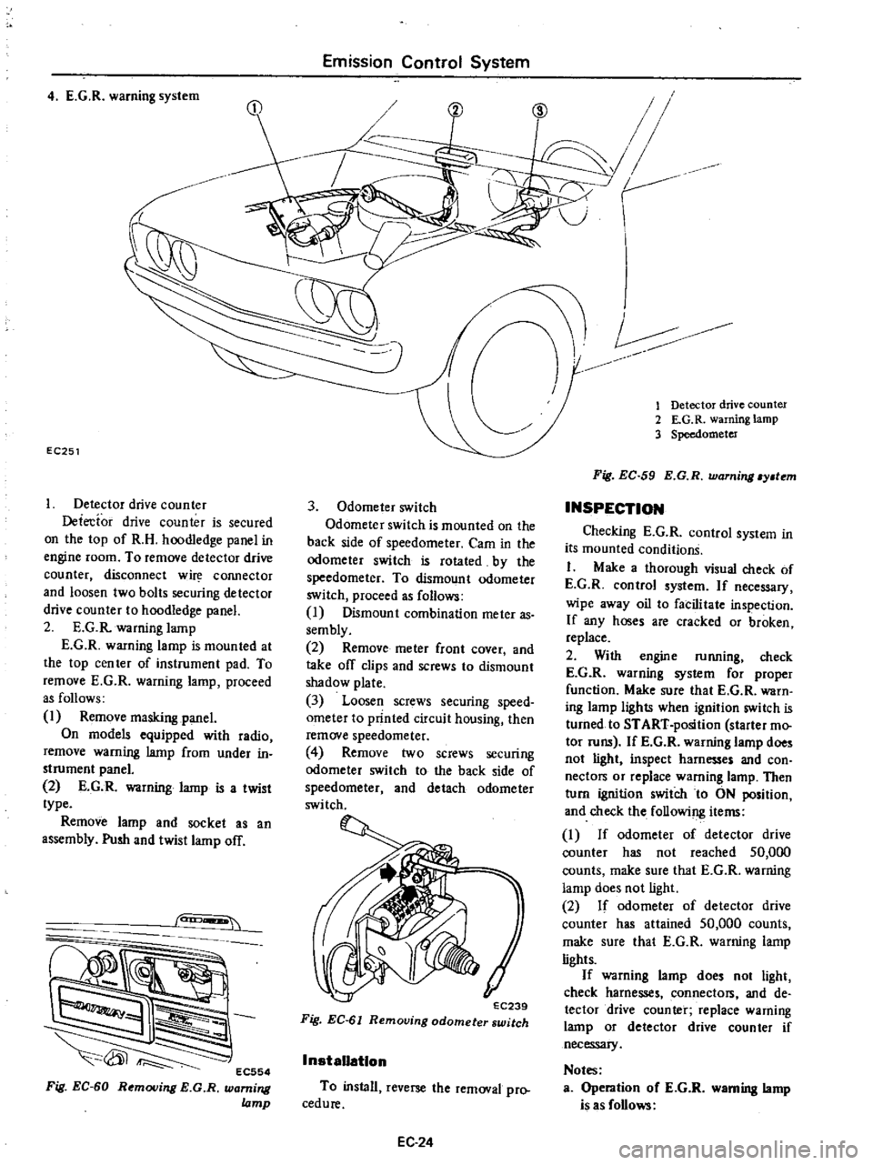
Detector
drive
counter
Detecfor
drive
counter
is
secured
on
the
top
of
R
H
hoodledge
panel
in
engine
room
To
remove
detector
drive
counter
disconnect
w
COJUlector
and
loosen
two
bolts
securing
detector
drive
counter
to
hoodledge
panel
2
E
G
R
warning
lamp
E
G
R
warning
lamp
is
mounted
at
the
top
cen
ter
of
instrument
pad
To
remove
E
G
R
warning
lamp
proceed
as
follows
1
Remove
masking
panel
On
models
equipped
with
radio
remove
warning
lamp
from
under
in
strument
panel
2
E
G
R
warning
lamp
is
a
twist
type
Remove
lamp
and
socket
as
an
assembly
Push
and
twist
lamp
off
can
EC554
Fig
EC
60
Removing
E
G
R
warning
lamp
Emission
Control
System
3
Odometer
switch
Odometer
switch
is
mounted
on
the
back
side
of
speedometer
Cam
in
the
odometer
switch
is
rotated
by
the
speedometer
To
dismount
odometer
switch
proceed
as
follows
I
Dismount
combination
meter
as
sembly
2
Remove
meter
front
cover
and
take
off
clips
and
screws
to
dismount
shadow
plate
3
Loosen
screws
securing
speed
ometer
to
printed
circuit
housing
then
remove
speedometer
4
Remove
two
screws
securing
odomete
switch
to
the
back
side
of
speedometer
and
detach
odometer
switch
EC239
Fig
EC
61
Removing
odometer
switch
InstaUatlon
To
install
reverse
the
removal
pro
cedure
EC24
V
r
CID
1
Detector
drive
counter
2
E
G
R
warning
lamp
3
Speedometer
Fig
EC
59
E
G
R
warning
y
tem
INSPECTION
Checking
E
G
R
control
system
in
its
mounted
conditionS
I
Make
a
thorough
visual
check
of
E
G
R
control
system
If
necessary
wipe
away
oil
to
facilitate
inspection
If
any
hoses
are
cracked
or
broken
replace
2
With
engine
running
check
E
G
R
warning
system
for
proper
function
Make
sure
that
E
G
R
warn
ing
lamp
lights
when
ignition
switch
is
turned
to
START
position
starter
mo
tor
runs
If
E
G
R
wanung
lamp
does
not
light
inspect
harnesses
and
con
nectors
or
replace
warning
lamp
Then
turn
ignition
switch
to
ON
position
and
check
the
following
items
I
If
odometer
of
detector
drive
counter
has
not
reached
50
000
counts
make
sure
that
E
G
R
warning
lamp
does
not
light
2
If
odomete
of
detector
drive
counter
has
attained
50
000
counts
make
sure
that
E
G
R
warning
lamp
lights
If
warning
lamp
does
not
light
check
harnesses
connectors
and
de
tector
drive
counter
replace
warning
lamp
or
detector
drive
counter
if
necessary
Notes
Operation
oC
E
G
R
warning
lamp
is
as
Collows
Page 162 of 537
Floor
temparature
warning
lamp
Refer
to
Figure
EC
74
for
the
loca
tion
of
this
part
L
1t
1
RAt
Fig
EC
74
Location
of
floor
temperature
warning
lamp
INSTALLATION
To
install
reverse
the
order
of
rem
ovaL
INSPECTION
Floor
warning
temperature
system
Apply
parking
brake
Shift
gears
into
Neutral
foI
manual
transmission
and
Neutral
or
Park
for
automatic
transmission
1
Ensure
that
floor
temperature
warning
lamp
lights
when
ignition
switch
is
iumed
to
the
S
position
If
not
check
lamp
for
burned
bulbs
Replace
bulb
if
bulb
is
burned
out
If
bulb
is
not
burned
trace
wire
s
back
to
ignition
switch
Repair
or
replace
if
necessary
2
Be
sure
that
floor
temperature
is
cool
below
800C
1760Fj
before
carrying
out
the
following
procedure
I
Remove
rearseat
2
Ignition
switch
is
turned
to
the
IG
position
3
Ensure
that
floor
temperature
warning
lamp
goes
out
4
Heat
surrounding
areas
of
floor
temperature
sensing
switch
with
a
proper
heater
to
ensure
that
floor
temperature
warning
lamp
glows
when
floor
is
heated
to
the
specifications
as
shown
in
the
table
below
Emission
Control
System
Temperature
sensing
switch
Contact
close
Temperature
warning
lamp
Off
Contact
open
On
Note
Avoid
heating
floor
tempera
ture
sensing
switch
directly
If
lamp
does
not
glow
check
floor
temperature
sensing
switch
connector
for
continuity
with
a
circuit
tester
If
continuity
should
exist
after
heated
surrounding
areas
of
floor
tem
perature
sensing
switch
replace
tem
perature
sensing
switch
If
con
tinuity
does
not
exist
trace
the
wiring
back
to
relay
or
check
the
following
step
3
Repair
or
replace
wire
s
if
necessary
Note
The
floor
temperature
sensing
switch
may
be
heated
through
the
floor
by
a
proper
heater
3
Turn
ignition
switch
to
the
IG
position
and
disconnect
floor
temper
ature
sensing
connector
The
lamp
should
remain
on
If
not
check
floor
temperature
relay
for
continuity
with
2
00
r
I
141
J
To
floor
temperatwe
warning
lamp
2
From
S
position
3
From
IG
position
4
From
ignition
switch
5
To
floor
temperature
sensing
switch
O
When
floor
temperature
warning
lamp
lights
Check
floor
temperature
warning
lamp
1
Open
or
shorj
circuit
in
wiring
harness
2
Check
fuel
system
with
regard
to
the
following
items
Refer
to
Inspec
lion
of
Fuel
System
EC
29
Floor
temperature
Below
1050C
221
OF
Above
1050C
221
OF
a
circuit
tester
Referring
to
the
following
floor
temperature
relay
if
relay
is
normal
trace
wire
s
back
to
ignition
switch
Repair
faulty
wiring
Floor
temperature
relay
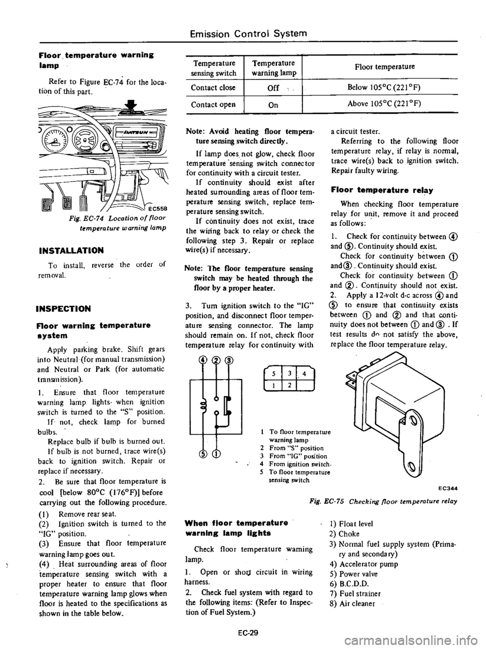
When
checking
floor
temperature
relay
for
unit
remove
it
and
proceed
as
follows
1
Check
for
continuity
between
@
and
ID
Continuity
should
exist
Check
for
continuity
between
CD
and@
Continuity
should
exist
Check
for
continuity
between
CD
and
@
Continuity
should
not
exist
2
Apply
a
12
volt
doc
across
@
and
ID
to
ensure
that
continuity
exists
between
CD
and
@
and
that
con
ti
nuity
does
not
between
CD
and
@
If
test
results
dn
not
satisfy
the
above
replace
the
floor
temperature
relay
EC344
Fig
EC
75
Checking
floor
temperature
relay
1
Float
level
2
Choke
3
Normal
fuel
supply
system
Prima
ry
and
secondary
4
Accelerator
pump
5
Power
valve
6
B
C
D
D
7
Fuel
strainer
8
Air
cleaner
Page 179 of 537
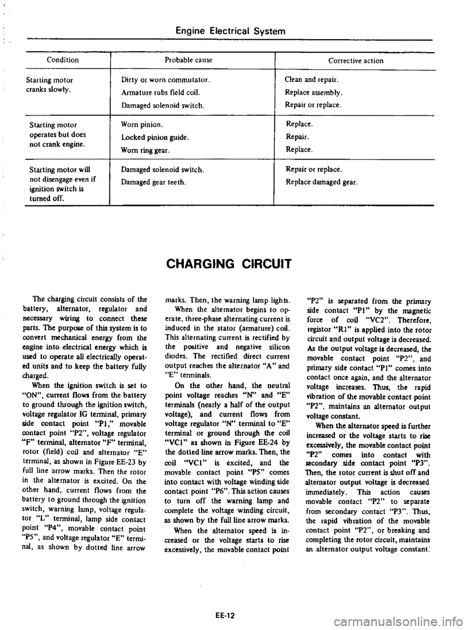
Condition
Engine
Electrical
System
Probable
cause
Starting
motor
cranks
slowly
Dirty
or
worn
commutator
Armature
rubs
field
coil
Damaged
solenoid
switch
Starting
motor
operates
but
does
not
crank
engine
Worn
pinion
Locked
pinion
guide
Worn
ring
gear
Starting
motor
will
not
disengage
even
if
ignition
switch
is
turned
off
Damaged
solenoid
switch
Damaged
gear
teeth
The
charging
circuit
consists
of
the
battery
alternator
regulator
and
necessary
wiring
to
connect
these
parts
The
purpose
of
this
system
is
to
convert
mechanical
energy
from
the
engine
into
electrical
energy
which
is
used
to
operate
all
electrically
operat
ed
units
and
to
keep
the
battery
fully
charged
When
the
ignition
switch
is
set
to
ON
current
flows
from
the
battery
to
ground
through
the
ignition
switch
voltage
regulator
IG
terminal
primary
side
contact
point
PI
movable
contact
point
P2
voltage
regulator
IF
terminal
alternator
IF
terminal
rotor
field
coil
and
alternator
E
terminal
as
shown
in
Figure
EE
23
by
full
line
arrow
marks
Then
the
rotor
in
the
alternator
is
excited
On
the
other
hand
current
flows
from
the
battery
to
ground
through
the
ignition
switch
warning
lamp
voltage
regula
tor
L
terminal
lamp
side
contact
point
P4
movable
contact
point
P5
and
voltage
regulator
E
termi
nal
as
shown
by
dotted
line
arrow
CHARGING
CIRCUIT
marks
Then
the
warning
lamp
lights
When
the
alternator
begins
to
op
erate
three
phase
alternating
current
is
induced
in
the
stator
armature
coil
This
alternating
current
is
rectified
by
the
positive
and
negative
silicon
diodes
The
rectified
direct
current
output
reaches
the
alternator
A
and
E
terminals
On
the
other
hand
the
neutral
point
voltage
reaches
N
and
E
terminals
nearly
a
half
of
the
output
voltage
and
current
flows
from
voltage
regulator
N
terminal
to
E
terminal
or
ground
through
the
coil
VCI
as
shown
in
Figure
EE
24
by
the
dotted
line
arrow
marks
Then
the
coil
VCI
is
excited
and
the
movable
contact
point
IPS
comes
into
contact
with
voltage
winding
side
contact
point
P6
This
action
causes
to
turn
off
the
warning
lamp
and
complete
the
voltage
winding
circuit
as
shown
by
the
full
line
arrow
marks
When
the
alternator
speed
is
in
creased
or
the
voltage
starts
to
rise
excessively
the
movable
contact
point
EE
12
Corrective
action
Clean
and
repair
Replace
assembly
Repair
or
replace
Replace
Repair
Replace
Repair
or
replace
Replace
damaged
gear
P2
is
separated
from
the
primary
side
contact
PI
by
the
magnetic
force
of
coil
VC2
Therefore
registor
RI
is
applied
into
the
rotor
circuit
and
output
voltage
is
decreased
AJ
the
output
voltage
is
decreased
the
movable
contact
point
P2
and
primary
side
contact
Pin
comes
into
contact
once
again
and
the
alternator
voltage
increases
Thus
the
rapid
vibration
of
the
movable
contact
point
IPl
maintains
an
alternator
output
voltage
constant
When
the
alternator
speed
is
further
increased
or
the
voltage
starts
to
rise
excessively
the
movable
contact
point
P2
comes
into
contact
with
secondllJ
side
contact
point
P3
Then
the
rotor
current
is
shut
off
and
alternator
output
voltage
is
decreased
immediately
This
action
causes
movable
contact
n
to
separate
from
secondary
contact
P3
Thus
the
rapid
vibration
of
the
movable
contact
point
P2
or
breaking
and
completing
the
rotor
circuit
maintains
an
alternator
output
voltage
constant
Page 186 of 537

Engine
Electrical
System
ALTERNATOR
TEST
Before
conducting
an
alternator
test
make
sure
th
tthe
battery
is
fully
charged
A
30
V
olt
voltmeter
and
suitable
test
probes
3re
necessary
for
the
test
Set
up
a
test
circuit
as
shown
in
Figure
EE45
and
test
auernator
in
the
manner
indica
ted
in
the
flow
chart
below
1
Disconnect
connectors
at
alternator
2
Connect
A
terminal
to
F
terminal
3
Connect
one
test
probe
from
voltmeter
positive
terminal
to
A
terminal
Connect
the
other
test
probe
to
ground
Make
sure
that
voltmeter
registers
battery
voltage
4
Turn
on
headlights
and
switch
to
High
Beam
5
Start
engine
6
Increase
engine
speed
gradually
until
it
is
approximately
1
100
rpm
and
take
the
voltmeter
reading
Measured
value
Below
12
5
Volts
Alternator
is
in
trouble
remove
and
check
it
for
condition
Measured
value
Over
12
5
Volts
Alternator
is
in
good
condition
Notes
a
Do
Dot
run
engine
at
the
speed
of
more
than
1
100
rpm
while
test
is
being
conducted
on
alternator
b
Do
not
race
engine
i
9
l
IV
I
Battery
EE052
Voltmeter
Fig
EE
45
Testing
alternator
SERVICE
DATA
AND
SPECIFICATIONS
Nominal
rating
V
A
LT138
IB
LTl35
36B
For
air
conditioner
1235
12
38
Negative
Negative
1
000
1
000
28
2
500
30
2
500
35
5
000
38
5
000
2
25
2
25
More
than
7
5
0
295
More
than
7
5
0
295
255
to
345
255
to
345
9
0
to
12
2
9
0
to
12
2
More
than
30
1
181
More
than
30
1
181
EE
19
Type
Ground
polarity
Minimum
revolution
when
generating
14V
with
no
load
rpm
Hot
output
current
Nrpm
Pulley
ratio
Brush
Length
Spring
pressure
mm
in
gr
oz
Slip
ring
outer
diameter
mm
in
Page 265 of 537
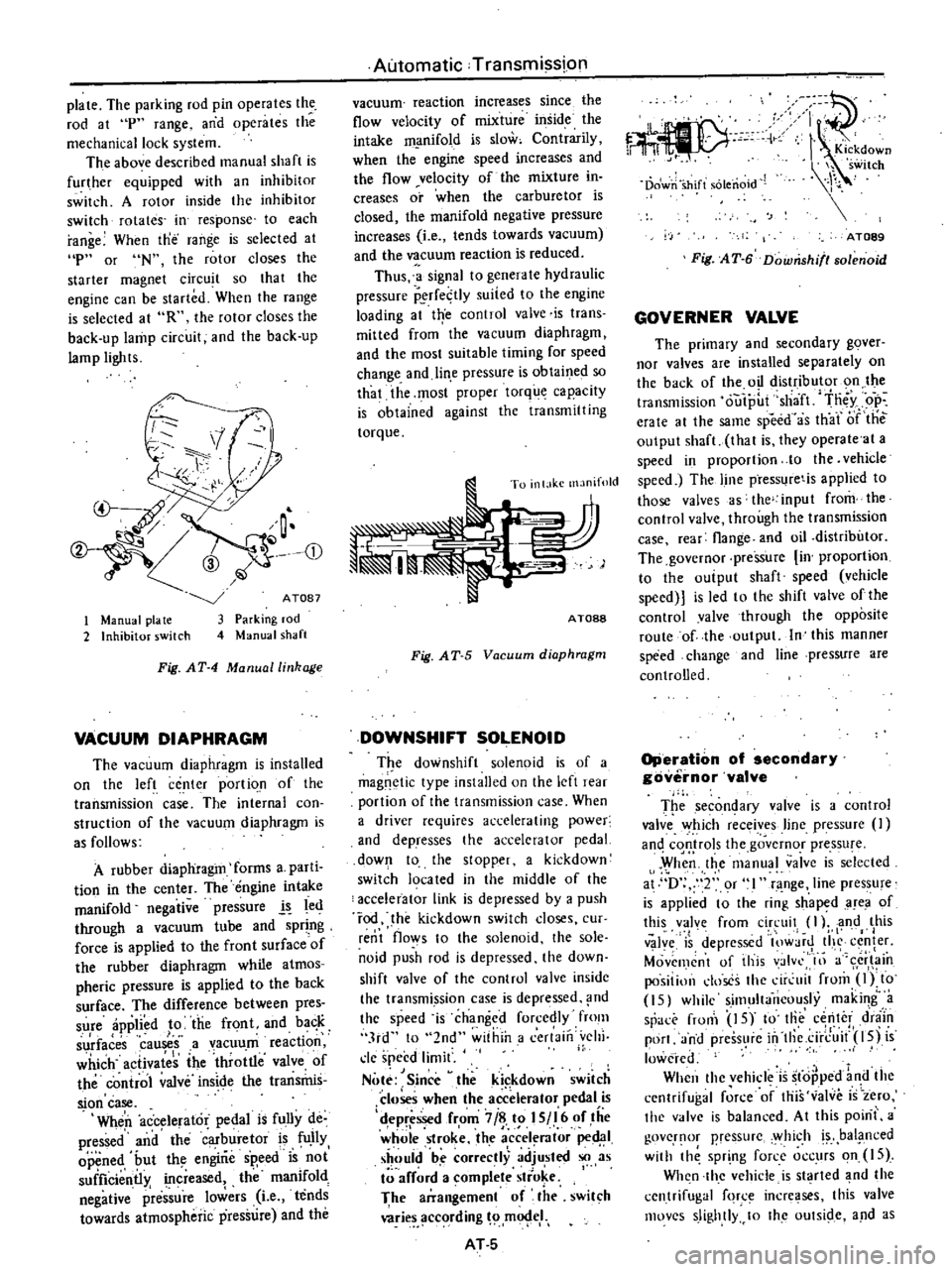
plate
The
parking
rod
pin
operates
the
rod
at
p
range
and
operates
the
mechanical
lock
system
The
above
described
manual
shaft
is
further
equipped
with
an
inhibitor
switch
A
rotor
inside
the
inhibitor
switch
rotates
in
response
to
each
range
When
tne
range
is
selected
at
p
or
N
the
rotor
closes
the
starter
magnet
circuit
so
that
the
engine
can
be
started
When
the
range
is
selected
at
R
the
rolor
closes
the
back
up
lamp
circuit
and
the
back
up
lamp
lights
CD
1
Manual
pia
te
2
Inhibitor
switch
ATOB7
Parking
rod
Manual
shaft
Fig
AT
4
Manual
linkage
VACUUM
DIAPHRAGM
The
vacuum
diaphragm
is
installed
on
the
left
center
portio
n
of
the
transmission
case
The
internal
con
struction
of
the
vacuum
diaphragm
is
as
follows
A
rubber
diaphragm
forms
a
parti
tion
in
the
center
The
engine
intake
manifold
negative
pressure
l
led
through
a
vacuum
tube
and
spring
force
is
applied
to
the
front
surfaceof
the
rubber
diaphragm
while
atmos
pheric
pressure
is
applied
to
the
back
surface
The
difference
between
pres
sure
applied
to
the
front
and
ba
K
I
surfaces
causes
a
vacuum
reactIOn
which
activates
the
throttle
valve
of
the
control
valve
inside
the
transrhis
sion
case
Wheri
accelerator
pedal
is
fully
de
pressed
and
the
buretor
is
fU
IIy
opened
but
th
engirie
sp
eed
is
not
suificientl
increased
the
manifold
negative
plre
sure
lowers
Le
tends
towards
atmospheric
pressure
and
the
Automatic
Transmission
vacuum
reaction
increases
since
the
flow
velocity
of
mixture
inside
the
intake
m
mifold
is
slow
Contrarily
when
the
engine
speed
increases
and
the
flow
velocity
of
the
mixture
in
creases
or
when
the
carburetor
is
closed
the
manifold
negative
pressure
increases
Le
tends
towards
vacuum
and
the
vacuum
reaction
is
reduced
Thus
a
signal
to
genera
Ie
hydraulic
pressure
P
rfe
tly
suited
to
the
engine
loading
at
trye
control
valve
is
trans
mitted
from
the
vacuum
diaphragm
and
the
most
suitable
timing
for
speed
change
and
lin
e
pressure
is
obtaine
so
that
the
most
proper
torque
capacity
is
obtained
against
the
transmitting
torque
To
inl
lkc
manifold
AT088
Fig
AT
5
Vacuum
diaphragm
DOWNSHIFT
SOLENOID
T
e
downshift
solenoid
is
of
a
magnetic
type
installed
on
the
left
re
r
portion
of
the
transmission
case
When
a
driver
requires
accelerating
power
and
dePresses
the
accelerator
pedal
down
to
the
stopper
a
kickdown
switch
19ca
ted
in
the
middle
of
the
accelerator
link
is
depressed
by
a
push
rod
he
kickdown
switch
doses
cur
rent
flows
to
the
solenoid
the
sole
noid
push
rod
is
depressed
the
down
shift
valve
of
the
control
valvc
insidc
the
transmi
ssion
case
is
depressed
nd
the
speed
is
changed
forcedly
fmm
3rd
to
2nd
within
a
cerlaill
vehi
cle
speed
limit
Note
Since
theki
kdown
switch
closes
when
the
accelerator
pedal
is
d
epr
ssed
from
7
i
t
I
S
I
6
of
tiie
whole
stroke
the
a
ccel
rator
ped
1
should
be
correctly
adjusted
so
as
arf
rd
a
omplete
stro
e
I
The
arrangement
of
the
swit
h
wries
ccording
m
eI
AT
S
c
C
r
11
I
Kickdown
h
switch
Dowri
shift
solenoid
AT089
Fig
AT
6
Downshifl80lenoid
GOVERNER
VALVE
The
primary
and
secondary
gover
nor
valves
are
installed
separately
on
the
back
of
the
oil
distributor
on
the
transmission
outp
t
sha
ft
tn
y
op
erate
al
the
same
speed
as
th
ar
iJf
tile
output
shaft
thai
is
they
operate
at
a
speed
in
proportion
10
the
vehicle
speed
The
line
press
retis
applied
to
those
valves
s
the
input
from
the
control
valve
through
the
transmission
case
rear
flange
and
oil
distributor
The
governor
pressure
in
proportion
to
the
ouiput
shaft
speed
vehicle
speed
is
led
to
the
shift
valve
ofthe
control
valve
through
the
opposite
route
of
the
output
In
this
manner
speed
change
and
line
pressure
are
controlled
Operation
of
secondary
governor
valve
T
e
secon
ary
valve
is
a
contro
valve
Y
hich
receives
line
pressure
an
cqQ
rols
the
governor
pressu
e
When
the
manual
valve
is
selected
at
D
2
or
l
range
line
pressure
is
applied
t
the
ri
g
sh
aped
area
of
this
valve
from
circuit
I
l
and
this
I
v
Jy
is
depressed
lOW
jr
tI
c
fer
Movemcnt
of
this
valvl
III
a
cr
in
positillll
doses
the
dr
uit
from
Olto
15
while
simultaneously
making
a
sr
rronl
IS
to
Iii
center
d
niin
port
and
press
re
in
tllc
ci
rJ
it
l5j
is
lowered
When
thc
vehicle
is
stopped
1
d
the
cenlrifugal
force
of
this
valve
is
zero
the
v
lve
is
balanced
At
this
poini
a
govcr
lOr
pressurc
y
hich
bal
i1
nced
with
th
spr
ng
force
occurs
on
IS
Wh
n
thc
vehicle
is
st
rted
nd
the
centrifugal
fqr
incre
ses
this
valve
movcs
slightly
10
Ihc
oUlSide
and
as
Page 313 of 537
In
these
cases
the
transmission
must
be
repaired
Notes
a
In
checking
oil
level
use
special
paper
cloth
to
handle
the
level
gauge
and
be
careful
not
to
let
the
scraps
of
paper
and
cloth
stick
to
the
gauge
b
Insert
the
gauge
fully
and
take
it
out
quickly
before
splashing
oil
adheres
to
the
gauge
Then
observe
the
level
c
Use
automatic
transmission
fluid
having
DEXRON
identifications
only
in
the
3N71B
automatic
trans
mission
d
Pay
attention
because
the
oil
to
be
used
differs
from
that
used
in
the
Nissan
Full
Automatic
TranSJTIis
sion
3N71A
Never
mix
the
oils
INSPECTION
AND
REPAIR
OF
OIL
LEAKAGE
When
oil
leakage
takes
place
the
portion
near
the
leakage
is
covered
with
oil
presenting
difficulty
in
detecting
the
spot
Therefore
the
places
where
oil
seals
and
gaskets
are
equipped
are
enumerated
below
11
Converter
housing
Rubber
ring
of
oil
pump
housing
Oil
seal
of
oil
pump
housing
Oil
seal
of
engine
crankshaft
Bolts
of
converter
housing
to
case
2
Trarismission
and
rear
extension
Junction
of
transm
ss
ion
and
rear
extension
J
Oil
cooler
tube
connectors
Oil
pan
Oil
pressure
inspection
holes
Refer
to
Figure
AT
il2
Mounting
portion
of
vacuum
dia
phragm
and
downshift
solenoid
Breather
and
oil
charging
pipe
Speedometer
pinion
sleeve
Oil
se
l
of
rear
extension
To
exactly
locate
the
place
of
oil
leaka
le
proceed
as
follows
Place
the
vehicle
in
a
pit
and
by
sampling
the
leaked
oil
determine
if
it
is
the
torque
converter
oil
The
torque
converter
oil
has
a
color
like
r
d
wine
So
it
is
easily
distinguished
from
engine
oil
or
gear
oil
Automatic
rransmission
Wipe
off
the
leaking
oil
and
dust
and
deiecl
the
spol
of
oil
eakage
l
se
nonflammable
organic
solve
t
s
ch
as
carbon
tetrachloride
for
wiping
Raise
the
oil
tcmperalure
by
op
erating
the
engine
and
shift
the
lever
to
D
to
increase
the
oil
pressure
The
spot
of
oil
lcakage
will
then
be
found
more
easily
Note
As
oil
leakage
from
the
breaih
er
does
not
take
place
except
when
running
at
high
speed
it
is
impos
sible
to
locate
this
leakage
with
vehicle
stationary
CHECKING
ENGINE
IDLING
REVOLUTION
The
engine
idling
revolution
should
be
properly
adjusted
If
the
engine
revolution
is
too
low
the
engine
does
not
operate
smoothly
and
if
too
high
a
strong
shock
or
creep
develops
when
changing
over
from
N
to
D
or
R
CHECKING
AND
ADJUSTING
KICK
DOWN
SWITCH
AND
DOWNSHIFT
SOLENOID
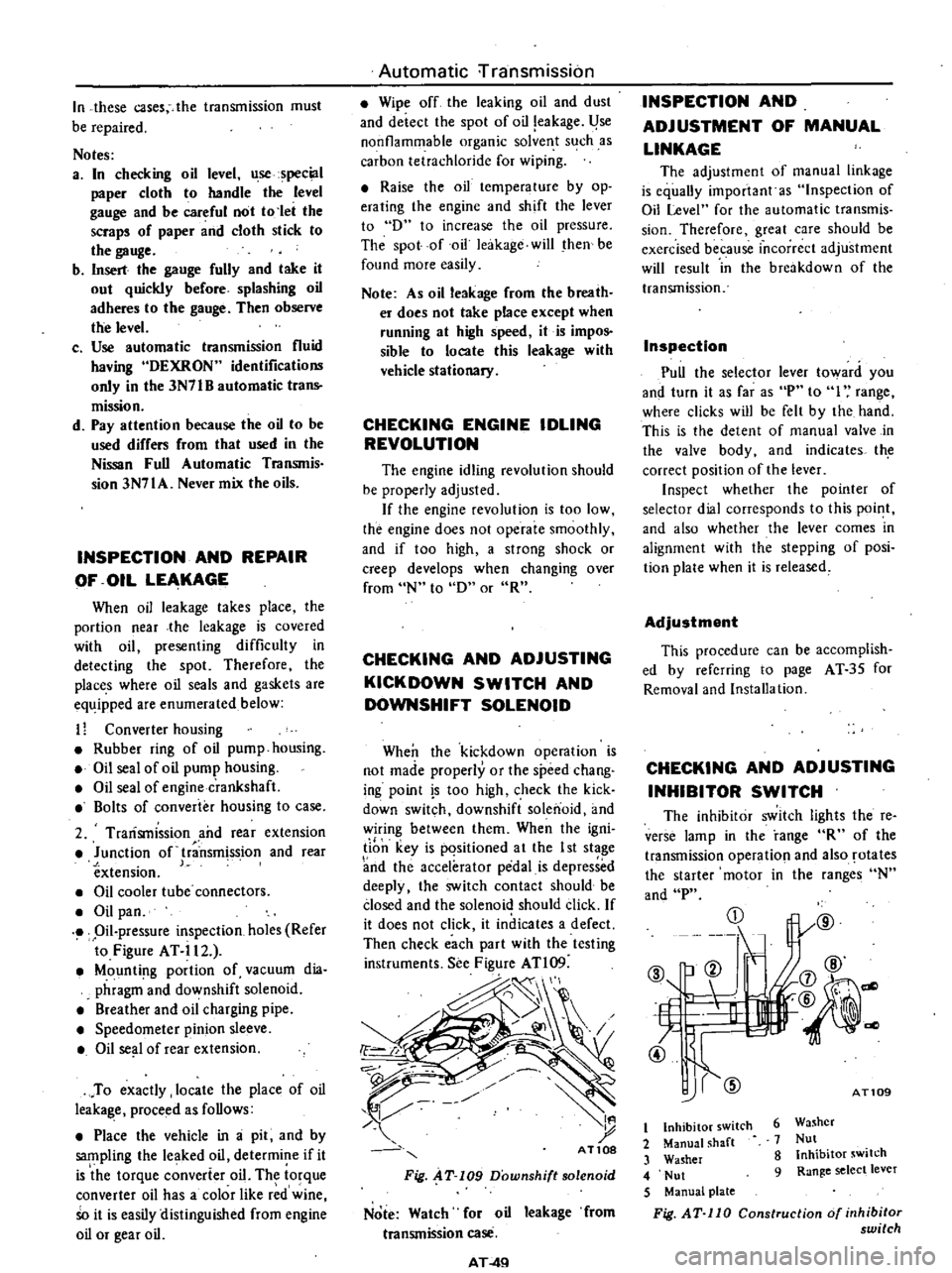
When
the
kickdown
operation
is
not
made
properly
or
the
speed
chang
ing
point
s
too
high
check
the
kick
down
switch
downshift
solenoid
and
wiring
between
them
When
the
igni
li
n
key
is
pqsitioned
a
t
the
I
st
stage
nd
the
accelerator
pedal
is
depressed
deeply
the
switch
contact
should
be
closed
and
the
solenoid
should
click
If
it
does
not
click
it
indicates
a
defect
Then
check
each
part
with
the
testing
instruments
See
Figure
ATl09
d
I
t
AT10S
Fig
AT
109
Downshift
solenoid
Note
Watch
for
oil
leakage
from
transmission
case
AT
4Q
INSPECTION
AND
ADJUSTMENT
OF
MANUAL
LINKAGE
The
adjustmcnt
of
manual
linkage
is
equaUy
important
as
Inspection
of
Oil
Level
for
the
automatic
transmis
sion
Thereforc
great
care
should
be
exercised
because
incorrect
adjustment
will
rcsult
in
the
brcakdown
of
the
transmission
Inspection
Pull
the
selector
lever
toward
you
and
turn
it
as
far
as
P
to
I
range
wherc
clicks
will
be
felt
by
the
hand
This
is
the
detcnt
of
manual
valve
in
the
valve
body
and
indicates
th
correct
position
of
the
lever
Inspect
whether
the
pointer
of
selector
dial
corresponds
to
this
point
and
also
whether
the
lever
comes
in
alignment
with
the
stepping
of
posi
tion
plate
when
it
is
released
Adjustment
This
procedure
can
be
accomplish
ed
by
refcrring
to
page
AT
35
for
Removal
and
Installa
tion
CHECKING
AND
ADJUSTING
INHIBITOR
SWITCH
The
inhibitor
switch
lights
the
re
verse
lamp
in
the
range
R
of
the
transmission
operatio
l
and
also
rotates
the
starter
motor
in
the
ranges
N
and
P
CD
@
b
ell
If
L
t
7
4l
@
1l
j7
@
@
@
dl
AT109
6
Washer
7
Nut
8
Inhibitor
switch
9
Range
select
lever
t
Inhibitor
switch
2
Manual
shaft
3
Washer
4
Nut
5
Manual
plate
Fig
AT
110
Construction
of
inhibitor
switch
Page 458 of 537
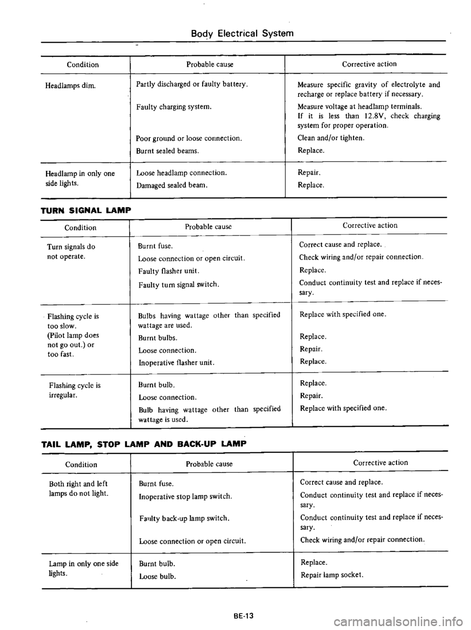
Condition
Headiamps
dim
Headlamp
in
only
one
side
lights
TURN
SIGNAL
LAMP
Condition
Turn
signals
do
not
operate
Flashing
cycle
is
too
slow
Pilot
lamp
does
not
go
out
or
too
fast
Flashing
cycle
is
irregular
Body
Electrical
System
Probable
cause
Partly
discharged
or
faulty
battery
Faulty
charging
system
Poor
ground
or
loose
connection
Burnt
sealed
beams
Loose
headlamp
connection
Damaged
sealed
beam
Probable
cause
Burnt
fuse
Loose
connection
or
open
circuit
Faulty
flasher
unit
Faulty
turn
signal
switch
Bulbs
having
wattage
other
than
specified
wattage
are
used
Burnt
bulbs
Loose
connection
Inoperative
flasher
unit
Burnt
bulb
Loose
connection
Bulb
having
wattage
other
than
specified
wa
ttage
is
used
TAIL
LAMP
STOP
LAMP
AND
BACK
UP
LAMP
Condition
Both
right
and
left
lamps
do
not
light
Lamp
in
only
one
side
lights
Probable
cause
Burnt
fuse
Inoperative
stop
lamp
switch
Falllty
back
up
lamp
switch
Loose
connection
or
open
circuit
Burnt
bulb
Loose
bulb
BE13
Corrective
action
Measure
specific
gravity
of
electrolyte
and
recharge
or
replace
battery
if
necessary
Measure
voltage
at
headlamp
terminals
If
it
is
less
than
12
8V
check
charging
system
for
proper
operation
Clean
and
or
tighten
Replace
Repair
Replace
Corrective
action
Correct
cause
and
replace
Check
wiring
and
or
repair
connection
Replace
Conduct
continuity
test
and
replace
if
neces
sary
Replace
with
specified
one
Replace
Repair
Replace
Replace
Repair
Replace
with
specified
one
Corrective
action
Correct
cause
and
replace
Conduct
continuity
test
and
replace
if
neces
sary
Conduct
continuity
test
and
replace
if
neces
sary
Check
wiring
and
or
repair
connection
Replace
Repair
lamp
socket
Page 465 of 537
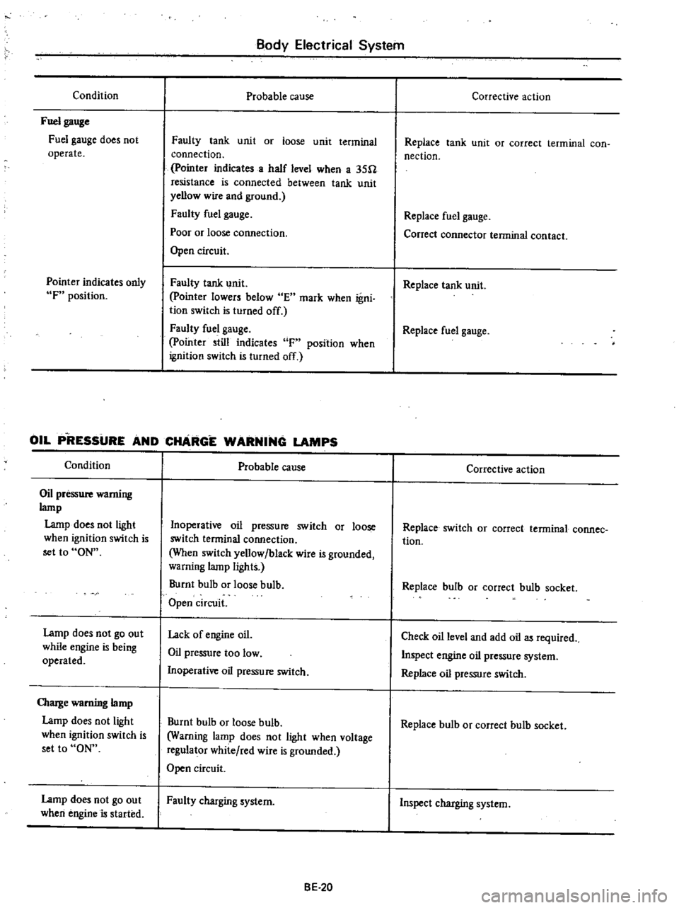
Condition
Fuel
gauge
Fuel
gauge
does
not
operate
Pointer
indicates
only
F
position
Body
Electrical
System
Probable
cause
Faulty
tank
unit
or
loose
unit
terminal
connection
pointer
indicates
a
half
level
when
a
35U
resistance
is
connected
between
tank
unit
yellow
wire
and
ground
Faulty
fuel
gauge
Poor
or
loose
cormection
Open
circuit
Faulty
tank
unit
pointer
lowers
below
E
mark
when
igni
tion
switch
Is
turned
off
Faulty
fuel
gauge
pointer
still
indicates
F
position
when
ignition
switch
is
turned
off
OIL
P
RESSURE
AND
CHARGE
WARNING
LAMPS
Condition
Oil
pressure
wamiug
lamp
Lamp
does
not
light
when
ignition
switch
is
set
to
ON
Lamp
does
not
go
out
while
engine
is
being
operated
OIarge
warning
lamp
Lamp
does
not
light
when
ignition
switch
is
set
to
ON
Lamp
does
not
go
out
when
engine
is
started
Probable
cause
Inoperative
oil
pressure
switch
or
loose
switch
terminal
connection
When
switch
yellow
black
wire
is
grounded
warning
lamp
lights
Burnt
bulb
or
loose
bulb
Open
circuit
Lack
of
engine
oil
Oil
pressure
too
low
Inoperative
oil
pressure
switch
Burnt
bulb
or
loose
bulb
Warning
lamp
does
not
light
when
voltage
regulator
white
red
wire
is
grounded
Open
circuit
Faulty
charging
system
BE
20
Corrective
action
Replace
tank
unit
or
correct
terminal
con
nection
Replace
fuel
gauge
Conect
connector
terminal
contact
Replace
tank
unit
Replace
fuel
gauge
Corrective
action
Replace
switch
OJ
correct
terminal
connee
tion
Replace
bulb
or
correct
bulb
socket
Check
oil
level
and
add
oil
as
required
Inspect
engine
oil
pressure
system
Replace
oil
pressure
switch
Replace
bulb
or
correct
bulb
socket
Inspect
charging
system