tow bar DATSUN PICK-UP 1977 Service Manual
[x] Cancel search | Manufacturer: DATSUN, Model Year: 1977, Model line: PICK-UP, Model: DATSUN PICK-UP 1977Pages: 537, PDF Size: 35.48 MB
Page 92 of 537

The
pump
shaft
is
supported
by
a
double
row
of
ball
bearings
press
fit
in
an
aluminum
die
cast
pump
body
The
bearings
are
permanently
lubricated
and
sealed
to
prevent
loss
of
lubricant
and
entry
of
dirt
The
pump
is
provided
with
an
impeller
which
turns
on
a
steel
shaft
The
steel
shaft
rotates
together
with
the
torque
coupling
wheeL
The
volute
chamber
is
built
in
the
engine
front
cover
assembly
The
inlet
of
the
pump
is
connected
to
the
radiator
s
lower
tank
by
a
hose
i
o
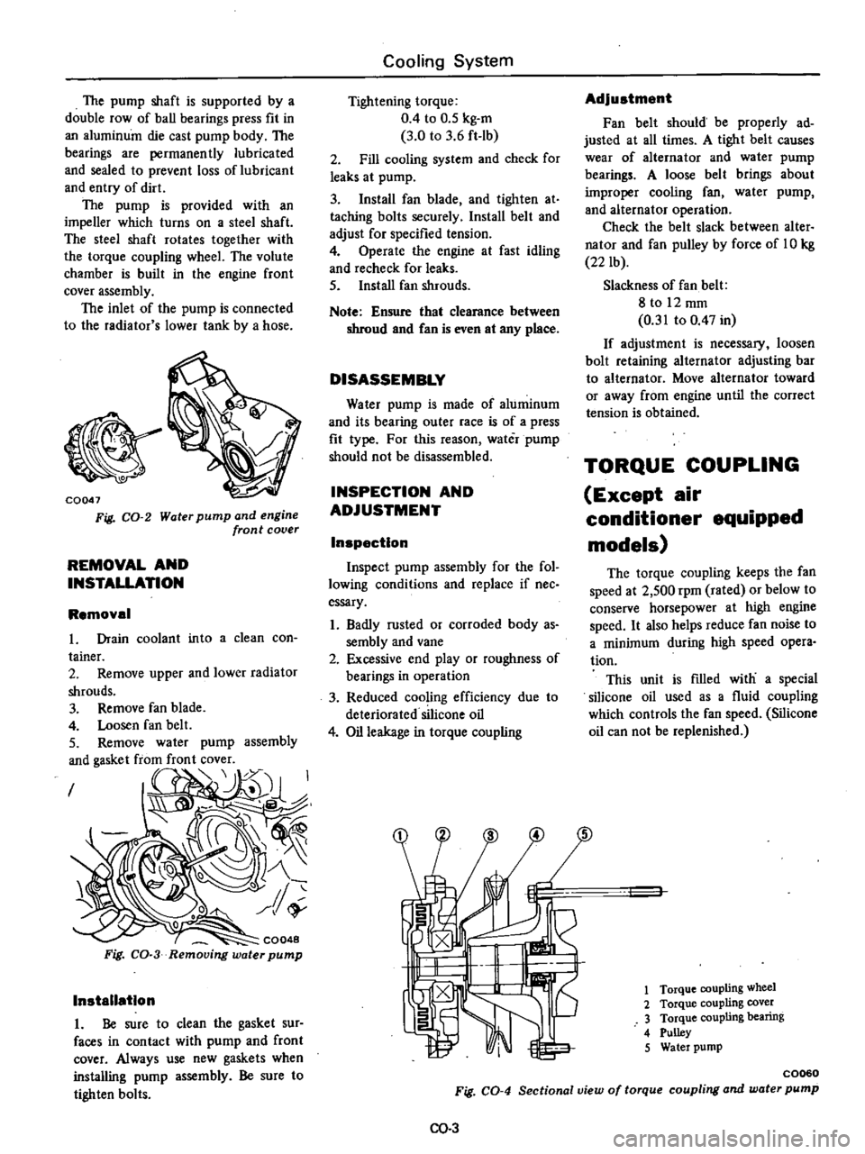
CQ047
Fig
CO
2
Water
pump
and
engine
front
cover
REMOVAL
AND
INSTALLATION
Removal
in
to
a
clean
con
assembly
I
CQ048
Fig
CO
3
Removing
water
pump
Installation
1
Be
sure
to
clean
the
gasket
sur
faces
in
contact
with
pump
and
front
cover
Always
use
new
gaskets
when
installing
pump
assembly
Be
sure
to
tighten
bolts
Cooling
System
Tightening
torque
0
4
to
0
5
kg
m
3
0
to
3
6
ft
lb
2
Fill
cooling
system
and
check
for
leaks
at
pump
3
Install
fan
blade
and
tighten
at
taching
bolts
securely
Install
belt
and
adjust
for
specified
tension
4
Operate
the
engine
at
fast
idling
and
recheck
for
leaks
5
Install
fan
shrouds
Note
Ensure
that
clearance
between
shroud
and
Can
is
even
at
any
place
DISASSEMBLY
Water
pump
is
made
of
aluminum
and
its
bearing
outer
race
is
of
a
press
fit
type
For
this
reason
water
pump
should
not
be
disassembled
INSPECTION
AND
ADJUSTMENT
Inspection
Inspect
pump
assembly
for
the
fol
lowing
conditions
and
replace
if
nee
essary
1
Badly
rusted
or
corroded
body
as
sembly
and
vane
2
Excessive
end
play
or
roughness
of
bearings
in
operation
3
Reduced
cooling
efficiency
due
to
deteriorated
silicone
oil
4
Oil
leakage
in
torque
coupling
Adjustment
Fan
belt
should
be
properly
ad
justed
at
all
times
A
tight
belt
causes
wear
of
alternator
and
water
pump
bearings
A
loose
belt
brings
about
improper
cooling
fan
water
pump
and
alternator
operation
Check
the
belt
slack
between
alter
nator
and
fan
pulley
by
force
of
10
kg
22
lb
Slackness
of
fan
belt
8
to
12
mm
0
31
to
0
47
in
If
adjustment
is
necessary
loosen
bolt
retaining
alternator
adjusting
bar
to
alternator
Move
alternator
toward
or
away
from
engine
until
the
correct
tension
is
obtained
TORQUE
COUPLING
Except
air
conditioner
equipped
models
The
torque
coupling
keeps
the
fan
speed
at
2
500
rpm
rated
or
below
to
conserve
horsepower
at
high
engine
speed
It
also
helps
reduce
fan
noise
to
a
minimum
during
high
speed
opera
tion
This
unit
is
filled
with
a
special
silicone
oil
used
as
a
fluid
coupling
which
controls
the
fan
speed
Silicone
oil
can
not
be
replenished
1
Torque
coupling
wheel
2
Torque
coupling
cover
3
Torque
coupling
bearing
4
Pulley
5
Water
pump
C0060
Fig
CO
4
Sectional
view
of
torque
coupling
and
water
pump
00
3
Page 202 of 537

Vacuum
advance
mechanism
mechanical
parts
If
vacuum
advance
mechanism
fails
to
operate
properly
check
for
the
following
items
and
correct
the
prob
lem
as
required
1
Check
vacuum
inlet
for
signs
of
leakage
at
its
connection
If
necessary
retighten
or
replace
with
a
new
one
2
Check
vacuum
diaphragm
for
air
leak
If
leak
is
found
replace
vacuum
controller
assembly
3
Inspect
breaker
plate
for
smooth
moving
If
plate
does
not
move
smoothly
this
condition
could
be
due
to
sticky
steel
balls
or
pivot
Apply
grease
to
steel
balls
or
if
necessary
replace
distributor
assembly
Centrifugal
advance
mechanical
parts
When
cause
of
engine
malfunction
is
traced
to
centrifugal
advance
mecha
nical
parts
use
distributor
tester
to
check
its
characteristics
See
to
the
specifications
above
If
nothing
is
wrong
with
its
charac
teristics
conceivable
causes
are
faulty
or
abnormal
wear
of
driving
part
or
others
So
do
not
disassemble
it
In
the
event
of
improper
character
istics
check
closely
rotor
shaft
assem
bly
governor
weight
and
shaft
If
any
of
above
parts
are
malfunc
tioning
replace
distributor
assembly
DISASSEMBLY
To
disassemble
follow
the
pro
cedure
below
1
Take
off
cap
and
remove
rotor
head
2
Remove
two
screws
shown
in
Figure
EE
69
and
detach
vacuum
con
troller
Engine
Electrical
System
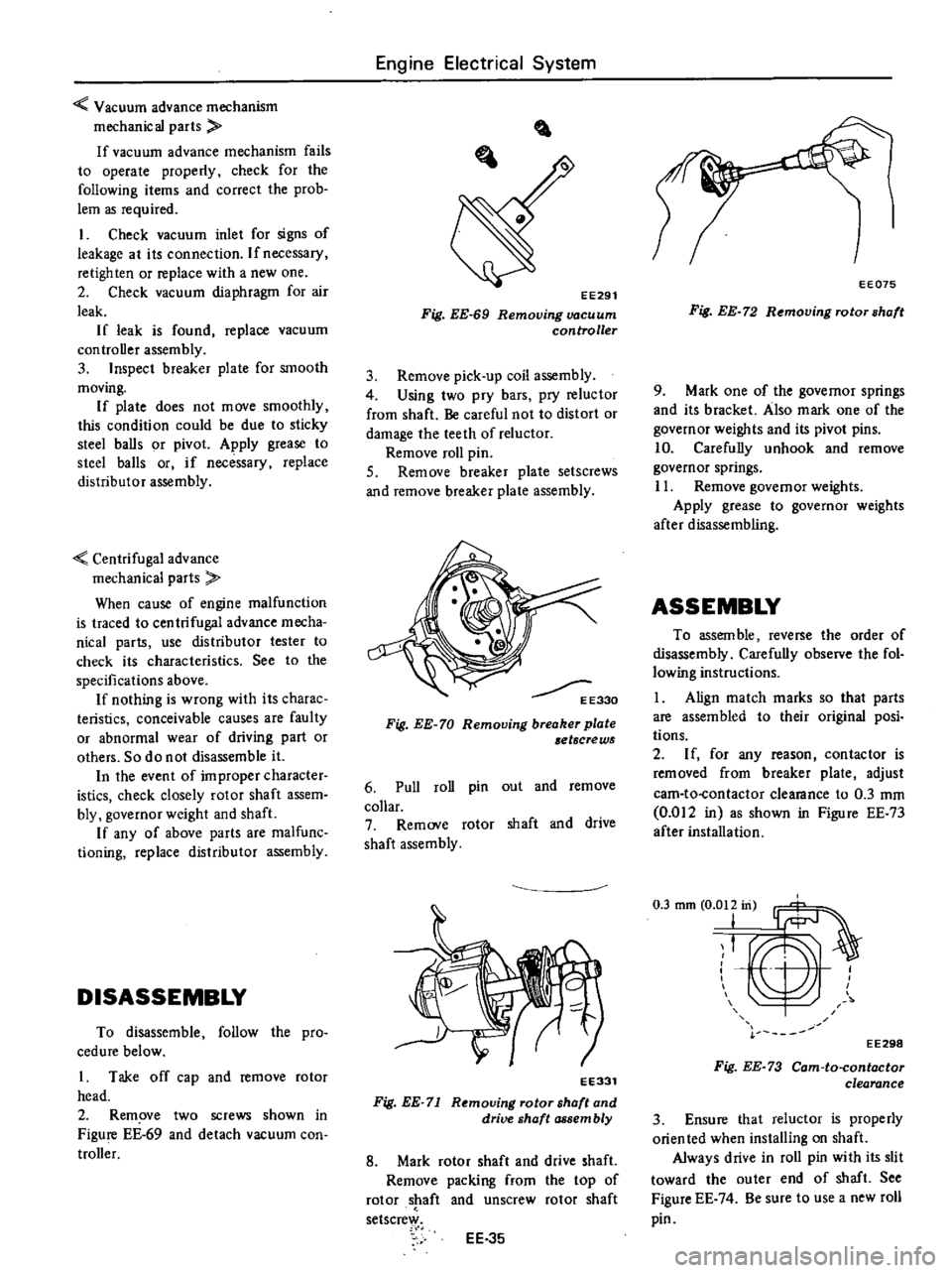
EE291
Fig
EE
69
Removing
vacuum
controller
3
Remove
pick
up
coil
assembly
4
Using
two
pry
bars
pry
reluctor
from
shaft
Be
careful
not
to
distort
or
damage
the
teeth
of
reluctor
Remove
roll
pin
S
Remove
breaker
plate
setscrews
and
remove
breaker
plate
assembly
E330
Fig
EE
70
Removing
breaker
plate
etscrews
6
Pull
roll
pin
out
and
remove
collar
7
Remove
rotor
shaft
and
drive
shaft
assembly
EE331
Fig
EE
71
Removing
rotor
shaft
and
drive
shaft
assembly
8
Mark
rotor
shaft
and
drive
shaft
Remove
packing
from
the
top
of
rotor
shaft
and
unscrew
rotor
shaft
setscrew
EE
35
EE075
Fig
EE
72
Removing
rotor
shaft
9
Mark
one
of
the
governor
springs
and
its
bracket
Also
mark
one
of
the
governor
weights
and
its
pivot
pins
10
Carefully
unhook
and
remove
governor
springs
11
Remove
governor
weights
Apply
grease
to
governor
weights
after
disassembling
ASSEMBLY
To
assem
ble
reverse
the
order
of
disassembly
Carefully
observe
the
fol
lowing
instructions
1
Align
match
marks
so
that
parts
are
assembled
to
their
original
posi
tions
2
If
for
any
reason
contactor
is
removed
from
breaker
plate
adjust
cam
to
contactor
clearance
to
0
3
mm
0
012
in
as
shown
in
Figure
EE
73
after
installation
T
EE298
Fig
EE
73
Cam
to
contactor
clearance
3
Ensure
that
reluctor
is
properly
orien
ted
when
installing
on
shaft
Always
drive
in
roll
pin
with
its
slit
toward
the
outer
end
of
shaft
See
Figure
EE
74
Be
sure
to
use
a
new
roll
pin
Page 266 of 537

the
space
from
I
to
IS
increases
space
from
15
to
the
drain
port
simultaneously
decreases
As
a
resull
governor
pressure
of
15
increases
and
the
governor
pressure
is
balanced
with
the
sum
of
centrifugal
force
and
spring
force
The
governor
pressure
thus
changes
in
response
to
the
vehicle
speed
change
centrifugal
force
Operation
of
prlmar
governor
valve
The
valve
is
an
ON
OFF
valve
which
closes
the
governor
pressure
IS
regulated
by
the
secondary
gover
nor
valve
when
the
vehicle
reaches
the
minimum
speed
and
when
the
vehicle
speed
exceeds
a
certain
level
the
governor
opens
and
forwards
the
gov
ernor
pressure
15
to
the
control
valve
When
the
vehicle
is
stopped
the
governor
pressure
is
zero
However
when
the
vehicle
is
running
slowly
this
valve
is
depressed
to
Ihe
center
and
the
groove
to
15
is
closed
since
the
governor
pressure
applied
to
the
ring
shaped
area
is
higher
than
the
centrifugal
force
of
this
valve
When
the
governor
speed
exceeds
a
certain
revolution
the
governor
pressure
in
the
circuit
15
also
increases
How
ever
as
the
centrifugal
force
increases
and
exceeds
the
governor
pressure
this
valve
moves
toward
the
outside
and
the
governor
pressure
is
transmitted
to
the
circuil
5
Two
different
valves
are
employed
in
the
governor
so
that
it
will
inde
pendently
control
the
speed
at
high
and
low
speeds
That
is
within
the
low
speed
range
the
governor
pressure
is
not
generated
because
of
the
primary
valve
whereas
at
the
high
speed
range
above
the
breaking
point
governor
pressure
is
regulated
by
the
secondary
valve
The
breaking
point
is
the
point
at
which
the
function
of
one
of
the
governor
is
transferred
to
the
other
as
the
speed
changes
from
the
low
speed
to
the
high
speed
range
Automatic
Transmission
To
onlml
valve
l
Governor
pre
S1I
1I5
j
I
Q
J
J
f
1
1
CID
l
l
m
Line
pressure
t
D@
I
Primary
governor
2
Secondary
governor
3
Governor
valve
body
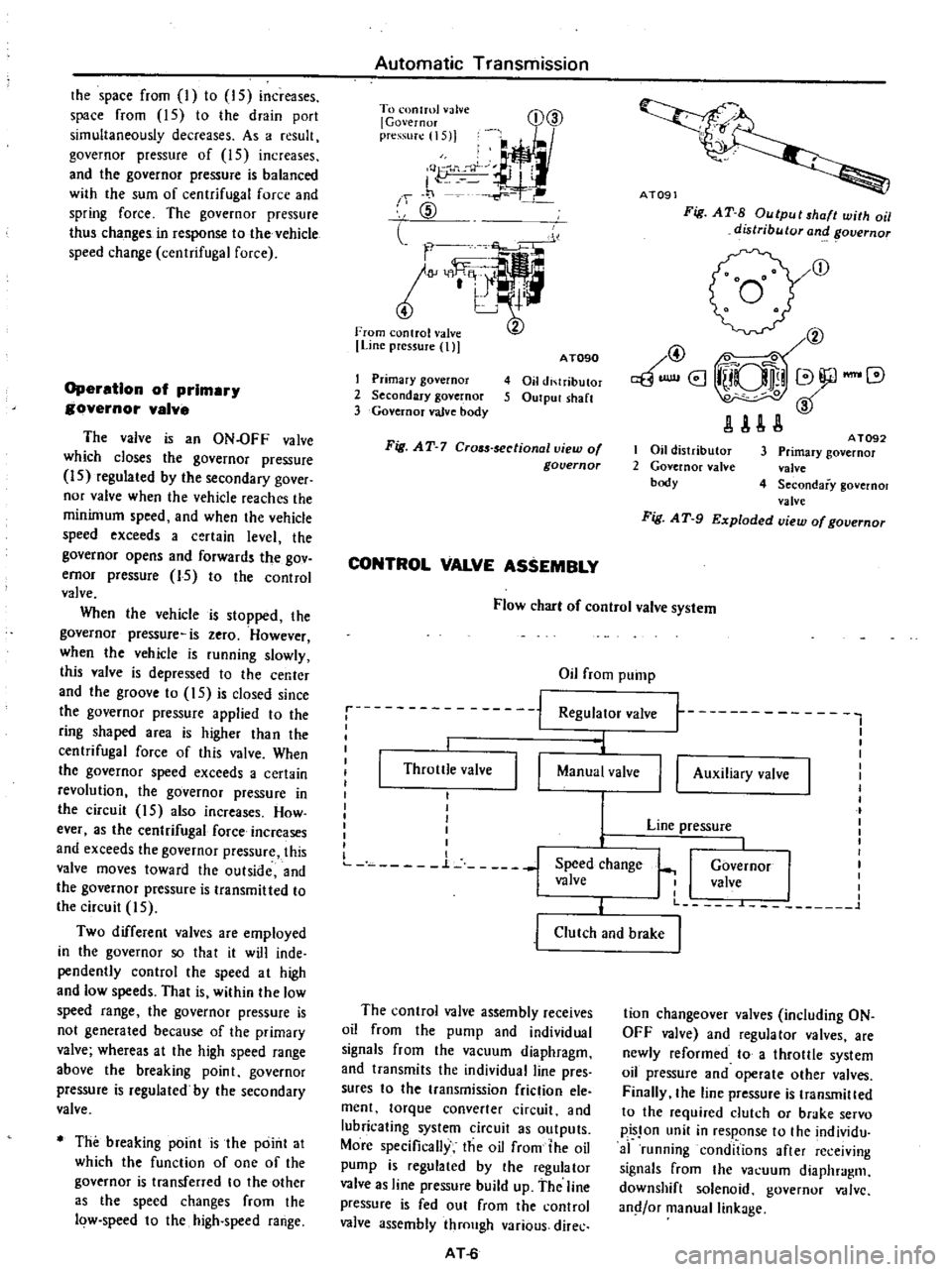
AT090
4
Oil
di
lributor
5
Output
sh
lft
Fig
AT
7
Cr05s
sectionallliew
of
governor
CONTROL
VALVE
ASSEMBLY
Ai09
Fig
AT
S
Output
shaft
with
oil
distributor
and
overnor
r
@
@
0
aBUlllI8
iUQlli
V
JlAU
I
Oil
distributor
2
Governor
nlve
body
A
T092
3
Primary
governor
valve
4
Secondary
governol
valve
Fig
A
T
9
Exploded
view
of
governor
Flow
cbar
of
control
valve
system
Oil
from
pump
Regulator
valve
1
I
i
j
Throttle
valve
I
I
l
Manual
valve
I
I
I
I
I
I
I
L
n
L
j
Speed
change
valve
I
I
t
t
I
I
I
I
I
I
Governor
I
I
valve
I
I
I
L
L
1
II
Auxiliary
valve
Line
pressure
j
Clutch
and
brake
The
control
valve
assembly
receives
oil
from
the
pump
and
individual
signals
from
the
vacuum
diaphragm
and
transmits
the
individual
line
pres
sures
to
the
transmission
friction
ele
ment
torque
converter
circuit
and
lubricating
system
circuit
as
outputs
More
specifically
the
oil
from
the
oil
pump
is
regulated
by
the
regulator
valve
as
line
pressure
build
up
the
line
pressure
is
fed
out
from
the
control
valve
assembly
through
various
direc
AT
6
tion
changeover
valves
including
ON
OFF
valve
and
regulator
valves
are
newly
reformed
to
a
throllle
system
oil
pressure
and
operate
other
valves
Finally
the
line
pressure
is
transmilled
to
the
required
dutch
or
brake
servo
pisJon
unit
in
response
to
the
individu
af
running
conditions
after
re
ejving
signals
from
the
va
uum
diaphragm
downshift
solenoid
governor
V
dlvc
and
or
manual
linkage