tow DATSUN PICK-UP 1977 Service Manual
[x] Cancel search | Manufacturer: DATSUN, Model Year: 1977, Model line: PICK-UP, Model: DATSUN PICK-UP 1977Pages: 537, PDF Size: 35.48 MB
Page 6 of 537
General
Information
L
GENERAL
INFORMATION
CONTENTS
MOOEL
VARIATION
GI
3
APPROXIMATE
REFILL
CAPACITIES
GI
B
IDENTIFICATION
NUMBERS
GI
5
RECOMMENDED
FUEL
GI
B
LIFTING
POINTS
AND
TOWING
GI
B
RECOMMENDED
LUBRICANTS
GI
8
LIFTING
POINTS
GI
B
RECOMMENDED
SAE
VISCOSITY
SUPPORTABLE
POINTS
GI
7
NUMBER
GI
8
TOWING
GI
7
LUBRICANT
SPECIFICATIONS
GI
g
TIE
DOWN
GI
7
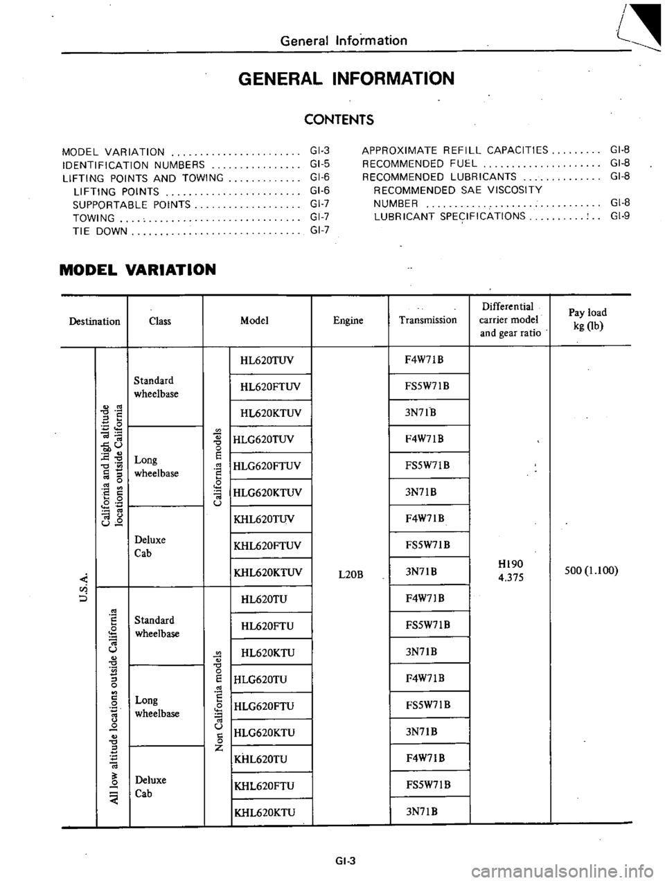
MODEL
VARIATION
Differential
Pay
load
Destination
Class
Model
Engine
Transmission
carrier
model
kg
Ob
and
gear
ratio
I
HL620TUV
F4W7lB
Standard
I
HL620FTUV
FS5W71
B
wheelbase
S
I
HL620KTUV
3N7lB
E
I
HLG620TUV
Ol
F4W7lB
u
0
0
E
Long
E
I
HLG620FTUV
0
FS5W71B
wheelbase
0
I
HLG620KTUV
8
a
3N7lB
0
Ol
0
u
I
KHL620TUV
Ol
F4W7lB
u
Deluxe
I
KHL620FTUV
FS5W7lB
Cab
KHL620KTUV
3N7lB
Hl90
500
1
1
00
L20B
4
375
u
i
0
HL620TU
F4W71
B
Standard
HL620FTU
FS5W7l
B
wheelbase
U
HL620KTU
3N7lB
S
0
I
HLG620TU
0
E
F4W7lB
0
8
Long
I
HLG620FTU
0
FS5W7lB
wheelbase
IHLG620KTU
Q
u
3N7lB
0
0
Z
KHL620TU
F4W71B
Deluxe
Q
KHL620FTU
FS5W7l
B
Cab
I
KHL620KTU
3N7lB
GI
3
Page 9 of 537
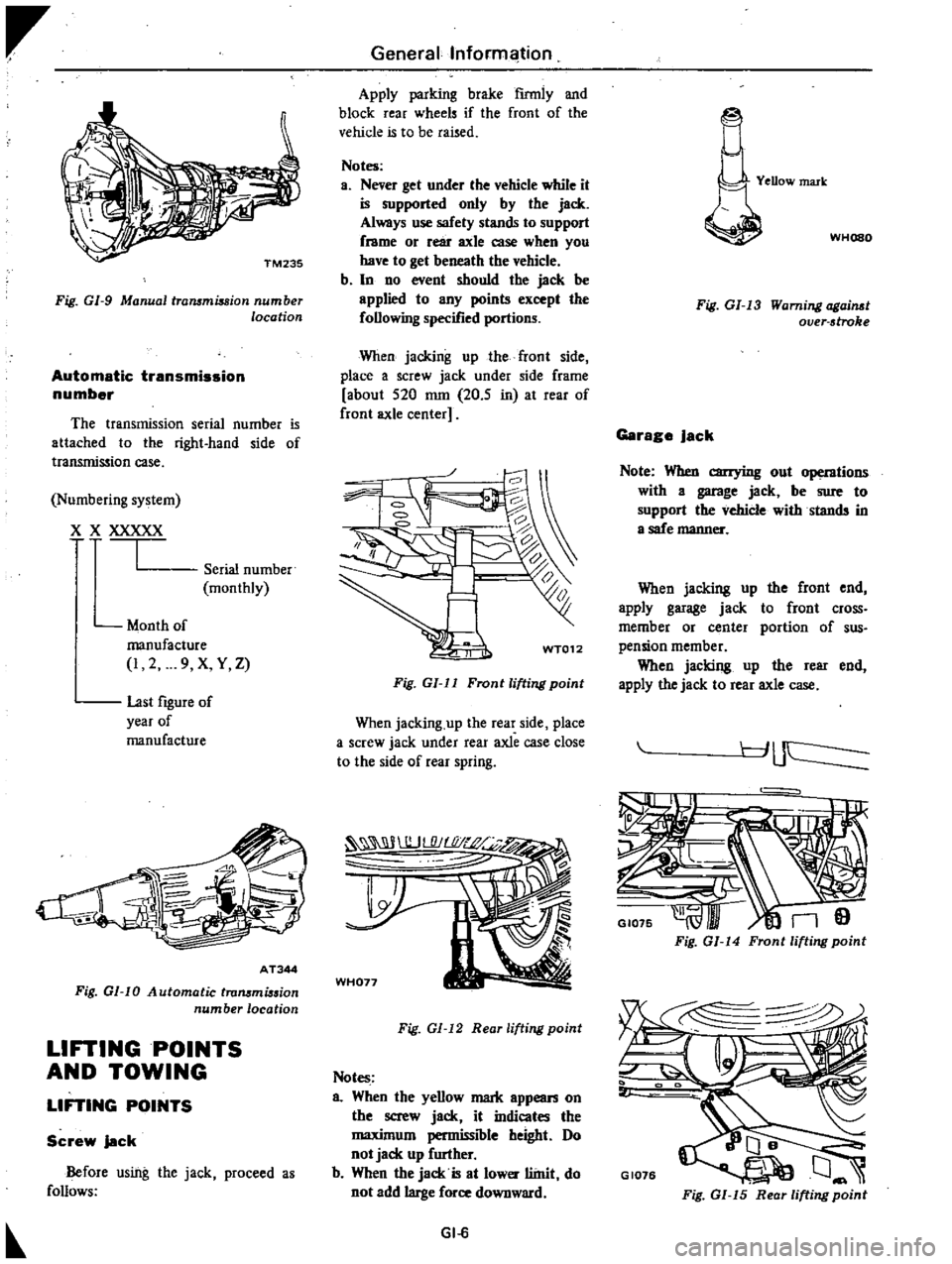
Fig
GI
9
Manual
trammiuion
number
location
Automatic
transmission
number
The
transmission
serial
number
is
attached
to
the
right
hand
side
of
transmission
case
Numbering
system
X
XXXXX
I
Serial
number
monthly
Month
of
manufacture
I
2
9
X
Y
Z
last
figure
of
year
of
manufacture
AT344
Fig
01
10
Automatic
trammi
sion
number
location
LIFTING
POINTS
AND
TOWING
LIFTING
POINTS
Screw
jack
Before
using
the
jack
proceed
a
follows
Generallnforml
ition
Apply
parking
brake
firmly
and
block
rear
wheels
if
the
front
of
the
vehicle
is
to
be
raised
Notes
a
Never
get
under
the
vehicle
while
it
is
supported
only
by
the
jack
Always
use
safety
stands
to
support
frame
or
rear
axle
case
when
you
have
to
get
beneath
the
vehicle
b
In
no
event
should
the
jack
be
applied
to
any
points
except
the
following
specified
portions
When
jacking
up
the
front
side
place
a
screw
jack
under
side
frame
about
520
nun
20
5
in
at
rear
of
front
axle
center
WT012
Fig
GI
ll
Front
lifting
point
When
jacking
up
the
rear
side
place
a
screw
jack
under
rear
axle
case
close
to
the
side
of
rear
spring
WH077
Fig
GI
12
Reor
lifting
point
Notes
a
When
the
yellow
mark
appean
on
the
screw
jack
it
indicates
the
maximum
permissible
height
Do
not
jack
up
further
b
When
the
jack
is
at
lower
llinit
do
not
add
large
force
downward
GI
6
YeDow
mark
WHOSO
Fig
GI
13
Warning
ogai
t
over
stroke
Garage
Jack
Note
When
carrying
out
operntions
with
a
garage
jack
be
sure
to
support
the
vehicle
withstands
in
a
safe
manner
When
jacking
up
the
front
end
apply
garage
jack
to
front
cross
member
or
center
portion
of
sus
pension
member
When
jacking
up
the
rear
end
apply
the
jack
to
rear
axle
case
r
J
uc
I
GI075
n9
Fig
GI
14
Front
lifting
point
GI076
Fig
GI
15
Rear
lifting
point
Page 10 of 537
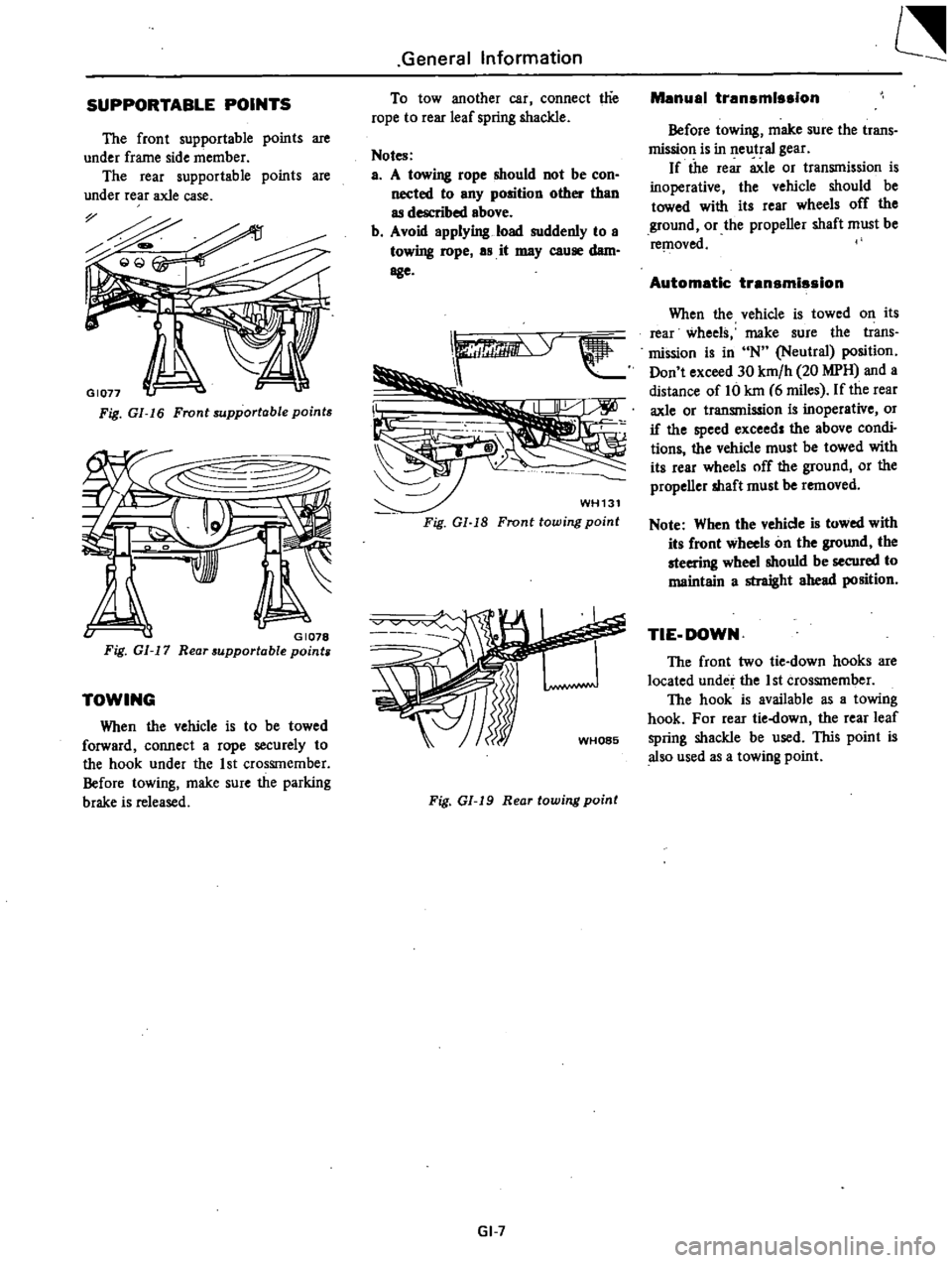
SUPPORTABLE
POINTS
The
front
supportable
points
are
under
frame
side
member
The
rear
supportable
points
are
under
rear
axle
case
Fig
GI
16
Front
supportable
points
v
GI078
Fig
GI
17
Rear
supportable
points
TOWING
When
the
vehicle
is
to
be
towed
forward
connect
a
rope
securely
to
the
hook
under
the
1st
CrosSIn
ember
Before
towing
make
sure
the
parking
brake
is
released
General
Information
To
tow
another
car
connect
t1ie
rope
to
rear
leaf
spring
shackle
Notes
a
A
towing
rope
should
not
be
con
nected
to
any
position
other
than
as
described
above
b
Avoid
applying
load
suddenly
to
a
towing
rope
as
it
may
cause
dam
age
WH131
Fig
Gl
18
Fronttowing
point
Fig
01
19
Rear
towing
point
GI
7
Manual
transmission
Before
towing
make
sure
the
trans
mission
is
in
neutral
gear
If
the
rear
axle
or
transmission
is
inoperative
the
vehicle
should
be
towed
with
its
rear
wheels
off
the
ground
or
the
propeller
shaft
must
be
re
l1oved
Automatic
transmission
When
the
vehicle
is
towed
on
its
rear
wheels
make
sure
the
trans
mission
is
in
N
Neutral
position
Don
t
exceed
30
km
h
20
MPH
and
a
distance
of
Hi
kin
6
miles
If
the
rear
axle
or
transmission
is
inoperative
or
if
the
speed
exceed
the
above
condi
tions
the
vehicle
must
be
towed
with
its
rear
wheels
off
the
ground
or
the
propeller
shaft
must
be
removed
Note
When
the
vehicle
is
towed
with
its
front
wheels
on
the
ground
the
steering
wheel
shouId
be
secured
to
maintain
a
straight
ahead
position
TIE
DOWN
The
front
two
tie
down
hooks
are
located
under
the
1st
crosSInember
The
hook
is
available
as
a
towing
hook
For
rear
tie
down
the
rear
leaf
spring
shackle
be
used
lIDs
point
is
also
used
as
a
towing
point
Page 23 of 537
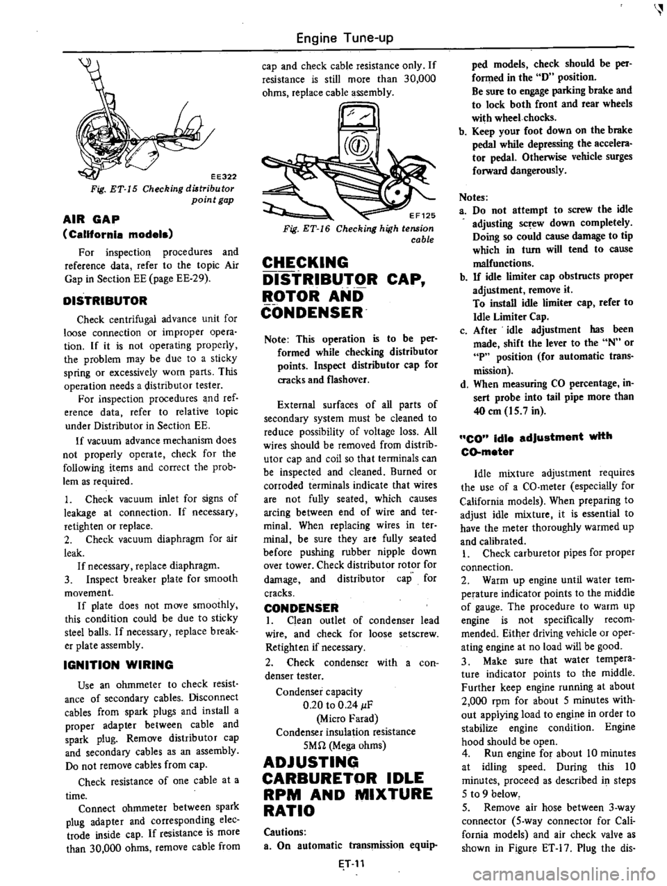
EE322
Fig
ET
15
Checking
diltribu
tor
point
gap
AIR
GAP
California
models
For
inspection
procedures
and
reference
data
refer
to
the
topic
Air
Gap
in
Section
EE
page
EE
29
DISTRIBUTOR
Check
centrifugal
advance
unit
for
loose
connection
or
improper
opera
tion
If
it
is
not
operating
properly
the
problem
may
be
due
to
a
sticky
spring
or
excessively
worn
parts
This
operation
needs
a
distributor
tester
For
inspection
procedures
and
ref
erence
data
refer
to
relative
topic
under
Distributor
in
Section
EE
If
vacuum
advance
mechanism
does
not
properly
operate
check
for
the
following
items
and
correct
the
prob
lem
as
required
1
Check
vacuum
inlet
for
signs
of
leakage
at
connection
If
necessary
retighten
or
replace
2
Check
vacuum
diaphragm
for
air
leak
If
necessary
replace
diaphragm
3
Inspect
breaker
plate
for
smooth
movement
If
plate
does
not
move
smoothly
this
condition
could
be
due
to
sticky
steel
balls
If
necessary
replace
break
er
plate
assembly
IGNITION
WIRING
Use
an
ohmmeter
to
check
resist
ance
of
secondary
cables
Disconnect
cables
from
spark
plugs
and
install
a
proper
adapter
between
cable
and
spark
plug
Remove
distributor
cap
and
secondary
cables
as
an
assembly
Do
not
remove
cables
from
cap
Check
resistance
of
one
cable
at
a
time
Connect
ohmmeter
between
spark
plug
adapter
and
corresponding
elec
trade
inside
cap
If
resistance
is
more
than
30
000
ohms
remove
cable
from
Engine
Tune
up
cap
and
check
cable
resistance
only
If
resistance
is
still
more
than
30
000
ohms
replace
cable
assembly
EF125
Checking
high
tension
cable
CHECKING
DISTRIBUTOR
CAP
ROTOR
AND
CONDENSER
Note
This
operation
is
to
be
per
formed
while
checking
distributor
points
Inspect
distributor
cap
for
cracks
and
flashover
External
surfaces
of
all
parts
of
secondary
system
must
be
cleaned
to
reduce
possibility
of
voltage
loss
All
wires
should
be
removed
from
distrib
utor
cap
and
coil
so
that
terminals
can
be
inspected
and
cleaned
Burned
or
corroded
terminals
indicate
that
wires
are
not
fully
seated
which
causes
arcing
between
end
of
wire
and
ter
minal
When
replacing
wires
in
ter
minai
be
sure
they
are
fully
seated
before
pushing
rubber
nipple
down
over
tower
Check
distributor
rotor
for
damage
and
distributor
cap
for
cracks
CONDENSER
I
Clean
outlet
of
condenser
lead
wire
and
check
for
loose
setscrew
Retighten
if
necessary
2
Check
condenser
with
a
con
denser
tester
Condenser
capacity
0
20
to
0
24
IF
Micro
Farad
Condenser
insulation
resistance
5Mn
Mega
ohms
ADJUSTING
CARBURETOR
IDLE
RPM
AND
MIXTURE
RATIO
Cautions
a
On
automatic
transmission
equip
T
11
ped
models
check
should
be
per
fonned
in
the
D
position
Be
sure
to
engage
parking
brake
and
to
lock
both
front
and
rear
wheels
with
wheel
chocks
b
Keep
your
foot
down
on
the
brake
pedal
while
depressing
the
accelera
tor
pedal
Otherwise
vehicle
surges
forward
dangerously
Notes
a
Do
not
attempt
to
screw
the
idle
adjusting
sc
ew
down
completely
Doing
so
could
cause
damage
to
tip
which
in
turn
will
tend
to
cause
malfunctions
b
If
idle
limiter
cap
obstructs
proper
adjustment
remove
it
To
install
idle
limiter
cap
refer
to
Idle
Limiter
Cap
c
After
idle
adjustment
has
been
made
shift
the
lever
to
the
N
or
P
position
for
automatic
trans
mission
d
When
measuring
CO
percentage
in
sert
probe
into
tail
pipe
more
than
40
em
15
7
in
CO
idle
adjustment
with
CD
meter
Idle
mixture
adjustment
requires
the
use
of
a
CO
meter
especially
for
California
models
When
preparing
to
adjust
idle
mixture
it
is
essential
to
have
the
meter
thoroughly
warmed
up
and
calibrated
I
Check
carburetor
pipes
for
proper
connection
2
Warm
up
engine
until
water
tem
perature
indicator
points
to
the
middle
of
gauge
The
procedure
to
warm
up
engine
is
not
specifically
recom
mended
Either
driving
vehicle
or
oper
ating
engine
at
no
load
will
be
good
3
Make
sure
that
water
tempera
ture
indicator
points
to
the
middle
Further
keep
engine
running
at
about
2
000
rpm
for
about
5
minutes
with
out
applying
load
to
engine
in
order
to
stabilize
engine
condition
Engine
hood
should
be
open
4
Run
engine
for
about
10
minutes
at
idling
speed
During
this
10
minutes
proceeq
as
described
i
steps
5
to
9
below
5
Remove
air
hose
between
3
way
connector
5
way
connector
for
Cali
fornia
models
and
air
check
valve
as
shown
in
Figure
ET
17
Plug
the
dis
Page 55 of 537
rr
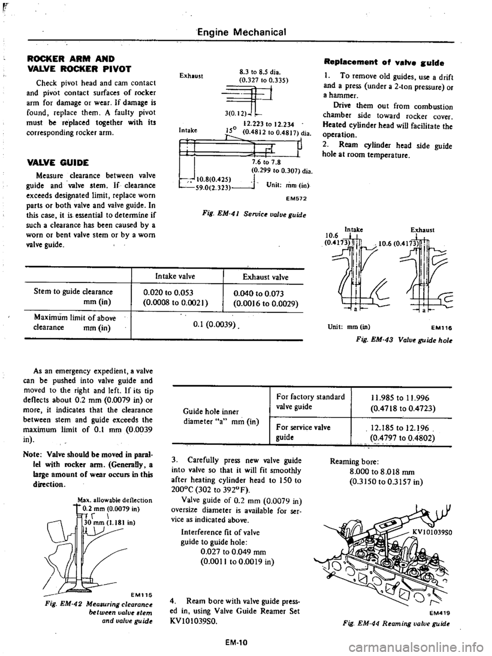
ROCKER
ARM
AND
VALVE
ROCKER
PIVOT
Check
pivot
head
and
cam
contact
and
pivot
contact
surfaces
of
rocker
arm
for
damage
or
wear
If
damage
is
found
replace
them
A
faulty
pivot
must
be
replaced
together
with
its
corresponding
rocker
arm
VALVE
GUIDE
Measure
clearance
between
valve
guide
and
valve
stem
If
clearance
exceeds
designated
limit
replace
worn
parts
or
both
valve
and
valve
guide
In
this
case
it
is
essential
to
determine
if
such
a
clearance
has
been
caused
by
a
worn
or
bent
valve
stem
or
by
a
worn
valve
guide
Stem
to
guide
clearance
mm
in
Maximum
limit
of
above
clearance
mm
in
Engine
Mechanical
Exhaust
8
3
to
8
5
dia
0
327
to
0
335
4
1
3
0
I2
J
L
12
223
to
12
234
150
0
4812
to
0
4817
dia
1
P
Intake
I
I
J
10
8
0
425
S9
0
2
323
7
6
to
7
8
0
299
to
0
307
dia
1
Unit
mm
in
EM572
Fig
EM
41
Se11Jice
value
guide
In
take
valve
Exhaust
valve
0
020
to
0
053
0
0008
to
0
002
As
an
emergency
expedient
a
valve
can
be
pushed
into
valve
guide
and
moved
to
the
right
and
left
If
its
tip
deflects
about
0
2
mm
0
0079
in
or
more
it
indicates
that
the
clearance
between
stem
and
guide
exceeds
the
maximum
limit
of
0
1
mm
0
0039
in
Note
Valve
should
be
moved
in
paral
lel
with
rocker
arm
Generally
a
large
amount
of
wear
occurs
in
this
direction
Max
allowable
deflection
0
2
mm
0
0079
in
n
r
C1r
30mm
l
18Iin
r
EM115
Fig
EM
42
Mea
uring
clearance
between
valve
tern
and
valve
gu
ide
0
040
to
0
073
0
00
6
to
0
0029
0
1
0
0039
Replacement
of
valve
guide
I
To
remove
old
guides
use
a
drift
and
a
press
under
a
2
ton
pressure
or
a
hammer
Drive
them
out
from
combustion
chamber
side
toward
rocker
cover
Heated
cylinder
head
will
facilitate
the
operation
2
Ream
cylinder
head
side
guide
hole
at
room
temperature
10
6
E
e
417
5t
0
m3l
lj
10
6
O
fl
H
dl7
l
IV
II
Unit
mm
in
EM116
Fig
EM
43
Valve
guide
hole
Guide
hole
inner
diameter
an
mm
in
For
factory
standard
valve
guide
11
985
to
11
996
0
4718
to
0
4723
For
service
valve
guide
3
Carefully
press
new
valve
guide
into
valve
so
that
it
will
fit
smoothly
after
heating
cylinder
head
to
150
to
2000C
302
to
3920
F
Valve
guide
of
0
2
mm
0
0079
in
oversize
diameter
is
available
for
ser
vice
as
indicated
above
Interference
fit
of
valve
guide
to
guide
hole
0
027
to
0
049
mm
0
0011
to
0
0019
in
4
Ream
bore
with
valve
guide
press
ed
in
using
Valve
Guide
Reamer
Set
KVIOI039S0
EM
10
12
185
to
12
96
0
4797
to
0
4802
Reaming
bore
8
000
to
8
018
rnm
0
3150
to
0
3157
in
EM419
Fig
EM
44
Reaming
valve
guide
Page 58 of 537
Standard
Camshaft
bend
mm
in
0
02
0
0008
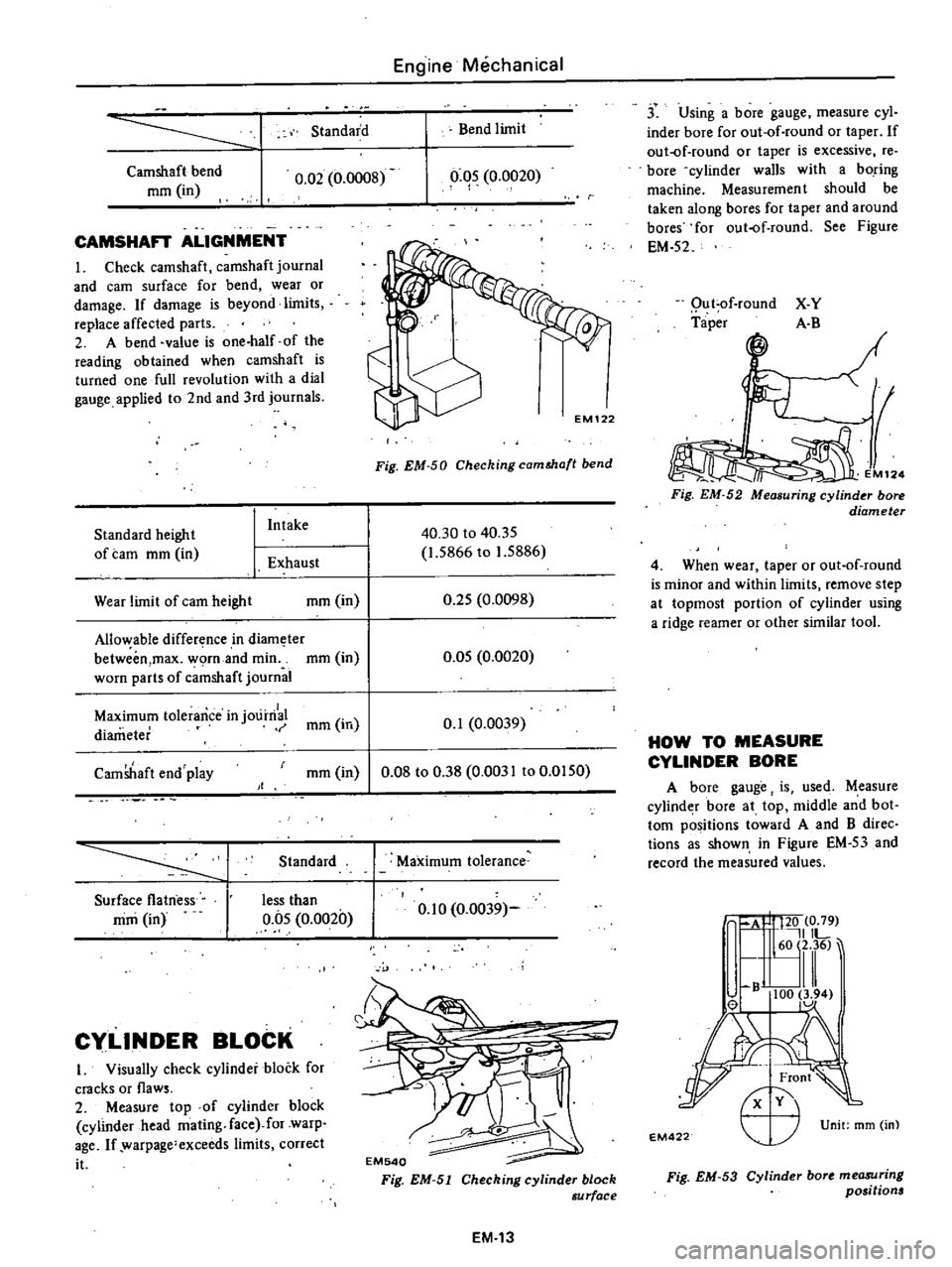
CAMSHAFT
ALIGNMENT
I
Check
camshaft
camshaft
journal
and
earn
surface
for
bend
wear
or
damage
If
damage
is
beyond
limits
replace
affected
parts
2
A
bend
value
is
one
half
of
the
reading
obtained
when
camshaft
is
turned
one
full
revolution
with
a
dial
gauge
applied
to
2nd
and
3rd
journals
Standard
height
of
tam
mm
in
I
Intake
1
Exhaust
Wear
limit
of
earn
height
mm
in
Allo
able
difference
in
diam
ter
betweim
max
worn
and
min
mm
in
worn
parts
of
c
mshaft
journal
Engine
Mechanical
Bend
limit
0
05
0
0020
I
Fig
EM
50
Checking
camMa
t
bend
40
30
to
40
35
1
5866
to
1
5886
0
25
0
0098
0
05
0
0020
Maximum
tolerance
in
j01
irri
mm
in
0
1
0
0039
diameter
CamShaft
end
play
mm
in
0
08
to
0
38
0
0031
to
0
0150
Standard
Surface
flatness
mm
in
less
than
0
05
0
0020
Cy
LlNDER
BLOCK
I
Visually
check
cylinder
block
for
cracks
or
flaws
2
Measure
top
of
cylinder
block
cylinder
head
mating
face
for
warp
age
If
warpage
exceeds
limits
correct
it
Maximum
tolerance
0
10
0
0039
EM540
Fig
EM
51
Cheching
cylinder
block
au
rface
EM
13
j
Using
a
bore
gauge
measure
cyl
inder
bore
for
out
of
round
or
taper
If
out
of
round
or
taper
is
excessive
re
bore
cylinder
walls
with
a
boring
machine
Measuremen
t
should
be
taken
along
bores
for
taper
and
around
bores
for
out
of
round
See
Figure
EM
52
Qu
t
of
round
Taper
X
Y
A
B
M12
Fig
EM
52
Measuring
cylinder
bore
diameter
4
When
wear
taper
or
out
of
round
is
minor
and
within
limits
remove
step
at
topmost
portion
of
cylinder
using
a
ridge
reamer
or
other
similar
tool
HOW
TO
MEASURE
CYLINDER
BORE
A
bore
gauge
is
used
Measure
cylind
r
bore
at
top
middle
and
bot
tom
positions
toward
A
and
B
direc
tions
as
shown
in
Figure
EM
53
and
record
the
measured
values
A
I
120
0
79
IlL
60
2
36
lll
B
100
3
94
el
1
Unit
mm
m
EM
22
r
Fig
EM
53
Cylinder
bort
me08Uring
positions
Page 66 of 537
PRECAUTIONS
CYLINDER
HEAD
PRECAUTIONS
I
Use
thoroughly
cleaned
parts
Especially
make
sure
that
oil
holes
are
clear
of
foreign
matter
2
When
installing
sliding
parts
such
as
bearings
be
s
uIe
to
apply
engine
oil
to
them
3
Use
new
packing
and
oil
seals
4
Do
not
reuse
lock
washers
5
Keep
tools
and
work
benches
clean
6
Keep
necessary
parts
and
tools
near
at
hand
7
Be
sure
to
follow
specified
tight
ening
torque
and
order
8
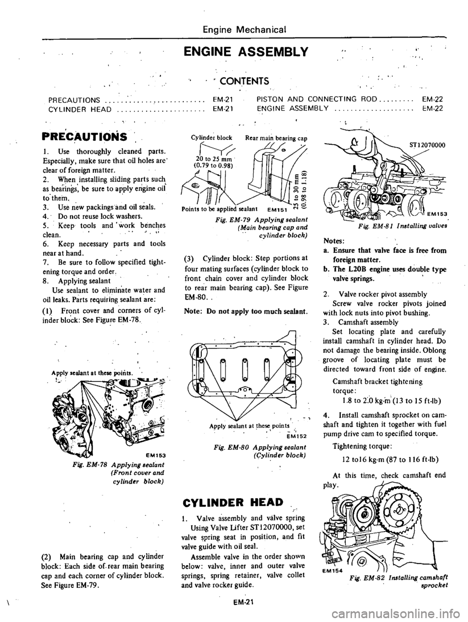
Applying
sealant
Use
sealant
to
eliminate
water
and
oil
leaks
Parts
requiring
sealant
are
I
Front
cover
and
corners
of
cyl
inder
block
See
Figure
EM
78
EM153
Fig
EM
78
Applying
alant
Front
cover
and
cylinder
block
2
Main
bearing
cap
and
cylinder
block
Each
side
of
rear
main
bearing
cap
and
each
corner
of
cylinder
block
See
Figure
EM
79
Engine
Mechanical
ENGINE
ASSEMBLY
CONTENTS
EM
21
EM
21
PISTON
AND
CONNECTING
ROD
ENGINE
ASSEMBLY
EM
22
EM
22
Cylinder
block
Rear
main
bearing
cap
20to2Smm
Ill
Points
to
be
applied
sealant
EM151
s
e
00
000
o
Fig
EM
79
Applying
sealanl
Main
bearing
cap
and
cylinder
block
3
Cylinder
block
Step
portions
at
four
mating
surfaces
cylinder
block
to
front
chain
cover
and
cylinder
block
to
rear
main
bearing
cap
See
Figure
EM
80
Note
Do
not
apply
too
much
sealant
J
Apply
sealant
at
hese
points
EM152
Fig
EM
80
Applying
sealant
Cylinder
block
CYLINDER
HEAD
Valve
assembly
and
valve
spring
Using
Valve
Lifter
STl2070000
set
valve
pring
seat
in
position
and
fit
valve
guide
with
oil
seaL
Assemble
valve
in
the
order
shown
below
valve
inner
and
outer
valve
springs
spring
retainer
valve
collet
and
valve
rocker
guide
EM
21
Fig
EM
81
Installing
valves
Notes
a
Ensure
that
valve
face
is
free
from
foreign
matter
b
The
L20B
engine
uses
double
type
valve
springs
2
Valve
rocker
pivot
assembly
Screw
valve
rocker
pivots
joined
with
lock
nuts
into
pivot
hushing
3
Camshaft
assembly
Set
locating
plate
and
carefully
install
camshaft
in
cylinder
head
Do
not
damage
the
bearing
inside
Oblong
groove
of
locating
plate
must
be
directed
toward
front
side
of
engine
Camshaft
bracket
tightening
torque
1
8
to
2
0
kg
in
13
to
15
ft
lb
4
Install
camshaft
sprocket
on
earn
shaft
and
tighten
it
together
with
fuel
pump
drive
cam
to
specified
torque
Tightening
torque
12
tol6
kg
m
87
to
116
ft
lb
this
time
check
camshaft
end
Fig
EM
82
Installing
camshaft
sprocket
Page 67 of 537
5
Install
rocker
arms
by
pressing
valve
springs
down
with
a
screwdriver
6
Install
valve
rocker
springs
7
After
assembling
cylinder
head
turn
camshaft
until
No
I
piston
is
at
T
D
C
on
its
compression
stroke
EM1S5
Fig
EM
83
A
embling
cylinder
head
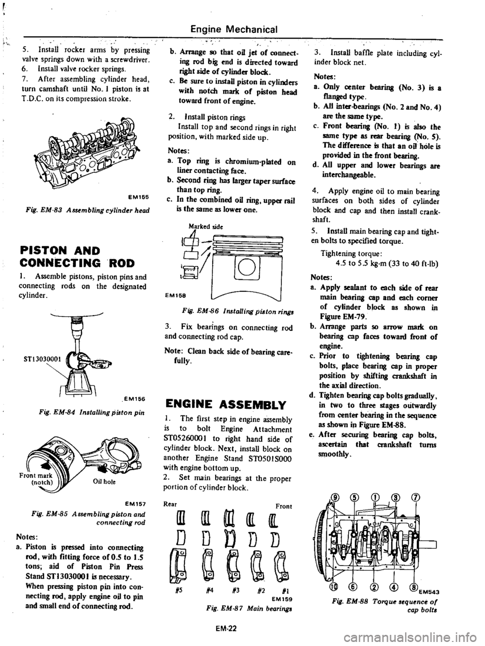
PISTON
AND
CONNECTINGROD
1
Assemble
pistons
piston
pins
and
connecting
rods
on
the
de
ignated
cylinder
STl3030001
EM156
Fig
EM
84
Installing
piston
pin
EM157
Fig
EM
85
Assembling
piston
and
connecting
rod
Notes
a
Piston
is
pressed
into
connecting
rod
with
fitting
force
of
0
5
to
5
tons
aid
of
Piston
Pin
Press
Stand
STl303000
I
is
necessary
When
pressing
piston
pin
into
con
necting
rod
apply
engine
oil
to
pin
and
small
end
of
connecting
rod
Engine
Mechanical
b
Arrange
so
that
oil
jet
of
connect
ing
rod
big
end
is
directed
toward
right
side
of
eylinder
block
c
Be
sure
to
install
piston
in
cylinders
with
notch
mark
of
piston
head
toward
front
of
engine
2
Install
piston
rings
InstalI
top
and
second
rings
in
right
position
with
marked
side
up
Notes
a
Top
ring
is
chromium
plated
on
liner
contacting
face
b
Second
ring
has
larger
taper
surface
than
top
ring
c
In
the
combined
oil
ring
upper
rail
is
the
same
as
lower
one
j
c6J
EM158
Fig
EM
86
lalling
pidon
rings
3
Fix
bearings
on
connecting
rod
and
connecting
rod
cap
Note
Clean
back
side
of
bearing
care
fully
ENGINE
ASSEMBLY
The
first
step
in
engine
assembly
is
to
bolt
Engine
Attachment
ST0526000
I
to
right
hand
ide
of
cylinder
block
Next
install
block
on
another
Engine
Stand
ST0501S000
with
engine
bottom
up
2
Set
main
bearings
at
the
proper
portion
of
cylinder
block
Rear
Front
III
III
m
It
IlL
D
D
D
D
D
1
5
1
4
1
3
1
2
1
1
EM159
Fig
EM
87
Main
bearings
EM
22
3
Install
baffle
plate
including
cyl
inder
block
net
Notes
a
Only
center
bearing
No
3
is
a
flanged
type
b
All
inter
bearings
No
2
and
No
4
are
the
same
type
c
Front
bearing
No
I
is
also
the
same
type
as
rear
bearing
No
5
The
difference
is
that
an
oil
hole
is
provided
in
the
front
bearing
d
All
upper
and
lower
bearings
are
interchangeable
4
Apply
engine
oil
to
main
bearing
surfaces
on
both
sides
of
cylinder
block
and
cap
and
then
install
crank
shaft
5
Install
main
bearing
cap
and
tight
en
bolts
to
specified
torque
Tightening
torque
4
5
to
5
5
kg
m
33
to
40
ft
lb
Notes
a
Apply
sealant
to
each
side
of
rear
main
bearing
cap
and
each
comer
of
eylinder
block
as
shown
in
Figure
EM
79
b
Arrange
parts
so
arrow
mark
on
bearing
cap
faces
toward
front
of
engine
c
Prior
to
tightening
bearing
cap
bolts
place
bearing
cap
in
proper
position
by
shifting
crankshaft
in
the
axial
direction
d
Tighten
bearing
cap
bolts
gradually
in
two
to
three
stages
outwardly
from
center
bearing
in
the
sequence
as
shown
in
Figure
EM
88
e
After
securing
bearing
cap
bolts
ascertain
that
aankshaft
turns
smoothly
@
i
d
l
j
1
@EM543
Fig
EM
8S
Torque
sequence
0
cap
bolt
Page 70 of 537
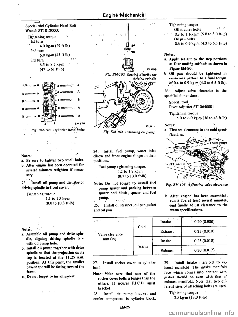
Speci
ol
Cylinder
Head
Bolt
Wren
h
8110120000
Tightening
torque
1st
turn
4
0
kg
m
29
ft
lb
2nd
turn
6
0
kg
m
43
ft
lb
3rd
turn
6
5
to
8
5
kg
m
47
to
61
ft
lb
B
O
A
A
B
A
A
B
O
B
O
R
O
EM
176
Fig
EM
I02
Cylinder
head
boll
Notes
a
Be
sure
to
tighten
two
small
bolts
b
After
engine
has
been
operated
for
several
minutes
retighten
if
neces
sary
23
Install
oil
pump
and
distr
butor
driving
spindle
in
front
cover
Tightening
torque
1
1
to
1
5
kg
m
8
0
to
10
8
ft
lb
Notes
a
Assemble
oil
pump
and
drive
spin
die
aligning
driving
spindle
face
with
oil
pump
hole
b
Install
oil
pump
together
with
drive
spindle
so
that
the
projection
on
its
top
is
located
at
the
II
25
a
m
position
At
this
point
the
smaller
bow
shape
will
be
facing
toward
the
front
c
Do
not
forget
to
install
gas
et
Engine
Mechanical
I
Fig
EM
I04
11l6lalling
oil
pump
24
Install
fuel
pump
water
inlet
elbow
and
front
engine
slinger
in
their
positions
Fuel
pump
tightening
torque
1
2
to
1
8
kg
m
8
7
to
13
0
ft
lb
Note
Do
not
forget
to
install
fuel
pump
spacer
and
packing
between
spacer
and
block
spacer
and
fuel
pump
25
Install
oil
strainer
oil
pan
gasket
and
oil
pan
27
Install
rocker
cover
to
cylinder
head
Note
Make
sure
that
one
of
the
rocker
cover
bolts
is
longer
than
the
others
It
secures
F
I
C
D
assist
bracket
28
Install
air
pump
bracket
and
cooler
compressor
to
cylinder
block
EM
25
Tightening
torque
Oil
strainer
bolts
0
8
to
I
l
kg
m
5
8
to
8
0
ft
lb
Oil
pan
bolts
0
6
to
0
9
kg
m
4
3
to
6
5
ft
lb
Notes
a
Apply
sealant
to
the
step
portions
at
four
mating
surfaces
as
shown
in
Figure
EM
80
b
Oil
pan
should
be
tigh
tened
in
criss
cross
pattern
to
a
final
torque
of
0
6
to
0
9
kg
m
4
3
to
6
5
ft
lb
26
Adjust
valve
clearance
to
the
specified
dimensions
Special
tool
Pivot
Adj
iier
STl064000l
Tightening
torque
5
0
to
6
0
kg
m
36
to
43
ft
lb
Fig
EM
I05
Adjusting
valve
clearance
b
After
engine
has
been
assembled
run
it
for
at
least
several
minutes
and
finally
adjust
clearance
to
the
warm
specifications
29
Install
intake
manifold
to
ex
haust
manifold
The
intake
manifold
face
which
comes
into
contact
with
gasket
should
be
even
with
that
of
exhaust
manifold
Note
that
two
dif
ferent
sizes
of
attaching
bolts
are
used
Tightening
torque
2
5
kg
m
18
0
ft
lb
Page 86 of 537
ENGINE
LUBRICATION
SYSTEM
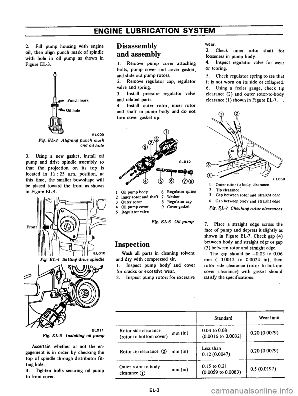
2
Fill
pump
housing
with
engine
oil
then
align
punch
mark
of
spindle
with
hole
in
oil
pump
as
shown
in
Figure
EL
3
Punch
mark
EL009
Fig
EL
3
Aligning
punch
mark
and
oil
hole
3
Using
a
new
gasket
install
oil
pump
and
drive
spindle
assembly
so
that
the
projection
on
its
top
is
located
in
II
25
a
m
position
at
this
time
the
smaller
bow
shape
will
be
placed
toward
the
front
as
shown
in
Figure
EL
4
JI
I
c
J
V
Front
J
@
9@
tr
i
d
L
It
I
I
EL010
Fig
EL
4
Setting
drive
pindle
o
EL011
Fig
EL
5
Imtalling
oil
pump
Ascertain
whether
or
not
the
en
gagement
is
in
order
by
checking
the
top
of
spindle
through
distributor
fit
ting
hole
4
Tighten
bolts
securing
oil
pump
to
front
cover
Disassembly
and
assembly
I
Remove
pump
cover
attaching
bolts
pump
cover
and
cover
gasket
and
slide
out
pump
rotors
2
Remove
regulator
cap
regulator
valve
and
spring
3
Install
pressure
regulator
valve
and
related
parts
4
Install
outer
rotor
inner
rotor
and
shaft
in
pump
body
and
do
not
turn
cover
gasket
up
CD
El012
r
@
@
CD@
1
Oil
pump
body
2
Inner
rotor
and
shaft
3
Outer
rotor
4
Oil
pump
cover
5
Regulator
valve
6
Regulator
spring
7
Washer
8
Regulator
cap
9
Cover
gasket
Fig
EL
6
Oil
pump
Inspection
Wash
all
parts
in
cleaning
solvent
and
dry
with
compressed
ir
I
Inspect
pump
body
and
cover
for
cracks
or
excessive
wear
2
Inspect
pump
rotors
for
excessive
Rotor
side
clearance
rotor
to
bottom
cover
Olm
in
Rotor
tip
clearance
@
mOl
in
Outer
rotor
to
body
clearance
D
mm
inl
EL
3
wear
3
Check
inner
rotor
shaft
for
looseness
in
pump
body
4
Inspect
regulator
valve
for
wear
or
scoring
5
Check
regulator
spring
to
see
that
it
is
not
worn
on
its
side
or
collapsed
6
Using
a
feeler
gauge
check
tip
clearance
2
and
outer
rotor
to
body
clearance
I
shown
in
Figure
EL
7
1
Outer
rotor
to
body
clearance
2
Tip
clearance
3
Gap
between
rotor
and
straight
edge
4
Gap
between
body
and
straight
edg
e
Fig
EL
7
Checking
rotor
clearance
7
Place
a
straight
edge
across
the
face
of
pump
and
depress
it
slightly
as
shown
in
Figure
EL
7
Check
gap
4
between
body
and
straight
edge
or
gap
3
between
rotor
and
straight
edge
The
gap
should
be
0
03
to
0
06
mm
0
0012
to
0
0024
in
then
rotor
side
clearance
rotor
to
bottom
cover
clearance
with
gasket
should
satisfy
the
specifications
Standard
Wear
limit
0
04
to
0
08
0
0016
to
0
0032
0
20
0
0079
Less
than
0
12
0
0047
0
20
0
0079
0
15
to
0
21
0
0059
to
0
0083
0
5
0
0197