radio DATSUN PICK-UP 1977 Service Manual
[x] Cancel search | Manufacturer: DATSUN, Model Year: 1977, Model line: PICK-UP, Model: DATSUN PICK-UP 1977Pages: 537, PDF Size: 35.48 MB
Page 157 of 537
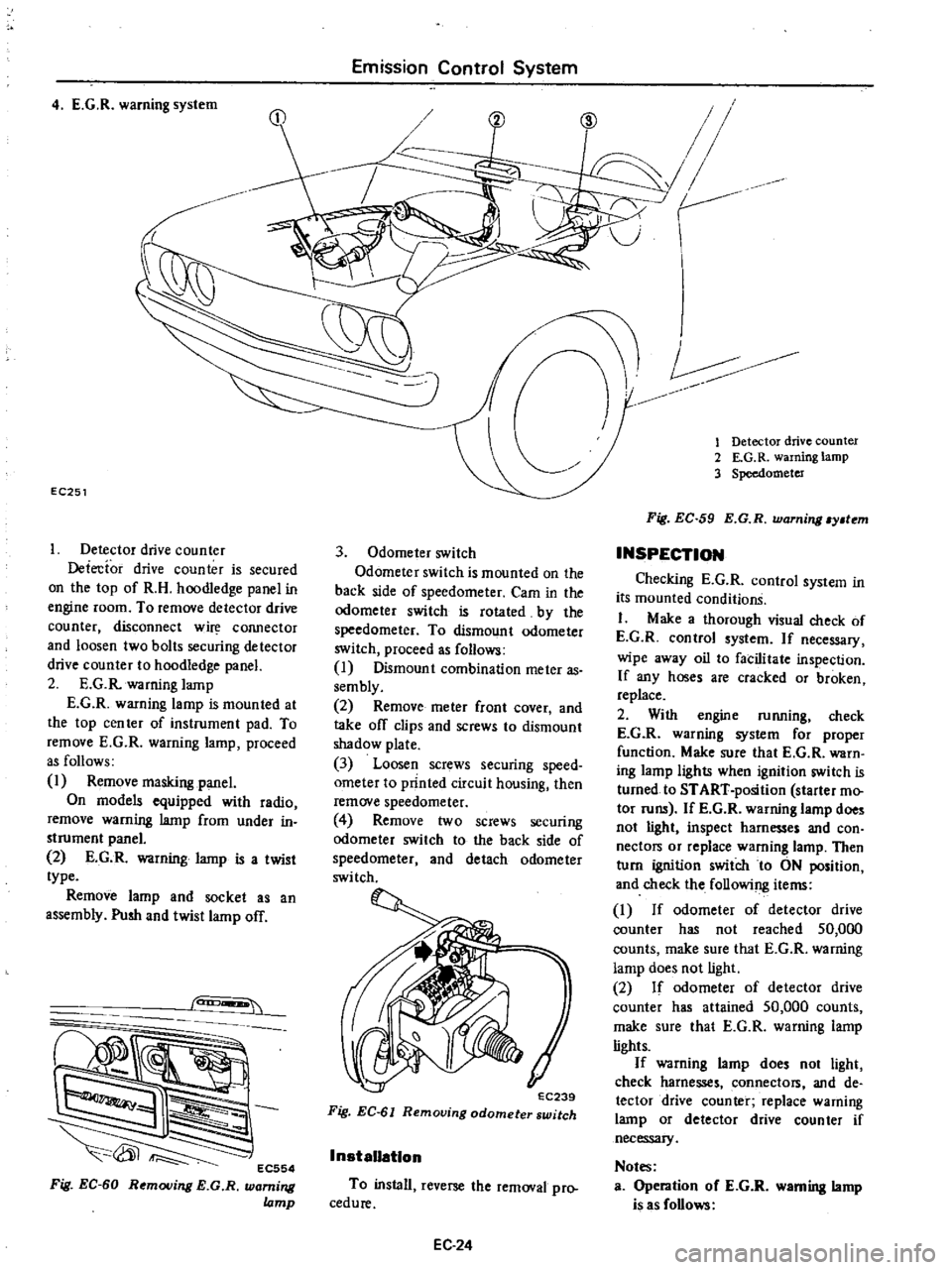
4
E
G
R
warning
system
EC251
Detector
drive
counter
Detecfor
drive
counter
is
secured
on
the
top
of
R
H
hoodledge
panel
in
engine
room
To
remove
detector
drive
counter
disconnect
w
COJUlector
and
loosen
two
bolts
securing
detector
drive
counter
to
hoodledge
panel
2
E
G
R
warning
lamp
E
G
R
warning
lamp
is
mounted
at
the
top
cen
ter
of
instrument
pad
To
remove
E
G
R
warning
lamp
proceed
as
follows
1
Remove
masking
panel
On
models
equipped
with
radio
remove
warning
lamp
from
under
in
strument
panel
2
E
G
R
warning
lamp
is
a
twist
type
Remove
lamp
and
socket
as
an
assembly
Push
and
twist
lamp
off
can
EC554
Fig
EC
60
Removing
E
G
R
warning
lamp
Emission
Control
System
3
Odometer
switch
Odometer
switch
is
mounted
on
the
back
side
of
speedometer
Cam
in
the
odometer
switch
is
rotated
by
the
speedometer
To
dismount
odometer
switch
proceed
as
follows
I
Dismount
combination
meter
as
sembly
2
Remove
meter
front
cover
and
take
off
clips
and
screws
to
dismount
shadow
plate
3
Loosen
screws
securing
speed
ometer
to
printed
circuit
housing
then
remove
speedometer
4
Remove
two
screws
securing
odomete
switch
to
the
back
side
of
speedometer
and
detach
odometer
switch
EC239
Fig
EC
61
Removing
odometer
switch
InstaUatlon
To
install
reverse
the
removal
pro
cedure
EC24
V
r
CID
1
Detector
drive
counter
2
E
G
R
warning
lamp
3
Speedometer
Fig
EC
59
E
G
R
warning
y
tem
INSPECTION
Checking
E
G
R
control
system
in
its
mounted
conditionS
I
Make
a
thorough
visual
check
of
E
G
R
control
system
If
necessary
wipe
away
oil
to
facilitate
inspection
If
any
hoses
are
cracked
or
broken
replace
2
With
engine
running
check
E
G
R
warning
system
for
proper
function
Make
sure
that
E
G
R
warn
ing
lamp
lights
when
ignition
switch
is
turned
to
START
position
starter
mo
tor
runs
If
E
G
R
wanung
lamp
does
not
light
inspect
harnesses
and
con
nectors
or
replace
warning
lamp
Then
turn
ignition
switch
to
ON
position
and
check
the
following
items
I
If
odometer
of
detector
drive
counter
has
not
reached
50
000
counts
make
sure
that
E
G
R
warning
lamp
does
not
light
2
If
odomete
of
detector
drive
counter
has
attained
50
000
counts
make
sure
that
E
G
R
warning
lamp
lights
If
warning
lamp
does
not
light
check
harnesses
connectors
and
de
tector
drive
counter
replace
warning
lamp
or
detector
drive
counter
if
necessary
Notes
Operation
oC
E
G
R
warning
lamp
is
as
Collows
Page 188 of 537
MEASUREMENT
OF
REGULATOR
VOLTAGE
Regulator
voltage
is
measured
with
regulator
assembled
with
alternator
When
measuring
voltage
with
regulator
mounted
on
car
it
is
necessary
to
rotate
engine
at
high
speed
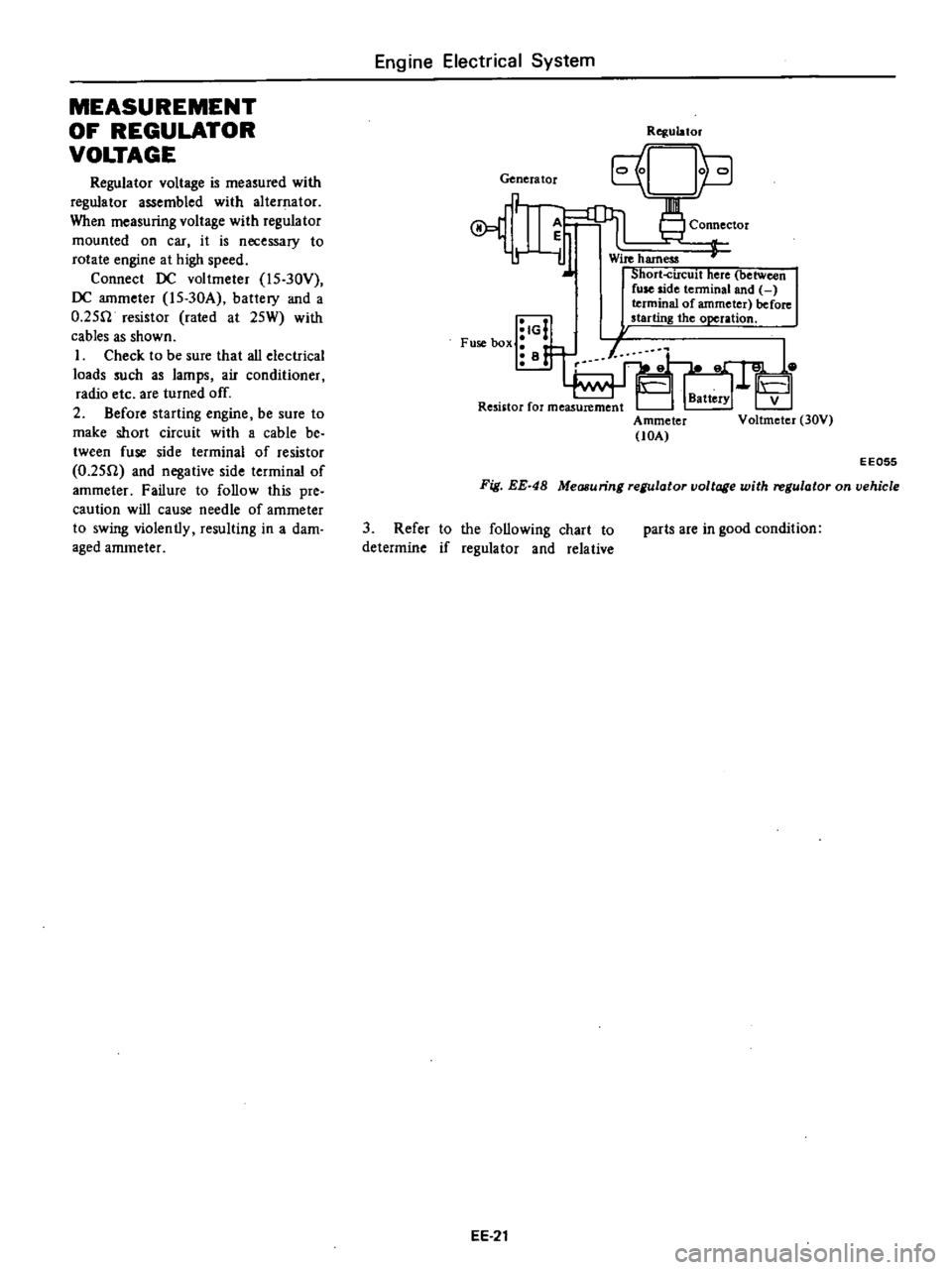
Connect
DC
voltmeter
l5
30Y
DC
ammeter
l5
30A
battery
and
a
O
25fl
resistor
rated
at
25W
with
cables
as
shown
I
Check
to
be
sure
that
all
electrical
loads
such
as
lamps
air
conditioner
radio
etc
are
turned
off
2
Before
starting
engine
be
sure
to
make
short
circuit
with
a
cable
be
tween
fuse
side
terminal
of
resistor
O
25fl
and
negative
side
terminal
of
ammeter
Failure
to
follow
this
pre
caution
will
cause
needle
of
ammeter
to
swing
violently
resulting
in
a
dam
aged
ammeter
Engine
Electrical
System
Genera
tor
A
r
iJ
IG
Fuse
box
i
B
Rqulator
Connector
Wire
harness
Short
circuit
here
between
fuse
side
tenninal
and
terminal
of
ammeter
before
starting
the
operation
Ammeter
lOA
V
Voltmeter
30V
EE055
Fig
EE
48
Measuring
regulator
voltage
with
regulator
on
vehicle
3
Refer
to
the
following
chart
to
determine
if
regulator
and
relative
EE
21
parts
are
in
good
condition
Page 466 of 537
Body
Electrical
System
ELECTRICAL
ACCESSORIES
CONTENTS
HORN
DESCRIPTION
REMOVAL
AND
INSTALLATION
IGNITION
SWITCH
REMOVAL
AND
INSTALLATION
INSPECTION
WINDSHIELD
WIPER
AND
WASHER
REMOVAL
AND
INSTALLATION
INSPECTION
RADIO
REMOVAL
AND
INSTALLATION
ADJUSTMENT
CLOCK
REMOVAL
I
NST
ALLA
TION
HEATER
DESCRIPTION
AIRFLOW
HEATER
UNIT
ASSEMBLY
BE
21
BE
21
BE
21
8E
n
BE
22
BE
22
BE
23
BE
23
BE
23
BE
25
BE
25
BE
25
BE
25
BE
25
BE
26
BE
26
BE
26
BE
28
BE
29
HORN
DESCRIPTION
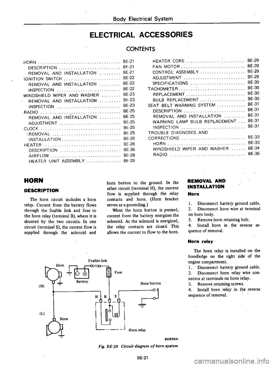
The
horn
circuit
includes
a
horn
relay
Current
from
the
battery
flows
through
the
fusible
link
and
fuse
to
the
horn
relay
terminal
B
where
it
is
shunted
by
the
two
circuits
In
one
circuit
terminal
S
the
current
flow
is
supplied
through
the
solenoid
and
Fusible
link
Qi
att
Fu
H
I
HIBQ
t
J
JJI
L
J
Hornrelay
Qm
HEATER
CORE
FAN
MOTOR
CONTROL
ASSEMBLY
ADJUSTMENT
SPECIFICATIONS
TACHOMETER
REPLACEMENT
8UL8
REPLACEMENT
SEAT
8ELT
WARNING
SYSTEM
DESCRIPTION
REMOVAL
AND
INSTALLATION
WARNING
LAMP
BULB
REPLACEMENT
INSPECTION
TROUBLE
DIAGNOSES
AND
CORRECTIONS
HORN
WINDSHIELD
WIPER
AND
WASHER
RADIO
Horn
button
BE859A
Fig
BE
29
Circuit
diagram
of
horn
sy
tem
horn
button
to
the
ground
In
the
other
circuit
terminal
H
the
current
flow
is
supplied
through
the
relay
contacts
and
horn
Horn
bracket
serves
as
a
grounding
When
the
horn
button
is
pressed
current
from
the
battery
energizes
the
solenoid
As
the
solenoid
is
energized
the
relay
contacts
are
closed
This
allows
the
current
to
flow
to
the
horn
BE
21
REMOVAL
AND
INSTALLATION
Horn
8E
29
BE
29
BE
29
8E
29
BE
30
BE
30
BE
30
8E
30
8E
31
BE
31
BE
31
8E
31
8E
31
BE
33
8E
33
8E
34
BE
35
I
Disconnect
battery
ground
cable
2
Disconnect
horn
wire
at
terminal
on
horn
body
3
Remove
horn
retaining
bolt
4
Install
horn
in
the
reverse
se
quence
of
removal
Horn
relay
The
horn
relay
is
installed
on
the
hoodIedge
on
the
right
side
of
the
engine
compartment
I
Disconnect
battery
ground
cable
2
Disconnect
horn
relay
wire
con
nector
at
terminals
on
horn
relay
3
Remove
retaining
screws
4
Install
horn
relay
in
the
reverse
sequence
of
removal
Page 470 of 537
RADIO
REMOVAL
AND
INSTALLATION
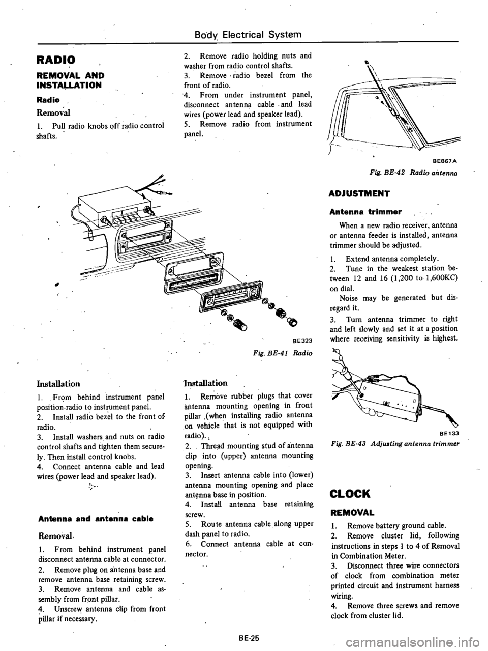
Radio
Removal
Pull
radio
knobs
offradio
control
shafts
Body
Electrical
System
2
Remove
radio
holding
nuts
and
washer
from
radio
control
shafts
3
Remove
radio
bezel
from
the
front
of
radio
4
From
under
instrument
panel
disconnect
antenna
cable
and
lead
wires
power
lead
and
speaker
lead
5
Remove
radio
from
instrument
panel
Installation
Fr
m
behind
instrument
panel
position
radio
to
instrument
panel
2
Install
radio
bezel
to
the
front
of
radio
3
Install
washers
and
nuts
on
radio
control
shafts
and
tighten
them
secure
ly
Then
install
control
knobs
4
Connect
antenna
cable
and
lead
wires
power
lead
and
speaker
lead
Antenna
and
antenna
cable
Removal
From
behind
instrument
panel
disconnect
antenna
cable
at
conne
tor
2
Remove
plug
on
antenna
base
and
remove
antenna
base
retaining
screw
3
Remove
antenna
and
cable
as
sembly
from
fr
ont
pillar
4
Unscrew
antenna
clip
from
front
pillar
if
necessary
aE323
Fig
BE
41
Radio
Installation
Remove
rubber
plugs
that
cover
antenna
mounting
opening
in
front
pillar
when
installing
radio
antenna
on
vehicle
that
is
not
equipped
with
radio
2
Thread
mounting
stud
of
antenna
clip
into
upper
antenna
mountins
opening
3
Insert
antenna
cable
into
lower
antenna
mounting
opening
and
place
ant
nna
base
in
position
4
Install
antenna
base
retaining
screw
5
Route
antenna
cable
along
upper
dash
panel
to
radio
6
Connect
antenna
cable
at
con
nector
BE
25
t
BEB67
A
Fig
BE
42
Radio
ant
nna
ADJUSTMENT
Antenna
trimmer
When
a
new
radio
receiver
antenna
or
antenna
feeder
is
installed
antenna
trimmer
should
be
adjusted
Extend
antenna
completely
2
Tune
in
the
weakest
station
be
tween
12
and
16
1
200
to
1
600KC
on
dial
Noise
may
be
generated
but
dis
regard
it
3
Turn
antenna
trimmer
to
right
and
left
slowly
and
set
it
at
a
position
where
receiving
sensitivity
is
highest
SE133
Fig
BE
43
Adjwting
antenna
trimmer
CLOCK
REMOVAL
Remove
battery
ground
cable
2
Remove
cluster
lid
following
instructions
in
steps
I
to
4
of
Removal
in
Combination
Meter
3
Disconnect
three
wire
connectors
of
clock
from
combination
meter
printed
circuit
and
instrument
harnes
wiring
4
Remove
three
s
rews
and
remove
clock
from
cluster
lid
Page 474 of 537
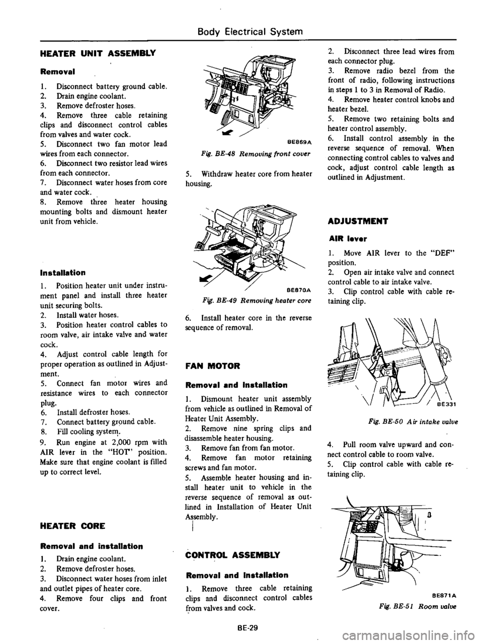
HEATER
UNIT
ASSEMBLY
Removal
L
Disconnect
battery
ground
cable
2
Drain
engine
coolant
3
Remove
defroster
hoses
4
Remove
three
cable
retaining
clips
and
disconnect
control
cables
from
valves
and
water
cock
5
Disconnect
two
fan
motor
lead
wires
from
each
connector
6
Disconnect
two
resistor
lead
wires
from
each
connector
7
Disconnect
water
hoses
from
core
and
water
cock
8
Remove
three
heater
housing
mounting
bolts
and
dismount
heater
unit
from
vehicle
Installation
1
Position
heater
unit
under
instru
ment
panel
and
install
three
heater
unit
securing
bolts
2
Install
water
hoses
3
Position
heater
control
cables
to
room
valve
air
intake
valve
and
water
cock
4
Adjust
control
cable
length
for
proper
operation
as
outlined
in
Adjust
ment
5
Connect
fan
motor
wires
and
resistance
wires
to
each
connector
plug
6
Install
defroster
hoses
7
Connect
battery
ground
cable
8
Fill
cooling
systeIT
9
Run
engine
at
2
000
rpm
with
AIR
lever
in
the
HOT
position
Make
sure
that
engine
coolant
is
fIlled
up
to
correct
level
HEATER
CORE
Removal
and
installation
L
Drain
engine
coolant
2
Remove
defroster
hoses
3
Disconnect
water
hoses
from
inlet
and
outlet
pipes
of
heater
core
4
Remove
four
clips
and
front
cover
Body
Electrical
System
BE869A
Fig
BE
48
Removing
front
cov
r
S
Withdraw
heater
core
from
heater
housing
BE870A
Fig
BE
49
Removing
heater
core
6
Install
heater
core
in
the
reverse
sequence
of
removal
FAN
MOTOR
Removal
and
Installation
L
Dismount
heater
unit
assembly
from
vehicle
as
outlined
in
Removal
of
Heater
Unit
Assembly
2
Remove
nine
spring
clips
and
disassemble
heater
housing
3
Remove
fan
from
fan
motor
4
Remove
fan
motor
retaining
screws
and
fan
motor
S
Assemble
heater
housing
and
in
stall
heater
unit
to
vehicle
in
the
reverse
sequence
of
removal
as
out
lined
in
Installation
of
Heater
Unit
Assembly
I
CONTROL
ASSEMBLY
Removal
and
Installation
I
Remove
three
cable
retaining
clips
and
disconnect
control
cables
from
valves
and
cock
BE
29
2
Disconnect
three
lead
wires
from
each
connector
plug
3
Remove
radio
bezel
from
the
front
of
radio
following
instructions
in
steps
I
to
3
in
Removal
of
Radio
4
Remove
heater
control
knobs
and
heater
bezel
5
Remove
two
retaining
bolts
and
heater
control
assembly
6
Install
control
assembly
in
the
reverse
sequence
of
removal
When
connecting
control
cables
to
valves
and
cock
adjust
control
cable
length
as
outlined
in
Adjustment
ADJUSTMENT
AIR
lever
L
Move
AIR
lever
to
the
DEF
position
2
Open
air
intake
valve
and
connect
control
cable
to
air
intake
valve
3
Clip
control
cable
with
cable
re
taining
clip
Fig
BE
50
A
iT
intake
valve
4
Pull
room
valve
upward
and
con
nect
control
cable
to
room
valve
5
Clip
control
cable
with
cable
re
taining
clip
BE871A
Fig
BE
51
Room
valve
Page 480 of 537
Body
Electrical
System
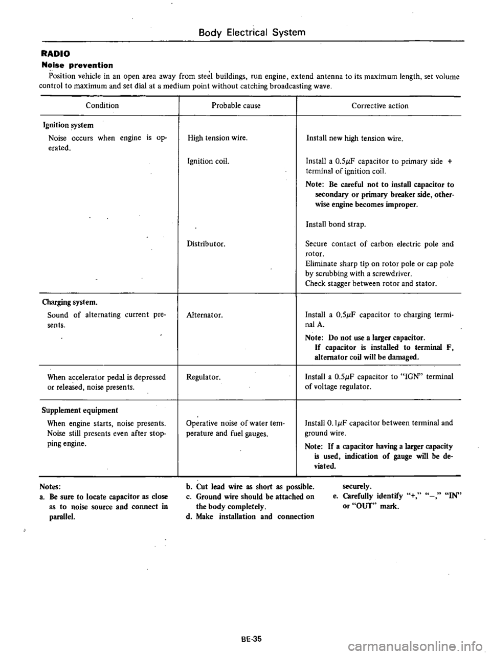
RADIO
Noise
prevention
Position
vehicle
in
an
open
area
away
from
steel
buildings
run
engine
extend
antenna
to
its
maximum
length
set
volume
control
to
maximum
and
set
dial
at
a
medium
point
without
catching
broadcasting
wave
Condition
Ignition
system
Noise
occurs
when
engine
is
op
erated
Charging
system
Sound
of
alternating
current
pre
sents
When
accelerator
pedal
is
depressed
or
released
noise
presents
Supplement
equipment
When
engine
starts
noise
presents
Noise
still
presents
even
after
stop
ping
engine
Notes
a
Be
sure
to
locate
capacitor
as
close
as
to
noise
source
and
connect
in
parallel
Probable
cause
Corrective
action
High
tension
wire
Install
new
high
tension
wire
Ignition
coil
Install
a
0
51lF
capacitor
to
primary
side
terminal
of
ignition
coil
Note
Be
careful
not
to
install
capacitor
to
secondary
or
primary
breaker
side
other
wise
engine
becomes
improper
Install
bond
strap
Distributor
Secure
contact
of
carbon
electric
pole
and
rotor
Eliminate
sharp
tip
on
rotor
pole
or
cap
pole
by
scrubbing
with
a
screwdriver
Check
stagger
between
rotor
and
stator
Alternator
Install
a
0
51lF
capacitor
to
charging
termi
nalA
Note
Do
not
use
a
larger
capacitor
If
capacitor
is
installed
to
terminal
F
alternator
coil
will
be
damaged
Regulator
Install
a
0
51lF
capacitor
to
IGN
terminal
of
voltage
regulator
Operative
noise
of
water
tem
perature
and
fuel
gauges
Install
O
IIlF
capacitor
between
terminal
and
ground
wire
Note
If
a
capacitor
having
a
larger
capacity
is
used
indication
of
gauge
will
be
de
viated
b
Cut
lead
wire
as
short
as
possible
c
Ground
wire
should
be
attached
on
the
body
completely
d
Make
installation
and
connection
securely
e
Carefully
identify
or
OUT
mark
IN
BE
35
Page 485 of 537

m
J
c
@
@
r
1
I
I
I
II
U
j
J
r
U
I
IT
L
U
L
L
@
Qj
flll
I
1
I
I
1
lL
to
t
l
Q
1
To
room
Jamp
cable
2
To
light
switch
3
To
fuse
4
To
tachometer
or
clock
5
To
hazard
flasher
unit
6
To
stop
lamp
switch
7
To
ignition
switch
8
To
hazard
switch
9
To
tU
and
dimmer
switch
10
To
check
connector
11
To
AMP
M
T
only
11
To
combination
instrument
Non
California
mode15
except
for
Canada
13
To
combination
meter
14
To
flasher
unit
IS
To
kickdown
switch
AfT
only
16
To
hand
brake
switch
17
To
heater
motor
18
To
illumination
control
rheostat
19
To
wiper
switch
light
switch
illumination
lamp
20
To
wiper
switch
21
To
cigar
lighter
22
To
heater
control
illumination
lamp
23
To
radio
24
To
heater
control
25
To
belt
and
E
G
R
warning
lamp
Non
California
models
or
floor
te
peratuJe
California
models
26
To
heater
control
illumination
lamp
27
To
buzzer
28
To
belt
warning
timer
U
S
A
Olodels
29
To
indicator
lamp
AfT
only
30
To
cooler
harness
31
To
wiptr
motor
32
To
door
switch
R
H
33
To
engine
compartment
harness
34
To
floor
harness
E
m
S
@
o
J
o
Q
m
CD
n
Ql
en
I
i
3