sensor DATSUN PICK-UP 1977 Service Manual
[x] Cancel search | Manufacturer: DATSUN, Model Year: 1977, Model line: PICK-UP, Model: DATSUN PICK-UP 1977Pages: 537, PDF Size: 35.48 MB
Page 27 of 537
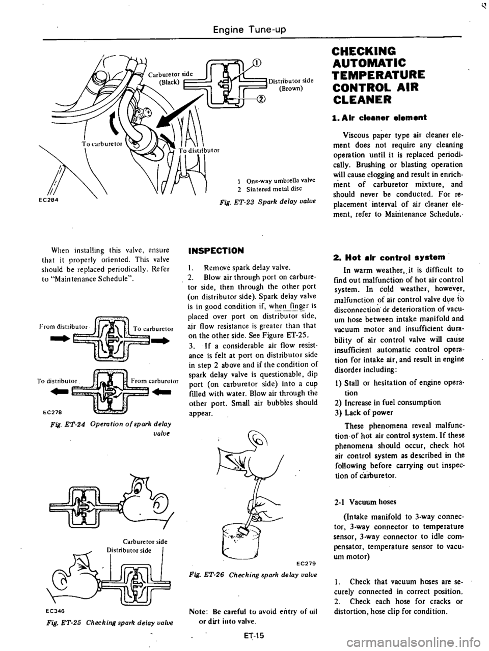
Engine
Tune
up
EC284
When
installing
this
valve
ensure
that
it
properly
oriented
This
valve
should
be
replaced
periodically
Refer
to
Maintenance
Schedule
I
To
distribut0
From
carburetor
Yl
r
EC278
l
Fig
ET
24
Operation
of
spark
delay
value
I
I
Carburetor
side
Distributor
side
rJmlL
lr
EC346
Fig
ET
25
Checking
spark
delay
value
Distributor
side
Brown
lOne
way
umbrella
valve
2
Sintered
metal
disc
Fig
ET
23
Spark
delay
valve
INSPECTION
I
Remove
spark
delay
valve
2
Blow
air
through
port
on
carbure
tor
side
then
through
the
other
port
on
distributor
side
Spark
delay
valve
is
in
good
condition
if
when
finger
is
placed
over
port
on
distrib
side
ajr
flow
resistance
is
greater
than
that
on
the
other
side
See
Figure
ET
25
3
If
a
considerable
air
flow
resist
ance
is
felt
at
port
on
distributor
side
in
step
2
above
and
if
the
condition
of
spark
delay
valve
is
questionable
dip
port
on
carburetor
side
into
a
cup
fIlled
with
water
Blow
air
through
the
other
port
Small
air
bubbles
should
appear
EC279
Fig
ET
26
Checking
spark
delay
ualue
Note
Be
careful
to
avoid
entry
of
oil
or
dirt
into
valve
ET
15
CHECKING
AUTOMATIC
TEMPERATURE
CONTROL
AIR
CLEANER
1
Air
cleener
element
Viscous
paper
type
air
cleaner
ele
ment
does
not
require
any
cleaning
opera
tion
until
it
is
replaced
periodi
cally
Brushing
or
blasting
operation
will
cause
clogging
and
result
in
enrich
ment
of
carburetor
mixture
and
should
never
be
conducted
For
reo
placement
interval
of
air
cleaner
ele
ment
refer
to
Maintenance
Schedule
2
Hot
elr
control
system
In
warm
wealher
it
is
difficult
to
find
ou
t
malfunction
of
hot
air
control
system
In
cold
weather
however
malfunction
of
air
control
valve
d
e
to
disconnection
or
deterioration
of
vacu
um
hose
between
intake
manifold
and
vacuum
motor
and
insufficient
dura
bili
ty
of
air
con
trol
valve
will
cause
insufficient
automatic
control
opera
tion
for
intake
air
and
result
in
engine
disorder
including
I
Stall
or
hesitation
of
engine
opera
tion
2
Increase
in
fuel
consumption
3
Lack
of
power
These
phenomena
reveal
malfunc
tionof
hot
air
control
system
If
these
phenomena
should
occur
check
hot
air
control
system
as
described
in
the
following
before
carrying
ou
t
inspec
tion
of
carburetor
2
1
Vacuum
hoses
Intake
manifold
to
3
way
connec
tor
3
way
connector
to
temperature
sensor
3
way
connector
to
idle
com
pensator
temperature
sensor
to
vacu
um
motor
1
Check
that
vacuum
hoses
are
se
curely
connected
in
correct
position
2
Check
each
hose
for
cracks
or
distortion
hose
clip
for
condition
Page 28 of 537
Note
Vacuum
hose
position
R
R
side
of
Nissan
mark
on
the
top
of
sensor
for
intake
manifold
L
R
side
of
the
mark
is
for
vacuum
rootor
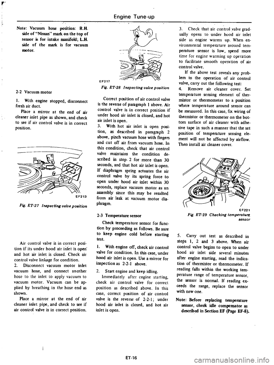
2
2
Vacuum
motor
I
With
engine
stopped
disconnect
fresh
air
duct
Place
a
mirror
at
the
end
of
air
cleaner
inlet
pipe
as
shown
and
check
to
see
if
air
control
valve
is
in
correct
position
EF213
Fig
ET
27
Impecting
lJalv
position
Air
control
valve
is
in
correct
posi
tion
if
its
under
hood
air
inlet
is
open
and
hot
air
inlet
is
closed
Check
air
control
valve
linkage
for
condition
2
Disconnect
vacuum
motor
inlet
vacuum
hose
and
connect
another
hose
to
the
inlet
to
apply
vacuum
to
vacuum
motor
Vacuum
can
be
ap
plied
by
breathing
in
the
hose
end
as
shown
Place
a
mirror
at
the
end
of
air
cleaner
inlet
pipe
and
check
to
see
if
air
control
valve
is
in
correct
position
Engine
Tune
up
EF217
Fig
ET
28
lmpecting
value
position
Correct
pC6ition
of
air
control
valve
is
the
reverse
of
paragraph
I
above
Air
control
valve
is
in
correct
position
if
under
hood
air
inlet
is
closed
and
hot
air
inlet
is
open
3
With
hot
air
inlet
is
open
posi
tion
as
descnbed
in
paragraph
2
above
pinch
vacuum
hose
with
fingers
and
cut
of
air
from
vacuum
hose
In
this
condition
check
that
air
control
valve
maintains
the
condition
de
scribed
in
step
2
for
more
than
30
seconds
and
that
hot
air
inlet
is
open
If
diaphragm
spring
actuates
the
air
control
valve
by
its
spring
force
to
open
under
hood
air
inlet
within
30
seconds
replace
vacuum
motor
as
an
assembly
since
this
may
be
resulted
from
air
leak
at
vacuum
motor
dia
phragm
2
3
Temperature
sensor
Check
temperature
sensor
for
func
tion
by
proceeding
as
follows
Be
sure
to
keep
engine
cold
before
starting
test
1
With
engine
off
check
air
control
valve
for
condition
In
this
case
under
hood
air
inlet
is
open
Use
a
mirror
for
inspection
as
2
2
1
above
2
Start
engine
and
keep
idling
Immediately
after
engine
starting
check
air
control
valve
for
correct
position
as
described
above
In
this
case
correct
position
of
air
control
valve
is
the
reverse
of
2
2
1
under
hood
air
inlet
is
closed
and
hot
air
inlet
is
open
ET
16
3
Check
that
air
control
valve
grad
ually
opens
to
under
hood
air
inlet
side
as
engine
warms
up
When
en
vironmental
temperature
around
tern
perature
sensor
is
low
spend
more
time
for
engine
warming
up
operation
to
facilitate
smooth
opera
tion
of
air
con
trol
valve
If
the
above
test
reveals
any
prob
lem
in
the
operation
of
air
control
valve
carry
out
the
following
test
4
Remove
air
cleaner
cover
Set
temperature
sensing
element
of
ther
mistor
or
thermometer
to
a
position
where
tempera
ture
around
sensor
can
be
measured
In
this
case
fix
wiring
of
thermistor
or
thermometer
on
the
bot
tom
surface
of
air
cleaner
with
adhe
sive
tape
in
such
a
manner
that
the
set
position
of
temperature
sensing
ele
ment
will
not
be
affected
by
airflow
Then
install
air
cleaner
cover
EF221
Fig
ET
29
Checking
temperotur
e
ensor
5
Carry
out
test
as
described
in
steps
I
2
and
3
above
When
air
control
valve
begins
to
open
to
under
hood
air
inlet
side
severa
minutes
after
engine
starting
read
the
indica
tion
of
thermistor
or
thermometer
If
reading
falls
within
the
working
tern
perature
range
of
temperature
sensor
the
sensor
is
normaL
If
reading
ex
ceeds
the
range
replace
the
sensor
with
new
one
Note
Before
replacing
temperature
sensor
check
idle
compensator
as
described
in
Section
EF
page
EF
8
Page 41 of 537
Condition
IMPROPER
ENGINE
IDLING
Fuel
system
out
of
order
Low
compression
Others
High
engine
idle
speed
Engine
Tune
up
Probable
cause
Clogged
or
damaged
carburetor
jets
Incorrect
idle
adjustment
Clogged
air
cleaner
filter
Damaged
manifold
gaskets
or
carburetor
insulator
Improper
float
level
adjustment
Loose
air
hoses
or
air
fuel
mixture
hoses
of
carburetor
Malfunctioning
carburetor
choke
Malfunctioning
anti
backfire
valve
Malfunctioning
automatic
temperature
con
trol
air
cleaner
Inoperative
idle
compensator
Carbon
canister
purge
line
hose
damaged
or
disconnected
Stick
E
F
E
valve
shaft
Incorrect
valve
clearance
Extremely
low
revolution
Faulty
malfunction
of
the
ignition
system
spark
plug
high
tension
cable
breaker
point
ignition
coil
etc
Incorrect
basic
ignition
timing
Malfunction
of
choke
valve
or
linkage
Malfunction
of
vacuum
motor
sensor
or
hoses
of
air
cleaner
Incorrect
idle
adjustment
Clogged
air
cleaner
fdter
Malfunction
of
idle
compensator
of
air
cleaner
Malfunction
of
E
G
R
control
valve
Loose
manifold
and
cylinder
head
bolts
Dragged
accelerator
linkage
Incorrect
idle
adjustment
Malfunction
of
B
CDD
system
Malfunction
of
speed
switch
and
harness
ET
29
Corrective
action
Clean
or
replace
Adjust
Replace
element
Replace
gasket
or
insulator
Adjust
Check
for
loose
connections
Check
and
adjust
Check
for
loose
connection
of
vacuum
hose
Check
A
r
C
air
cleaner
Check
for
connection
of
idle
compensator
hose
or
replace
idle
compen
tor
Connect
or
replace
Repair
Previously
mentioned
Adjust
Adjust
Replace
Adjust
Adjust
Check
for
loose
hoses
Replace
system
com
ponents
if
necessary
Adjust
idle
speed
Replace
air
cleaner
fdter
Replace
Clean
or
replace
Retighten
bolts
Check
and
correct
accelerator
linkage
Adjust
idle
speed
Check
for
loose
vacuum
hose
and
harness
connections
Adjust
or
replace
if
necessary
Check
for
loose
connections
Repair
or
replace
if
necessary
Page 98 of 537
Engine
Fuel
AUTOMATIC
TEMPERATURE
CONTROL
A
T
C
AIR
CLEANER
DESCRIPTION
OPERATION
A
T
C
AIR
CLEANER
HOT
AIR
OPERATION
A
T
C
AIR
CLEANER
COLD
AIR
OPERATION
A
T
C
AIR
CLEANER
COLD
AND
HOT
AIR
OPERATION
TEMPERATURE
SENSOR
DESCRIPTION
The
air
cleaner
removes
dust
and
dirt
from
the
air
before
it
enters
the
carburetor
and
engine
It
also
muffles
noise
resulting
from
the
intake
of
air
into
the
engine
The
air
cleaner
especially
designed
for
improved
exhaust
emission
control
is
referred
to
as
Automatic
Tempera
ture
Control
Air
Cleaner
In
order
to
reduce
HC
emission
when
the
under
hood
temperature
is
below
300C
860F
the
automatic
temperature
control
system
maintains
the
tempera
ture
of
air
to
be
sucked
in
the
carbure
tor
at
30
to
540C
86
to
1290F
thereby
enabling
lean
setting
for
carburetor
calibration
n
addition
to
this
the
automatic
temperature
con
twl
system
is
effective
to
improve
warm
up
characteristics
of
the
engine
CONTENTS
EF
2
EF
3
VACUUM
MOTOR
AND
AIR
CONTROL
VALVE
REMOVAL
AND
INSTALLATION
TEMPERATURE
SENSOR
VACUUM
MOTOR
FRESH
AIR
DUCT
AIR
CLEANER
INSPECTION
1
AIR
CLEANER
ELEMENT
2
HOT
AIR
CONTROL
SYSTEM
EF
3
EF
4
EF
4
EF
5
and
to
remove
carburetor
icing
The
A
T
C
air
cleaner
system
con
sists
of
the
following
devices
1
Air
cleaner
element
The
air
cleaner
element
employed
is
a
viscous
paper
type
It
requires
only
periodical
replacment
and
should
not
be
cleaned
2
Automatic
temperature
control
air
cleaner
In
the
A
T
C
air
cleaner
the
air
control
valve
is
actuated
by
intake
manifold
vacuum
to
control
the
intake
air
flow
circuit
The
temperature
sen
sor
detects
the
temperature
inside
the
air
cleaner
and
opens
or
closes
the
vacuum
passage
3
Hot
air
duct
The
hot
air
duct
is
mounted
on
the
exhaust
manifold
The
air
warmed
up
EF
2
EF
5
EF
5
EF
5
EF
5
EF
5
EF
6
EF
6
EF
6
EF
6
between
the
exhaust
manifold
and
hot
air
duct
is
led
to
the
air
cleaner
through
the
hose
4
Blow
by
gas
filter
The
blow
by
gas
nIter
removes
dirt
and
oil
from
the
blow
by
gas
sucked
in
the
air
cleaner
from
the
engine
rocker
cover
5
Fresh
air
duct
Except
for
Canada
The
fresh
air
duct
leads
the
outside
fresh
air
directly
to
the
air
cleaner
6
Idle
compensator
See
paragraph
Idle
Compensator
Page
EF
7
7
Altitude
compensator
California
models
See
paragraph
Altitude
Compensa
tor
Page
EF
20
Page 99 of 537

Engine
Fuel
@
1
Fresh
air
duct
Except
for
Canada
2
Air
inlet
pipe
3
Vacuum
motor
assembly
4
Air
control
valve
5
Hot
air
pipe
6
Idle
compensator
7
Blow
by
gas
fiI
teT
8
Temperature
sensor
assembly
9
Altitude
compensator
California
models
EF713
Fig
EF
1
Automatic
temperature
control
air
cleaner
OPERATION
The
automatic
temperature
control
system
of
the
air
cleaner
is
controlled
by
the
inlet
air
temperature
and
the
load
condition
of
the
engine
The
inlet
air
temperature
is
detected
by
the
sensor
and
the
vacuum
motor
is
actu
ated
by
the
engine
intake
vacuum
Under
hood
air
Sensor
vacuum
at
Air
control
valve
Sensor
operation
temperature
vacuum
motor
side
operation
Below
60
mmHg
Open
cold
air
Below
300C
2
36
inHg
860
F
Close
Above
210
mmHg
Close
hot
air
8
27
inHg
30
to
540C
Half
open
Open
86
to
1290
F
cold
air
hot
air
Above
55
oC
Open
cold
air
Open
1310F
A
T
C
AIR
CLEANER
HOT
AIR
OPERATION
When
the
under
hood
air
tempera
ture
is
low
the
sensor
air
bleed
valve
remains
in
the
closed
position
and
establishes
vacuum
passage
between
the
intake
manifold
and
vacuum
motor
With
this
condition
the
vacu
urn
at
the
intake
manifold
side
actu
ates
the
air
control
valve
attached
to
the
vacuum
motor
diaphragm
to
intro
duce
hot
air
into
the
air
cleaner
through
the
hot
air
duct
on
the
ex
haust
manifold
EF
3
Page 100 of 537
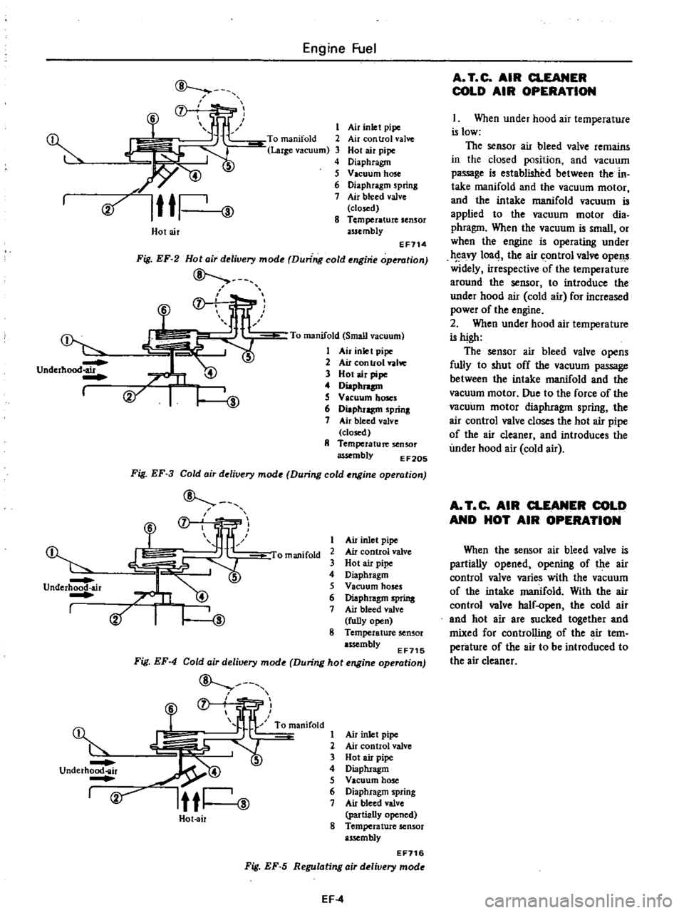
Underhood
air
I
@
Dr
Underhood
air
I
Engine
Fuel
f
f
l
l
ID
s
6
Cif
Ittl
ID
Air
inlet
pipe
Air
con
trol
valve
Hot
air
pipe
Diaphragm
Vacuum
hose
Diaphragm
spring
Air
bleed
valve
closed
Temperature
sensor
assembly
Holair
EF114
Fig
EF
2
Hota
r
delivery
mode
During
cold
engine
operation
7
To
manifold
Small
vacuum
1
Air
inlet
pipe
2
Air
con
trol
valw
3
Hot
air
pipe
4
Diaphnp
S
V
leuum
hoses
6
Diaphragm
prinl
7
Air
bleed
valve
closed
II
Temperature
senSOr
assembly
EF20S
Fig
EF
3
Cold
air
delivery
mode
During
cold
engine
operation
f
1
J
liP
omanifold
2
@
Air
inlet
pipe
Air
control
valve
Hot
air
pipe
Diaphragm
Vacuum
hoses
Diaphragm
spring
Air
bleed
valve
fully
open
8
Temperature
sensor
assembly
EF715
Fig
EF
4
Cold
air
delivery
mode
During
hot
engine
operation
ID
@
f
fjr
R
lfl
ow
2
underh
r
5
rv
Itti
ID
Hot
air
Air
inlet
pipe
Air
control
valve
Hot
air
pipe
Diaphragm
Vacuum
hose
Diaphragm
spring
Air
bleed
valve
partially
opened
8
Temperature
sensor
assembly
EF716
Fig
EF
5
Regulating
air
delivery
mode
EF
4
A
T
C
AIR
CLEANER
COLD
AIR
OPERATION
I
When
under
hood
air
temperature
is
low
The
sensor
air
bleed
valve
remains
in
the
closed
position
and
vacuum
passage
is
established
between
the
in
take
manifold
and
the
vacuum
motor
and
the
intake
manifold
vacuum
is
applied
to
the
vacuum
motor
dia
phragm
When
the
vacuum
is
small
or
when
the
engine
is
operating
under
eavy
1004
the
air
control
valve
opens
widely
irrespective
of
the
temperature
around
the
sensor
to
introduce
the
under
hood
air
cold
air
for
increased
power
of
the
engine
2
When
under
hood
air
temperature
is
high
The
sensor
air
bleed
valve
opens
fully
to
shut
off
the
vacuum
passage
between
the
intake
manifold
and
the
vacuum
motor
Due
to
the
force
of
the
vacuum
motor
diaphragm
spring
the
air
control
valve
closes
the
hot
air
pipe
of
the
air
cleaner
and
introduces
the
under
hood
air
cold
air
A
T
C
AIR
CLEANER
COLD
AND
HOT
AIR
OPERATION
When
the
sensor
air
bleed
valve
is
partially
opened
opening
of
the
air
control
valve
varies
with
the
vacuum
of
the
intake
manifold
With
the
air
control
valve
half
open
the
cold
air
and
hot
air
are
sucked
together
and
mixed
for
controlling
of
the
air
tem
perature
of
the
air
to
be
introduced
to
the
air
cleaner
Page 101 of 537

TEMPERATURE
SENSOR
The
temperature
sensor
is
attached
to
the
inside
of
the
air
cleaner
The
bimetal
built
in
the
sensor
detects
the
under
hood
air
temperature
and
opens
or
closes
the
vacuum
passage
in
the
sensor
The
construction
of
the
tempera
ture
sensor
is
shown
in
the
following
CD
V
00
@
I
I
@
j
I
I
1
Protector
cover
Screw
Adjusting
frame
Air
temperature
bi
metal
Rivet
Valve
seat
frame
Lower
frame
Air
bleed
valve
Gasket
Fig
EF
6
Temperature
senior
EF206
VACUUM
MOTOR
AND
AIR
CONTROL
VALVE
The
vacuum
pressure
which
varies
with
opening
of
the
carburetor
throt
tle
acts
upon
the
vacuum
motor
dia
phragm
The
valve
shaft
attached
to
the
diaphragm
is
then
moved
up
or
down
in
response
to
the
vacuum
on
the
diaphragm
This
movement
of
the
valve
shaft
actuates
the
air
control
valve
to
control
the
temperature
of
the
air
to
be
introduced
into
the
air
cleaner
pr
to
I
1
Valve
spring
00
2
Diaphragm
@
3
Retainer
E
F
207
4
Valve
shaft
Fig
EF
7
Vacuum
motor
REMOVAL
AND
INSTALLATION
TEMPERATURE
SENSOR
Removal
Using
pliers
flatten
clip
con
Engine
Fuel
neeting
vacuum
hose
to
sensor
vacuum
tube
I
Pipe
2
Calch
3
Fixed
with
adhesive
4
Hose
5
Tab
6
Clip
7
Gasket
EC019
Fig
EF
B
Removal
of
semor
2
Disconnect
hose
from
sensor
3
Take
off
clip
from
sensor
vacuum
tube
and
dismount
sensor
body
from
air
cleaner
Note
The
gasket
between
sensor
and
air
cleaner
is
bonded
to
the
air
cleaner
side
and
should
not
be
removed
Inatallatlon
Mount
sensor
on
the
specified
position
For
mounting
position
of
sensor
see
the
following
EF717
Fig
EF
9
lalling
se
or
2
Insert
clip
into
vacuum
tube
of
sensor
After
installing
each
vacuum
hose
secure
hose
with
the
clip
Note
Be
sure
to
install
vacuum
hose
correctly
Correct
position
is
R
H
side
to
Nissan
mark
at
the
top
face
of
sensor
for
intake
manifold
L
H
side
for
vacuum
motor
VACUUM
MOTOR
1
Remove
screws
securing
vacuum
motor
to
air
cleaner
2
Disconnect
valve
shaft
attached
to
vacuum
motor
diapluagm
from
air
control
valve
and
remove
cacuum
motor
assembly
from
air
cleaner
3
To
install
reverse
the
removal
procedure
FRESH
AIR
DUCT
I
Disconnect
fresh
air
duct
at
air
cleaner
2
Fresh
air
duct
is
provided
with
projections
on
its
air
inlet
side
end
Hold
fresh
air
duct
with
a
hand
and
carefully
pull
out
from
radiator
core
support
while
turning
it
in
either
direction
3
To
install
reverse
the
removal
procedure
Be
sure
to
insert
projec
lions
of
fresh
air
duct
securely
into
mounting
hole
in
radiator
core
sup
port
EF518
EF
5
Fresh
air
duct
Air
cleaner
Duct
mounting
hole
Radiator
Radiator
core
support
Fig
EF
I0
Removal
of
fresh
air
duct
Page 102 of 537
r
AIR
CLEANER
1
Loosen
bolts
securing
air
cleaner
to
air
cleaner
bracket
2
Loosen
air
cleaner
lock
bolt
and
remove
air
cleaner
from
carburetor
Disconnect
the
following
hoses
when
dismounting
air
cleaner
Under
hood
air
inlet
hose
Hot
air
inlet
hose
Vacuum
hose
Sensor
to
intake
manifold
Vacuum
hose
Sensor
to
vacuum
motor
Vacuum
hose
Idle
compensator
to
intake
manifold
Hose
Air
pump
to
air
cleaner
Hose
AB
valve
to
air
cleaner
Hose
Carburetor
to
air
cleaner
Blow
by
hose
Air
cleaner
to
rocker
cover
Hose
Air
control
vaive
to
air
cleaner
California
models
only
3
To
install
reverse
the
removal
procedure
INSPECTION
1
AIR
CLEANER
ELEMENT
Viscous
paper
type
air
cleaner
ele
ment
does
not
require
any
cleaning
operation
until
it
is
replaced
periodi
cally
Brushing
or
blasting
operation
will
cause
clogging
and
result
in
enrich
ment
of
carburetor
mixture
and
should
never
be
conducted
For
reo
placement
interval
of
air
cleaner
ele
ment
refer
to
Maintenance
Sched
ule
2
HOT
AIR
CONTROL
SYSTEM
In
warm
weather
it
is
difficult
to
find
out
malfunction
of
hot
air
control
system
In
cold
wea
thee
however
malfunction
of
air
control
valve
due
to
disconnection
or
deterioration
of
vacu
um
hose
between
intake
manifold
and
vacuum
motor
and
insufficient
dura
bility
of
air
control
valve
will
cause
insufficient
automatic
control
opera
tion
for
intake
air
and
result
in
engine
disorder
including
I
Stall
or
hesitation
of
engine
oper
ation
2
Increase
in
fuel
consumption
3
uck
of
power
Engine
Fuel
These
phenomena
reveal
malfunc
tion
of
hot
air
control
system
If
these
phenomena
should
occur
check
hot
air
control
system
as
described
in
the
following
before
carrying
out
inspec
tion
of
carburetor
2
1
Vacuum
hose
Intake
manifold
to
3
way
connec
tor
3
way
connector
to
temperature
sensor
3
way
connector
to
idle
com
pensator
temperature
sensor
to
vacu
um
motor
I
Check
that
vacuum
hoses
are
se
curely
connected
in
correct
postion
2
Check
each
hose
for
cracks
or
distortion
hose
clip
for
condition
Note
Vacuum
hose
position
R
H
side
of
Nissan
mark
on
the
top
of
sensor
is
for
intake
manifold
L
U
side
of
the
mark
is
for
vacuum
motor
2
2
Vacuum
motor
I
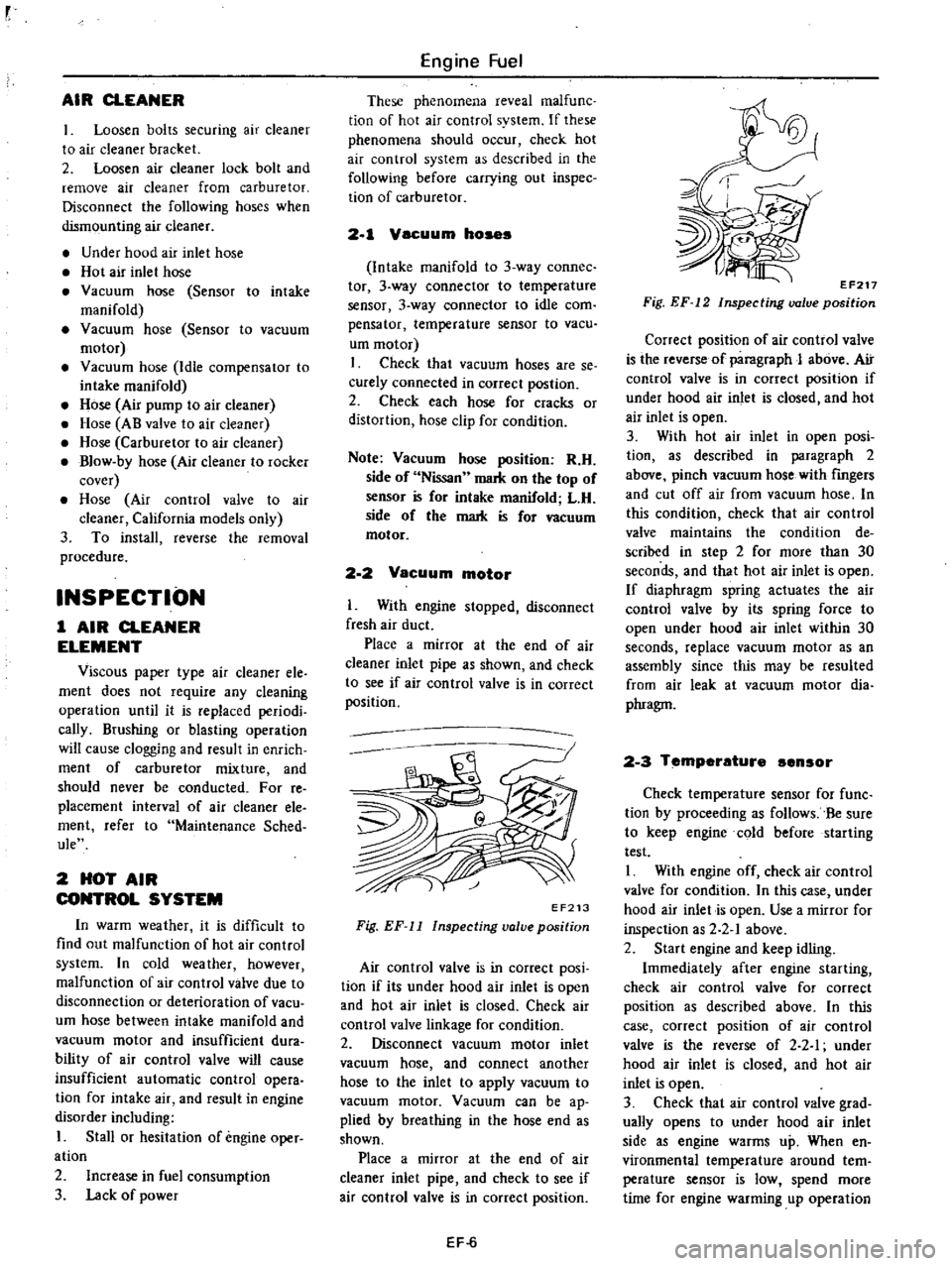
With
engine
stopped
disconnect
fresh
air
duct
Place
a
mirror
at
the
end
of
air
cleaner
inlet
pipe
as
shown
and
check
to
see
if
air
con
trol
valve
is
in
correct
position
EF213
Fig
EF
11
Inspecting
valve
position
Air
control
valve
is
in
correct
posi
tion
if
its
under
hood
air
inlet
is
open
and
hot
air
inlet
is
closed
Check
air
control
valve
linkage
for
condition
2
Disconnect
vacuum
motor
inlet
vacuum
hose
and
connect
another
hose
to
the
inlet
to
apply
vacuum
to
vacuum
motor
Vacuum
can
be
ap
plied
by
breathing
in
the
hose
end
as
shown
Place
a
mirror
at
the
end
of
air
cleaner
inlet
pipe
and
check
to
see
if
air
control
valve
is
in
correct
position
EF
6
EF217
Fig
EF
12
Inspecting
valve
position
Correct
position
of
air
control
valve
is
the
reverse
of
paragraph
J
above
Air
control
valve
is
in
correct
position
if
under
hood
air
inlet
is
closed
and
hot
air
inlet
is
open
3
With
hot
air
inlet
in
open
posi
tion
as
described
in
paragraph
2
above
pinch
vacuum
hose
with
fingers
and
cut
off
air
from
vacuum
hose
In
this
condition
check
that
air
control
valve
maintains
the
condition
de
scribed
in
step
2
for
more
than
30
seconds
and
that
hot
air
inlet
is
open
If
diaphragm
spring
actuates
the
air
control
valve
by
its
spring
force
to
open
under
hood
air
inlet
within
30
seconds
replace
vacuum
motor
as
an
assembly
since
this
may
be
resulted
from
air
leak
at
vacuum
motor
dia
phragm
2
3
Temperature
ensor
Check
temperature
sensor
for
func
tion
by
proceeding
as
follows
Be
sure
to
keep
engine
cold
before
starting
test
I
With
engine
off
check
air
control
valve
for
condition
In
this
case
under
hood
air
inlet
is
open
Use
a
mirror
for
inspection
as
2
2
1
above
2
Start
engine
and
keep
idling
Immediately
after
engine
starting
check
air
control
valve
for
correct
position
as
described
above
In
this
case
correct
position
of
air
control
valve
is
the
reverse
of
2
2
I
under
hood
air
inlet
is
closed
and
hot
air
inlet
is
open
3
Check
that
air
control
valve
grad
ually
opens
to
under
hood
air
inlet
side
as
engine
warms
up
When
en
vironmental
temperature
around
tern
perature
sensor
is
low
spend
more
time
for
engine
warming
up
operation
Page 103 of 537

to
facilitate
smooth
operation
of
air
control
valve
If
the
above
test
reveals
any
prob
lem
in
the
operation
of
air
control
valve
carry
out
the
following
test
4
Remove
air
cleaner
cover
Set
temperature
sensing
element
of
ther
mistor
or
thermometer
to
a
position
where
temperature
around
sensor
can
be
measured
In
this
case
fIx
wiring
of
thermistor
or
thermometer
on
the
bottom
surface
of
air
cleaner
with
adhesive
tape
in
such
a
manner
that
the
set
position
of
temperature
sensing
DESCRIPTION
OPERATION
DESCRIPTION
The
idle
compensator
is
basically
a
thermostatic
valve
which
functions
to
introduce
the
air
directly
from
the
air
cleaner
to
the
intake
manifold
to
compensate
for
abnormal
enrichment
of
mixture
in
high
idle
temperature
The
bi
metal
attached
to
the
idle
compensator
detects
the
temperature
of
intake
air
and
opens
or
closes
the
valve
Two
idle
compensators
having
different
temperature
characteristics
are
installed
one
opens
at
an
intake
air
temperature
of
60
to
700C
140
to
l580F
and
the
other
at
70
to
900C
158
to
1940F
OPERATION
The
construction
of
the
idle
com
pensator
is
shown
in
the
following
Engine
Fuel
element
will
not
be
affected
by
air
flow
Then
install
air
cleaner
cover
Fig
EF
13
Checking
temperature
sensor
IDLE
COMPENSATOR
CONTENTS
5
Carry
out
test
as
described
in
steps
I
2
and
3
above
When
air
control
valve
begins
to
open
to
under
hood
air
inlet
side
several
minutes
after
engine
starting
read
the
indica
tion
of
thermistor
or
thermometer
If
reading
falls
within
the
working
tern
perature
range
of
temperature
sensor
the
sensor
is
normal
If
reading
ex
ceeds
the
range
replace
the
sensor
with
new
one
Note
Before
replacing
temperature
sensor
check
idle
compensator
as
described
in
Idle
compensator
EF
7
EF
7
REMOVAL
AND
INSTALLATION
INSPECTION
EF
B
EF
8
q
EF222
1
Orifice
2
Bi
metal
3
Rubber
valve
Fig
EF
14
Structure
of
idle
compensator
Bi
metal
Intake
air
temperature
No
1
Below
600C
1400F
60
to
70
C
140
to
l580F
Above
700C
158
OF
Below
700C
1580F
70
to
900C
158
to
1940F
Above
900C
1940F
No
2
EF
7
The
idle
compensator
operates
in
response
to
the
under
hood
air
temper
ature
as
shown
below
Idle
compensator
operation
Fully
closed
Close
to
open
Fully
open
Fully
closed
Close
to
open
Fully
open
Page 467 of 537
Body
Electrical
System
Horn
switch
The
horn
switch
is
integral
with
the
turn
signal
and
dimmer
switch
as
sembly
Remove
switch
assembly
as
outlined
in
Turn
Signal
and
Dimmer
Switch
IGNITION
SWITCH
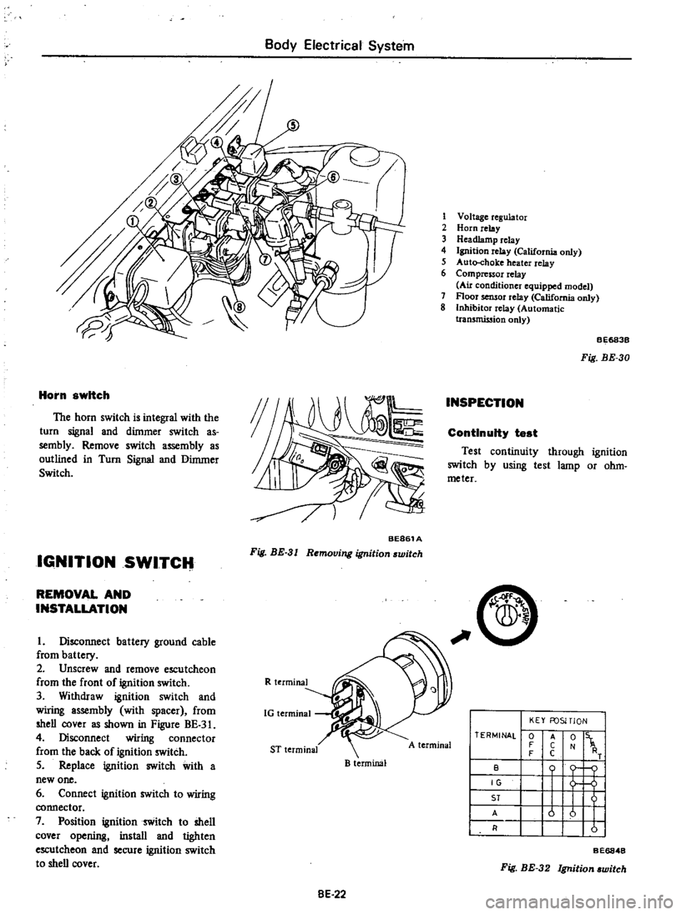
BE861A
Fig
BE
3
I
Removing
ignition
switch
REMOVAL
AND
INSTALLATION
I
Disconnect
battery
ground
cable
from
battery
2
Unscrew
and
remove
escutcheon
from
the
front
of
ignition
switch
3
Withdraw
ignition
switch
and
wiring
assembly
with
spacer
from
shell
cover
as
shown
in
Figure
BE
3
4
Disconnect
wiring
connector
from
the
back
of
ignition
switch
5
Replace
ignition
switch
with
a
new
one
6
Connect
ignition
switch
to
wiring
connector
7
Position
ignition
switch
to
shell
cover
opening
install
and
tighten
escutcheon
and
secure
ignition
switch
to
shell
cover
R
terminal
1G
terminal
ST
terminal
B
terminal
8E
22
1
Voltage
regulator
2
Horn
relay
3
Headlamp
relay
4
Ignition
relay
California
only
5
Auto
choke
heater
relay
6
Compressor
relay
Au
conditioner
equipped
model
7
Floor
sensor
relay
California
only
8
Inhibitor
relay
Automatic
tran5mission
only
INSPECTION
BE683B
Fig
BE
30
ContInuity
test
Test
continuity
through
ignition
switch
by
using
test
lamp
or
ohm
meter
C
A
terminal
TERMINAL
0
F
F
B
IG
ST
A
R
KEY
FOSITlON
t
1
o
j
u
u
I
I
A
C
C
Fig
BE
32
Ignition
witch
BE6848