engine oil capacity DATSUN PICK-UP 1977 Service Manual
[x] Cancel search | Manufacturer: DATSUN, Model Year: 1977, Model line: PICK-UP, Model: DATSUN PICK-UP 1977Pages: 537, PDF Size: 35.48 MB
Page 20 of 537
r
ManifolJ
nuts
I
2
to
1
6
kg
m
8
7
to
I
6
ft
lb
Carburelor
nuls
0
5
to
1
0
kg
m
3
6
to
7
2
fl
tb
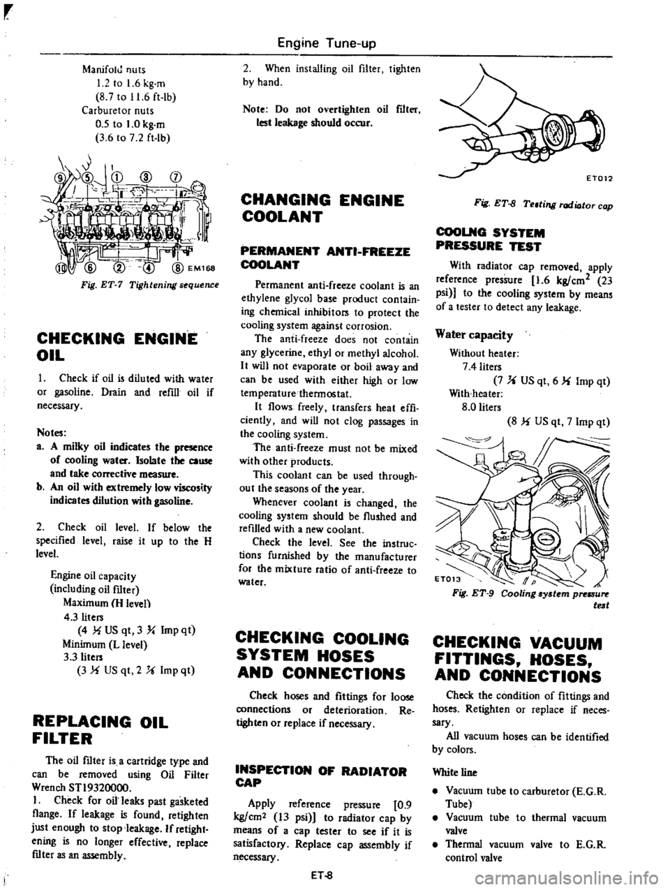
Fig
ET
7
Tightening
s
quence
CHECKING
ENGINE
OIL
Check
if
oil
is
diluled
with
water
or
gasoline
Drain
and
refill
oil
if
necessary
Notes
a
A
milky
oil
indicates
the
presence
of
cooling
water
Isolate
the
cause
and
take
corrective
measure
b
An
oil
with
extremely
low
viscosity
indicates
dilution
with
gasoline
2
Check
oil
level
If
below
the
specified
level
raise
it
up
10
the
H
level
Engine
oil
capacity
including
oil
filter
Maximum
H
leven
4
3
liters
4
MUS
qt
3
Y
Imp
qt
Minimum
L
level
3
3
liters
3
f
US
qt
2
U
Imp
ql
REPLACING
OIL
FILTER
The
oil
mter
is
a
cartridge
type
and
can
be
removed
using
Oil
Filter
Wrench
STI9320000
I
Check
for
oil
leaks
past
gasketed
flange
If
leakage
is
found
retighten
just
enough
to
stop
leakage
If
retight
ening
is
no
longer
effective
replace
mter
as
an
assembly
Engine
Tune
up
2
When
installing
oil
filter
tighlen
by
hand
Note
Do
not
overtighten
oil
flIt
lest
leakage
should
occur
CHANGING
ENGINE
COOLANT
PERMANENT
ANTI
FREEZE
COOLANT
Permanent
anti
freeze
coolant
is
an
ethylene
glycol
base
producl
conlain
ing
chemical
inhibilors
10
protect
the
cooling
system
against
corrosion
The
anti
freeze
does
not
contain
any
glycerine
ethyl
or
methyl
alcohol
It
will
not
evaporate
or
boil
away
and
can
be
used
with
either
high
or
low
temperaturethennoslat
It
flows
freely
transfers
heat
effi
ciently
and
will
not
clog
passages
in
the
cooling
system
The
anti
freeze
must
not
be
mixed
with
other
products
This
coolant
can
be
used
through
out
the
seasons
of
the
year
Whenever
coolant
is
changed
the
cooling
syslem
should
be
flushed
and
refilled
with
a
new
coolant
Check
the
level
See
the
instruc
lions
furnished
by
the
manufacturer
for
the
mixture
ratio
of
anti
freeze
10
water
CHECKING
COOLING
SYSTEM
HOSES
AND
CONNECTIONS
Check
hoses
and
fittings
for
loose
connections
or
deterioration
Re
tighten
or
replace
if
necessary
INSPECTION
OF
RADIATOR
CAP
Apply
reference
pressure
0
9
kg
cm2
13
psi
1
to
radiator
cap
by
means
of
a
cap
tester
to
see
if
it
is
satisfactory
Replace
cap
assembly
if
necessary
ET
8
Fig
ET
fJ
Teltill
l
rod
ioto
cop
COOLNG
SYSTEM
PRESSURE
TEST
With
radiator
cap
removed
apply
reference
pressure
1
6
kg
cm2
23
psi
to
the
cooling
system
by
means
of
a
lesler
to
detect
any
leakage
Water
capacity
Without
heater
7
4
liters
7
U
US
qt
6
f
Imp
qt
With
heater
8
0
liters
8
f
US
qt
7
Imp
qt
CHECKING
VACUUM
FITTINGS
HOSES
AND
CONNECTIONS
Check
the
condition
of
filtings
and
hoses
Retighten
or
replace
if
neces
sary
All
vacuum
hoses
can
be
identified
by
colors
White
line
Vacuwn
tube
to
carburetor
E
G
R
Tube
Vacuum
tube
to
thermal
vacuum
valve
Thennal
vacuum
valve
to
E
G
R
control
valve
Page 23 of 537
EE322
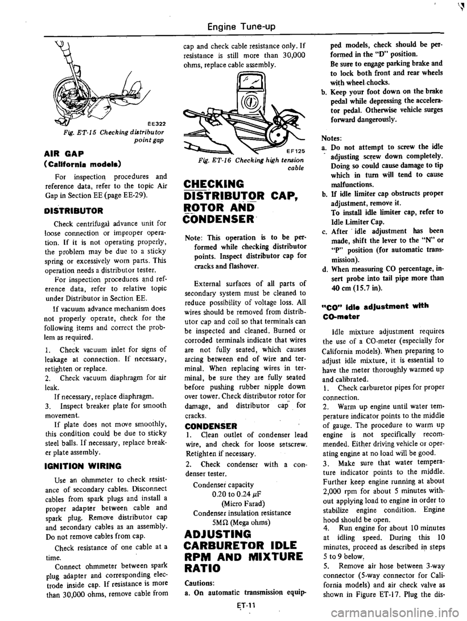
Fig
ET
15
Checking
diltribu
tor
point
gap
AIR
GAP
California
models
For
inspection
procedures
and
reference
data
refer
to
the
topic
Air
Gap
in
Section
EE
page
EE
29
DISTRIBUTOR
Check
centrifugal
advance
unit
for
loose
connection
or
improper
opera
tion
If
it
is
not
operating
properly
the
problem
may
be
due
to
a
sticky
spring
or
excessively
worn
parts
This
operation
needs
a
distributor
tester
For
inspection
procedures
and
ref
erence
data
refer
to
relative
topic
under
Distributor
in
Section
EE
If
vacuum
advance
mechanism
does
not
properly
operate
check
for
the
following
items
and
correct
the
prob
lem
as
required
1
Check
vacuum
inlet
for
signs
of
leakage
at
connection
If
necessary
retighten
or
replace
2
Check
vacuum
diaphragm
for
air
leak
If
necessary
replace
diaphragm
3
Inspect
breaker
plate
for
smooth
movement
If
plate
does
not
move
smoothly
this
condition
could
be
due
to
sticky
steel
balls
If
necessary
replace
break
er
plate
assembly
IGNITION
WIRING
Use
an
ohmmeter
to
check
resist
ance
of
secondary
cables
Disconnect
cables
from
spark
plugs
and
install
a
proper
adapter
between
cable
and
spark
plug
Remove
distributor
cap
and
secondary
cables
as
an
assembly
Do
not
remove
cables
from
cap
Check
resistance
of
one
cable
at
a
time
Connect
ohmmeter
between
spark
plug
adapter
and
corresponding
elec
trade
inside
cap
If
resistance
is
more
than
30
000
ohms
remove
cable
from
Engine
Tune
up
cap
and
check
cable
resistance
only
If
resistance
is
still
more
than
30
000
ohms
replace
cable
assembly
EF125
Checking
high
tension
cable
CHECKING
DISTRIBUTOR
CAP
ROTOR
AND
CONDENSER
Note
This
operation
is
to
be
per
formed
while
checking
distributor
points
Inspect
distributor
cap
for
cracks
and
flashover
External
surfaces
of
all
parts
of
secondary
system
must
be
cleaned
to
reduce
possibility
of
voltage
loss
All
wires
should
be
removed
from
distrib
utor
cap
and
coil
so
that
terminals
can
be
inspected
and
cleaned
Burned
or
corroded
terminals
indicate
that
wires
are
not
fully
seated
which
causes
arcing
between
end
of
wire
and
ter
minal
When
replacing
wires
in
ter
minai
be
sure
they
are
fully
seated
before
pushing
rubber
nipple
down
over
tower
Check
distributor
rotor
for
damage
and
distributor
cap
for
cracks
CONDENSER
I
Clean
outlet
of
condenser
lead
wire
and
check
for
loose
setscrew
Retighten
if
necessary
2
Check
condenser
with
a
con
denser
tester
Condenser
capacity
0
20
to
0
24
IF
Micro
Farad
Condenser
insulation
resistance
5Mn
Mega
ohms
ADJUSTING
CARBURETOR
IDLE
RPM
AND
MIXTURE
RATIO
Cautions
a
On
automatic
transmission
equip
T
11
ped
models
check
should
be
per
fonned
in
the
D
position
Be
sure
to
engage
parking
brake
and
to
lock
both
front
and
rear
wheels
with
wheel
chocks
b
Keep
your
foot
down
on
the
brake
pedal
while
depressing
the
accelera
tor
pedal
Otherwise
vehicle
surges
forward
dangerously
Notes
a
Do
not
attempt
to
screw
the
idle
adjusting
sc
ew
down
completely
Doing
so
could
cause
damage
to
tip
which
in
turn
will
tend
to
cause
malfunctions
b
If
idle
limiter
cap
obstructs
proper
adjustment
remove
it
To
install
idle
limiter
cap
refer
to
Idle
Limiter
Cap
c
After
idle
adjustment
has
been
made
shift
the
lever
to
the
N
or
P
position
for
automatic
trans
mission
d
When
measuring
CO
percentage
in
sert
probe
into
tail
pipe
more
than
40
em
15
7
in
CO
idle
adjustment
with
CD
meter
Idle
mixture
adjustment
requires
the
use
of
a
CO
meter
especially
for
California
models
When
preparing
to
adjust
idle
mixture
it
is
essential
to
have
the
meter
thoroughly
warmed
up
and
calibrated
I
Check
carburetor
pipes
for
proper
connection
2
Warm
up
engine
until
water
tem
perature
indicator
points
to
the
middle
of
gauge
The
procedure
to
warm
up
engine
is
not
specifically
recom
mended
Either
driving
vehicle
or
oper
ating
engine
at
no
load
will
be
good
3
Make
sure
that
water
tempera
ture
indicator
points
to
the
middle
Further
keep
engine
running
at
about
2
000
rpm
for
about
5
minutes
with
out
applying
load
to
engine
in
order
to
stabilize
engine
condition
Engine
hood
should
be
open
4
Run
engine
for
about
10
minutes
at
idling
speed
During
this
10
minutes
proceeq
as
described
i
steps
5
to
9
below
5
Remove
air
hose
between
3
way
connector
5
way
connector
for
Cali
fornia
models
and
air
check
valve
as
shown
in
Figure
ET
17
Plug
the
dis
Page 106 of 537

4
Run
the
engine
at
varying
speeds
5
The
pressure
gauge
indicates
static
fuel
pressure
in
the
line
The
gauge
reading
should
be
within
the
following
range
0
21
to
0
27
kg
em2
3
0
to
3
8
psi
Note
If
the
fuel
in
carburetor
float
chamber
has
run
out
and
engine
has
stopped
clip
and
pour
fuel
into
carburetor
Fasten
clip
secure
ly
and
repe
1
static
pressure
test
Pressure
below
the
lower
limit
indi
cates
extreme
wear
on
one
part
or
a
small
amount
of
wear
on
each
working
part
It
also
indicates
ruptured
dia
phragm
worn
warped
dirty
or
gum
ming
valves
and
seats
or
a
weak
diaphragm
return
spring
Pressure
above
the
upper
limit
indicates
an
excessively
strong
tension
of
dia
phragm
return
spring
or
a
diaphragm
that
is
too
tight
Both
of
these
condi
tions
require
the
removal
of
pump
assembly
for
replacement
or
repair
CAPACITY
TEST
The
capacity
test
is
made
only
when
static
pressure
is
within
the
specifications
To
make
this
test
pro
ceed
as
follows
1
Disconnect
pressure
gauge
from
T
connector
and
in
its
vacant
place
install
a
suitable
container
as
a
fuel
sump
2
Run
engine
at
1
000
rpm
3
The
pump
should
deliver
1
000
cc
2
11
US
pt
of
fuel
in
one
minute
or
less
If
little
or
no
fuel
flows
from
the
open
end
of
pipe
it
is
an
indication
that
fuel
line
is
clogged
or
pump
is
malfunctioning
REMOVAL
AND
DISASSEMBLY
Remove
fuel
pump
assembly
by
unscrewing
two
mounting
nuts
and
disassemble
in
the
following
order
1
Separate
upper
body
and
lower
body
by
unscrewing
body
set
screws
Engine
Fuel
2
Take
off
cap
and
cap
gasket
by
removing
cap
screws
3
Unscrew
elbow
and
connector
4
Take
off
valve
retainer
by
un
screwing
two
retainer
screws
and
re
move
two
valves
5
To
remove
diaphragm
press
down
its
center
against
spring
force
With
diaphragm
pressed
down
tilt
it
until
the
end
of
pull
rod
touches
the
inne
wall
of
body
Then
release
diaphragm
to
unhook
push
rod
Be
careful
during
this
operation
not
to
damage
diaphragm
or
oil
se
L
i
J
EFOO7
Fig
EF
20
Remouing
pull
rod
6
Drive
rocker
arm
pin
out
with
a
press
or
hammer
8
o
6
7
8
@
INSPECTION
I
Check
upper
body
and
lower
body
for
cracks
EF
10
I
fuel
pump
cap
2
Cap
gasket
3
Valve
packing
4
fuel
pump
val
e
assembly
S
Valve
retainer
6
Diaphragm
assembly
7
Diaphragm
spring
8
PuRro
9
Lower
body
seal
washer
10
Lower
body
seal
11
Inkl
connector
12
Outlet
connector
13
Rocker
arm
spring
14
Rocker
arm
I
S
Rocker
artyl
side
pin
16
Fuel
pump
packing
17
Spacer
fuel
pump
fo
cylinder
block
EF510
Fig
EF
21
Slruc
ure
of
fuel
pump
2
Check
valve
assembly
for
wear
on
valve
and
valve
spring
Blow
valve
assembly
with
brea
th
to
examine
its
function
Page 107 of 537
3
Check
diaphragm
for
small
holes
carcks
or
wear
4
Check
rocker
arm
for
wear
at
the
mating
portion
with
camshaft
5
Check
rocker
arm
pin
for
wear
A
worn
pin
may
cause
oil
leakage
6
Check
all
other
components
for
any
abnormalities
and
replace
if
neces
sary
DESCRIPTION
INSPECTION
REMOVAL
AND
INSTALLATION
DESCRIPTION
The
electric
fuel
pump
is
adopted
on
air
conditioner
equipped
models
Engine
Fuel
ASSEMBLY
Reverse
the
order
of
disassembly
Closely
observe
the
following
instruc
tions
L
Use
new
gaskets
2
Lubricate
rocker
ann
rocker
arm
link
and
rocker
arm
pin
before
installa
tion
3
To
test
the
function
proceed
as
follows
Position
fuel
pump
assembly
about
I
meter
3
3
ft
above
fuel
level
of
fuel
strainer
and
connect
a
pipe
from
strainer
to
fuel
pump
Operate
rocker
arm
by
hand
If
fuel
is
drawn
up
soon
after
rocker
arm
is
released
fuel
pump
is
functioning
properly
ELECTRIC
FUEL
PUMP
CONTENTS
EF
11
EF
11
EF
12
DISASSEMBL
Y
ASSEMBL
Y
TROUBLE
DIAGNOSES
AND
CORRECTIONS
EF
12
EF
12
The
silicon
transistor
type
fuel
pump
consists
of
a
transistor
diodes
a
sole
I
Tr
lOsistor
6
Ou
tIet
valve
2
Plunger
7
Return
spring
3
Diaphragm
8
Filter
4
Diode
9
Magnet
5
Magnet
coil
10
Inlet
valve
INSPECTION
I
Disconnect
fuel
hose
at
pump
outlet
2
Connect
a
suitable
hose
approxi
mately
6
mm
0
24
in
inner
dia
meter
to
pump
outlet
ev
J
J
Note
If
diameter
is
too
small
the
following
proper
delivery
capacity
cannot
be
obtained
even
if
pump
functions
properly
EF
11
EF
13
noid
a
pump
mechanism
and
filter
parts
I
T
nsistor
2
Re
ist
f
I
3
Dinde
4
Signal
coil
5
Main
coil
6
Resistor
3
7
Zener
dlOdl
8
Resistor
2
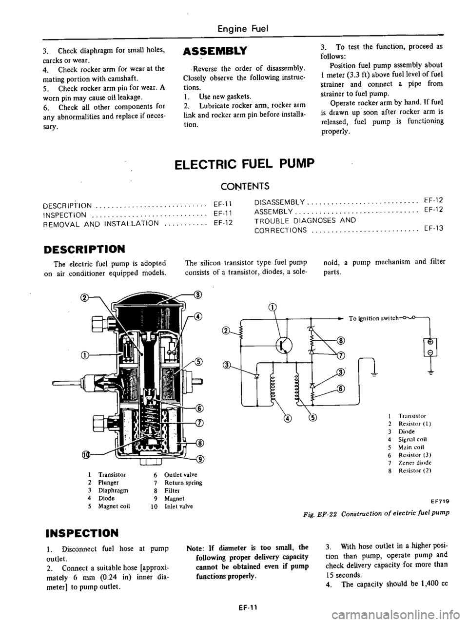
EF719
Fig
EF
22
Construction
of
electric
fuel
pump
3
With
hose
outlet
in
a
higher
posi
tion
than
pump
operate
pump
and
check
delivery
capacity
for
more
than
15
seconds
4
The
capacity
should
be
I
400
cc
Page 135 of 537

There
are
three
types
of
control
system
These
are
J
Closed
type
CIllnkcase
emission
control
system
Emission
Control
System
of
GENERAL
DESCRIPTION
2
Exhaust
emission
control
system
3
Evaporative
ell
lhsion
control
sys
tem
Pericxiic
inspection
and
required
seCV1Clng
of
these
systems
should
be
carried
out
to
reduce
harmful
emis
sions
to
a
minimum
CRANKCASE
EMISSION
CONTROL
SYSTEM
c
01
Lkf
If
1
TIL
II
tll
1
j
GUuuu
DESCRIPTION
This
system
returns
blow
by
gas
to
both
the
intake
manifold
and
carbure
tor
air
cleaner
The
positive
crankcase
ventilation
p
C
V
valve
is
provided
to
conduct
crankcase
blow
by
gas
to
the
intake
manifold
During
partial
throttle
operation
of
the
engine
the
intake
manifold
sucks
the
blow
by
gas
through
the
P
C
V
valve
Normally
the
capacity
of
the
valve
is
sufficient
to
handle
any
blow
by
and
a
small
amount
of
ventilating
air
4
c
Fresh
air
Blow
by
gas
The
ventilating
air
is
then
drawn
from
the
dust
side
of
the
cadlUretor
air
cleaner
tluough
the
tube
con
necting
carburetor
air
cleaner
to
rock
er
cover
into
the
crankcase
Under
full
tluottle
condition
the
manifold
vacuwn
is
insufficient
to
draw
the
blow
by
flow
tluough
the
valve
and
its
flow
goes
through
the
tube
connection
in
the
reverse
diree
tion
On
vehicles
with
an
excessively
high
blow
by
some
of
the
flow
will
go
through
the
tube
connection
to
carbu
retor
air
cleaner
under
all
conditions
1
Sealtypc
oil
level
gauge
2
Bame
plate
3
Flame
arrester
4
Filler
5
P
C
Y
valve
6
Steel
net
7
Bame
plate
EC716
Fig
EC
l
Crankcase
miaion
control
ay
tem
EC
2
INSPECTION
P
c
V
VALVE
AND
FILTER
Checking
P
C
V
valve
in
accord
ance
with
the
following
method
With
engine
running
at
idle
remove
the
ventilator
hose
from
P
C
V
valve
if
the
valve
is
working
a
hissing
noise
will
be
heard
as
air
passes
through
the
valve
and
a
strong
vacuwn
should
be
felt
immediately
when
a
fmger
is
placed
over
valve
inlet
Replace
P
C
V
valve
and
filter
in
accordance
with
the
maintenance
schedule
VENTILATION
HOSE
1
Check
hoses
and
hose
connec
tions
for
leaks
2
Disconnect
all
hoses
and
clean
with
compressed
air
If
any
hose
cannot
be
free
of
obstructions
replace
Ensure
that
flame
arrester
is
surely
inserted
in
hose
between
air
cleaner
and
rocker
cover
Page 198 of 537
CHECKING
AND
ADJUSTMENT
CAP
AND
ROTOR
HEAD
Cap
and
rotor
head
should
be
in
spected
periodically
as
specified
in
the
Maintenance
Schedule
Remove
cap
and
clean
all
dust
and
carbon
deposits
from
cap
and
rotor
If
cap
is
cracked
or
is
leaking
replace
with
a
De
one
CONTACT
POINT
Contact
point
should
be
replaced
in
accordance
with
the
Maintenance
Schedule
Standard
point
gap
is
0
45
to
0
55
mm
O
OIS
to
0
022
in
In
case
size
is
off
the
standard
adjustment
is
made
by
loosening
point
screws
Gap
gauge
is
required
for
adjustment
When
point
surface
is
rough
take
off
any
irregularities
with
fine
sand
paper
of
No
500
or
600
or
with
oil
stone
When
wear
on
contact
points
is
noticeable
replace
points
together
with
contact
arm
To
replace
proceed
as
follows
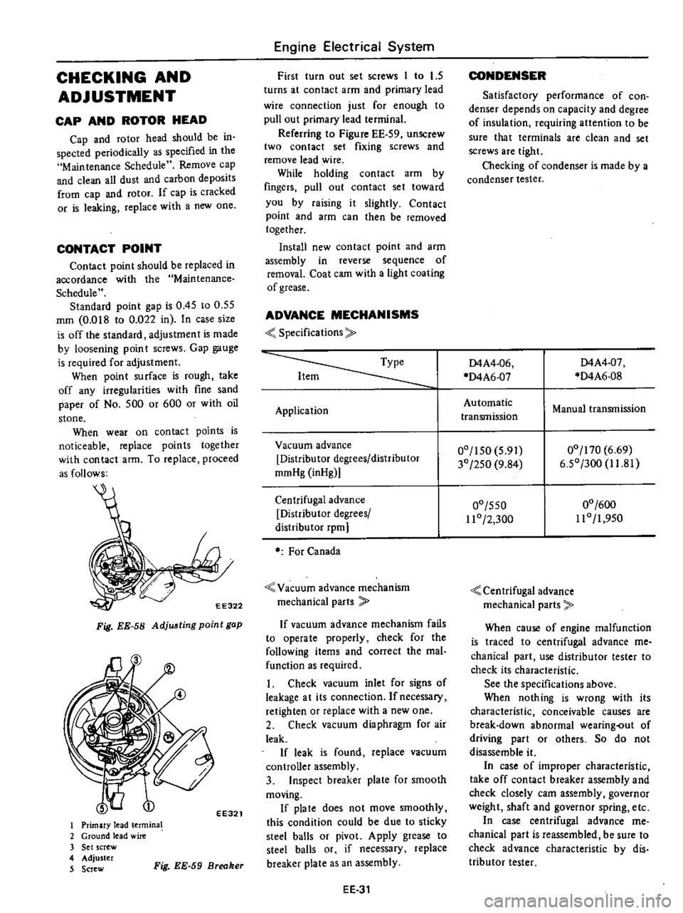
EE322
Fig
EE
58
Adju
ting
point
gap
EE321
I
Primary
lead
termina
2
Ground
lead
wire
3
Set
screw
4
Adjuster
5
Screw
Fig
EE
59
Breaker
Engine
Electrical
System
First
turn
out
set
screws
1
to
1
5
turns
at
contact
arm
and
primary
lead
wire
connection
just
for
enough
to
pull
out
primary
lead
terminal
Referring
to
Figure
EE
59
unSCrew
two
contact
set
fixing
screws
and
remove
lead
wire
While
holding
contact
arm
by
fingers
pull
out
contact
set
toward
you
by
raising
it
slightly
Contact
point
and
afm
can
then
be
removed
together
Install
new
contact
point
and
arm
assembly
in
reverse
sequence
of
removal
Coat
cam
with
a
light
coating
of
grease
ADVANCE
MECHANISMS
Specifications
Application
Vacuum
advance
Distributor
degrees
distributor
mmHg
inHg
Centrifugal
advance
Distributor
degrees
distribu
tor
rpm
For
Canada
Vacuum
advance
mechanism
mechanical
parts
If
vacuum
advance
mechanism
fails
to
operate
properly
check
for
the
following
items
and
correct
the
mal
function
as
required
1
Check
vacuum
inlet
for
signs
of
leakage
at
its
connection
Ifnecessacy
retighten
or
replace
with
a
new
one
2
Check
vacuum
diaphragm
for
air
leak
If
leak
is
found
replace
vacuum
controller
assembly
3
Inspect
breaker
plate
for
smooth
moving
If
pia
te
does
not
move
smoothly
this
condition
could
be
due
to
sticky
steel
balls
or
pivot
Apply
grease
to
steel
balls
or
if
necessary
replace
breaker
plate
as
an
assembly
EE
31
CONDENSER
Satisfactory
performance
of
con
denser
depends
on
capacity
and
degree
of
insulation
requiring
attention
to
be
sure
that
terminals
are
clean
and
set
screws
are
tight
Checking
of
condenser
is
made
by
a
condenser
tester
D4A4
06
D4A6
07
D4A4
07
D4A6
0S
Automatic
transmission
Manual
transmission
00
150
5
91
30
250
9
S4
00
170
6
69
6
50
300
1I
S1
00
550
11
0
2
300
00
600
110
1
950
Centrifugal
advance
mechanical
parts
When
cause
of
engine
malfunction
is
traced
to
centrifugal
advance
me
chanical
part
use
distributor
tester
to
check
its
characteristic
See
the
specifications
above
When
nothing
is
wrong
with
its
characteristic
conceivable
causes
are
break
down
abnormal
wearing
out
of
driving
part
or
others
So
do
not
disassemble
it
In
case
of
improper
characteristic
take
off
contact
breaker
assembly
and
check
closely
cam
assembly
governor
weight
shaft
and
governor
spring
etc
In
case
centrifugal
advance
me
chanical
part
is
reassembled
be
sure
to
check
advance
characteristic
by
dis
tributor
tester
Page 200 of 537
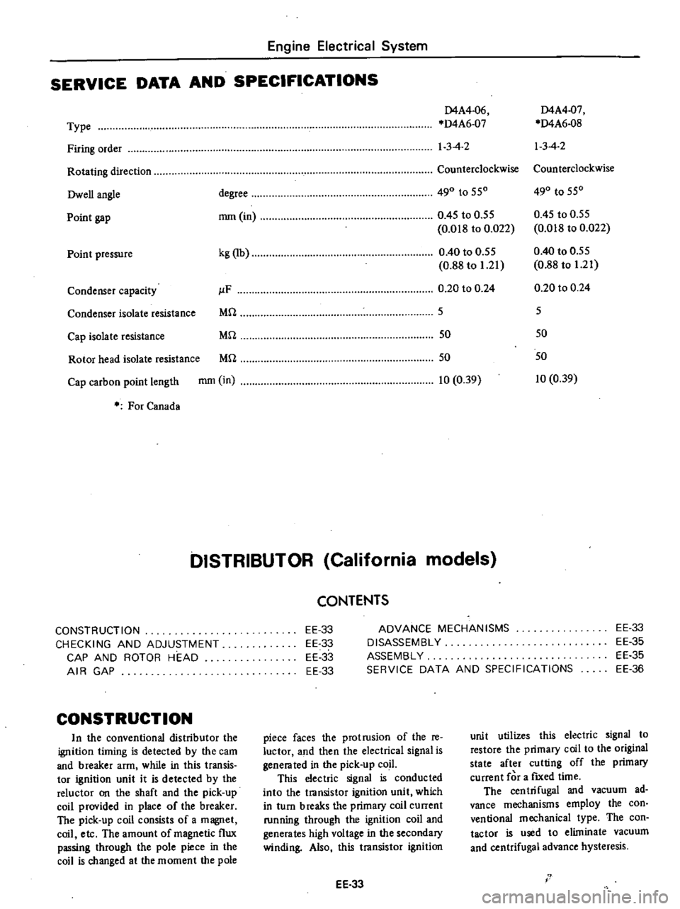
Engine
Electrical
System
SERVICE
DATA
AND
SPECIFICATIONS
D4A4
06
D4A4
07
Type
D4A6
07
D4A6
08
Firing
order
1
3
4
2
13
4
2
Rotating
direction
Counterclockwise
Counterclockwise
Owen
angle
degree
490
to
550
490
to
550
Point
gap
mm
in
0
45
to
0
55
0
45
to
0
55
0
018
to
0
022
0
018
to
0
022
Point
pressure
kg
lb
0
40
to
0
55
0
40
to
0
55
0
88
to
1
21
0
88
to
1
21
Condenser
capacity
JlF
0
20
to
0
24
0
20
to
0
24
Condenser
isolate
resistance
Mrl
5
5
Cap
isolate
resistance
Mrl
50
50
Rotor
head
isolate
resistance
Mrl
50
50
Cap
carbon
point
length
mm
in
10
0
39
10
0
39
For
Canada
DISTRIBUTOR
California
models
CONSTRUCTION
CHECKING
AND
ADJUSTMENT
CAP
AND
ROTOR
HEAD
AIR
GAP
CONSTRUCTION
In
the
conventional
distributor
the
ignition
liming
is
detected
by
the
cam
and
breaker
arm
while
in
this
transis
tor
ignition
unit
it
is
detected
by
the
reluctor
on
the
shaft
and
the
pick
up
coil
provided
in
place
of
the
breaker
The
pick
up
coil
consists
of
a
magnet
coil
etc
The
amount
of
magnetic
flux
passing
through
the
pole
piece
in
the
coil
is
changed
at
the
moment
the
pole
CONTENTS
EE
33
EE
33
EE
33
EE
33
ADVANCE
MECHANISMS
DISASSEMBLY
ASSEMBLY
SERVICE
DATA
AND
SPECIFICATIONS
EE
33
EE
35
EE
35
EE
36
piece
faces
the
protrusion
of
the
re
luctor
and
then
the
electrical
signal
is
genera
ted
in
the
pick
up
coil
This
electric
signal
is
conducted
into
the
transistor
ignition
unit
which
in
turn
breaks
tI
e
primary
coil
current
running
through
the
ignition
coil
and
generates
high
voltage
in
the
secondary
winding
Also
this
transistor
ignition
EE
33
unit
utilizes
this
electric
signal
to
restore
the
primary
coil
to
the
original
state
after
cutting
off
the
primary
current
for
a
fIXed
time
The
centrifugal
and
vacuum
ad
vance
mechanisms
employ
the
con
ventional
mechanical
type
The
con
tactor
is
used
to
eliminate
vacuum
and
centrifugal
advance
hysteresis
I
Page 265 of 537
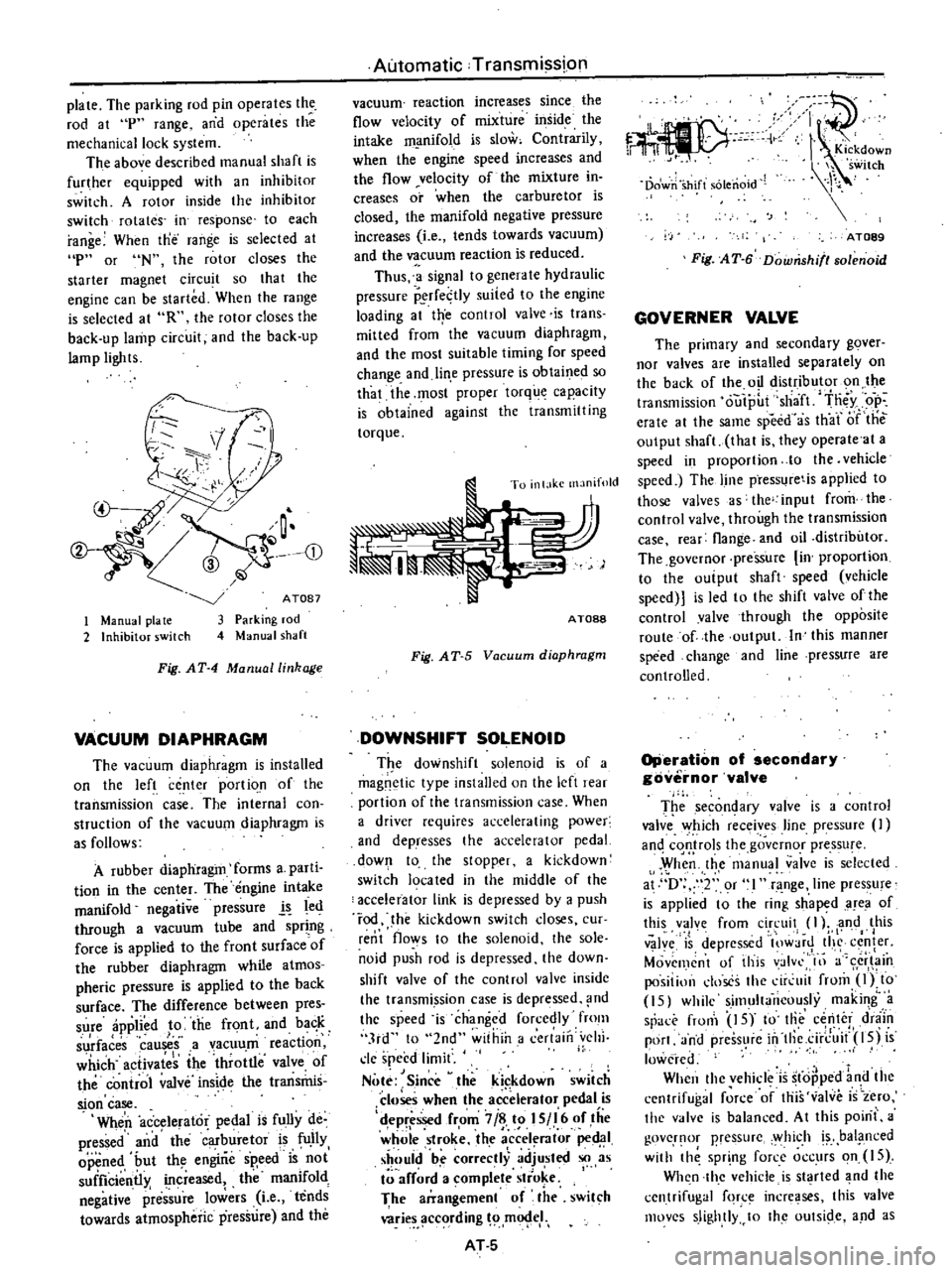
plate
The
parking
rod
pin
operates
the
rod
at
p
range
and
operates
the
mechanical
lock
system
The
above
described
manual
shaft
is
further
equipped
with
an
inhibitor
switch
A
rotor
inside
the
inhibitor
switch
rotates
in
response
to
each
range
When
tne
range
is
selected
at
p
or
N
the
rotor
closes
the
starter
magnet
circuit
so
that
the
engine
can
be
started
When
the
range
is
selected
at
R
the
rolor
closes
the
back
up
lamp
circuit
and
the
back
up
lamp
lights
CD
1
Manual
pia
te
2
Inhibitor
switch
ATOB7
Parking
rod
Manual
shaft
Fig
AT
4
Manual
linkage
VACUUM
DIAPHRAGM
The
vacuum
diaphragm
is
installed
on
the
left
center
portio
n
of
the
transmission
case
The
internal
con
struction
of
the
vacuum
diaphragm
is
as
follows
A
rubber
diaphragm
forms
a
parti
tion
in
the
center
The
engine
intake
manifold
negative
pressure
l
led
through
a
vacuum
tube
and
spring
force
is
applied
to
the
front
surfaceof
the
rubber
diaphragm
while
atmos
pheric
pressure
is
applied
to
the
back
surface
The
difference
between
pres
sure
applied
to
the
front
and
ba
K
I
surfaces
causes
a
vacuum
reactIOn
which
activates
the
throttle
valve
of
the
control
valve
inside
the
transrhis
sion
case
Wheri
accelerator
pedal
is
fully
de
pressed
and
the
buretor
is
fU
IIy
opened
but
th
engirie
sp
eed
is
not
suificientl
increased
the
manifold
negative
plre
sure
lowers
Le
tends
towards
atmospheric
pressure
and
the
Automatic
Transmission
vacuum
reaction
increases
since
the
flow
velocity
of
mixture
inside
the
intake
m
mifold
is
slow
Contrarily
when
the
engine
speed
increases
and
the
flow
velocity
of
the
mixture
in
creases
or
when
the
carburetor
is
closed
the
manifold
negative
pressure
increases
Le
tends
towards
vacuum
and
the
vacuum
reaction
is
reduced
Thus
a
signal
to
genera
Ie
hydraulic
pressure
P
rfe
tly
suited
to
the
engine
loading
at
trye
control
valve
is
trans
mitted
from
the
vacuum
diaphragm
and
the
most
suitable
timing
for
speed
change
and
lin
e
pressure
is
obtaine
so
that
the
most
proper
torque
capacity
is
obtained
against
the
transmitting
torque
To
inl
lkc
manifold
AT088
Fig
AT
5
Vacuum
diaphragm
DOWNSHIFT
SOLENOID
T
e
downshift
solenoid
is
of
a
magnetic
type
installed
on
the
left
re
r
portion
of
the
transmission
case
When
a
driver
requires
accelerating
power
and
dePresses
the
accelerator
pedal
down
to
the
stopper
a
kickdown
switch
19ca
ted
in
the
middle
of
the
accelerator
link
is
depressed
by
a
push
rod
he
kickdown
switch
doses
cur
rent
flows
to
the
solenoid
the
sole
noid
push
rod
is
depressed
the
down
shift
valve
of
the
control
valvc
insidc
the
transmi
ssion
case
is
depressed
nd
the
speed
is
changed
forcedly
fmm
3rd
to
2nd
within
a
cerlaill
vehi
cle
speed
limit
Note
Since
theki
kdown
switch
closes
when
the
accelerator
pedal
is
d
epr
ssed
from
7
i
t
I
S
I
6
of
tiie
whole
stroke
the
a
ccel
rator
ped
1
should
be
correctly
adjusted
so
as
arf
rd
a
omplete
stro
e
I
The
arrangement
of
the
swit
h
wries
ccording
m
eI
AT
S
c
C
r
11
I
Kickdown
h
switch
Dowri
shift
solenoid
AT089
Fig
AT
6
Downshifl80lenoid
GOVERNER
VALVE
The
primary
and
secondary
gover
nor
valves
are
installed
separately
on
the
back
of
the
oil
distributor
on
the
transmission
outp
t
sha
ft
tn
y
op
erate
al
the
same
speed
as
th
ar
iJf
tile
output
shaft
thai
is
they
operate
at
a
speed
in
proportion
10
the
vehicle
speed
The
line
press
retis
applied
to
those
valves
s
the
input
from
the
control
valve
through
the
transmission
case
rear
flange
and
oil
distributor
The
governor
pressure
in
proportion
to
the
ouiput
shaft
speed
vehicle
speed
is
led
to
the
shift
valve
ofthe
control
valve
through
the
opposite
route
of
the
output
In
this
manner
speed
change
and
line
pressure
are
controlled
Operation
of
secondary
governor
valve
T
e
secon
ary
valve
is
a
contro
valve
Y
hich
receives
line
pressure
an
cqQ
rols
the
governor
pressu
e
When
the
manual
valve
is
selected
at
D
2
or
l
range
line
pressure
is
applied
t
the
ri
g
sh
aped
area
of
this
valve
from
circuit
I
l
and
this
I
v
Jy
is
depressed
lOW
jr
tI
c
fer
Movemcnt
of
this
valvl
III
a
cr
in
positillll
doses
the
dr
uit
from
Olto
15
while
simultaneously
making
a
sr
rronl
IS
to
Iii
center
d
niin
port
and
press
re
in
tllc
ci
rJ
it
l5j
is
lowered
When
thc
vehicle
is
stopped
1
d
the
cenlrifugal
force
of
this
valve
is
zero
the
v
lve
is
balanced
At
this
poini
a
govcr
lOr
pressurc
y
hich
bal
i1
nced
with
th
spr
ng
force
occurs
on
IS
Wh
n
thc
vehicle
is
st
rted
nd
the
centrifugal
fqr
incre
ses
this
valve
movcs
slightly
10
Ihc
oUlSide
and
as
Page 269 of 537

3
Jit
f
ng
valve
24
1
3
L
l
r
I
Js
I
i
ilr
t
pressure
6
when
shif
ing
from
3rd
to
2nd
at
D
range
Thus
the
throttle
of
line
pressure
6
reduces
the
shock
generated
fro
shifting
A
plug
in
the
SSV
left
end
readjust
the
throttle
piessu
e
I
6
which
varies
depending
on
the
engine
throttle
con
dition
to
a
throttle
pressure
19
suiled
to
the
sp
ed
change
control
Moreover
the
plug
is
a
valve
which
applies
line
P
esspre
13
in
lieu
of
the
throttle
pressure
to
the
SSV
and
the
FSV
when
kickdowri
is
performed
When
the
throttle
pressure
16
is
applied
to
the
left
side
of
this
plug
and
the
plug
is
epressed
toward
the
right
a
slight
space
is
formed
from
the
throttle
pressure
6
10
19
A
throt
tIepressu
19
w
1iFh
is
lower
by
the
pressure
loss
equivalent
to
this
space
is
rH
1
Pressure
Odifier
valve
PMV
I
Compared
to
the
operating
pressure
required
in
starting
th
vehicle
the
ppwer
trimsinitting
capacity
of
the
clutch
that
is
required
operating
pres
sure
may
be
lower
when
the
vehicle
is
once
started
When
the
line
pressure
is
retained
at
a
high
level
up
to
a
high
vehicle
speed
shock
gerieraled
from
the
shirring
increases
arid
the
oil
pump
loss
also
jncrdases
In
order
to
prevent
his
the
t
lrott
le
pressure
must
be
l
hanged
over
with
the
operation
of
the
governor
pressure
15
to
reduce
Ihe
line
pressure
The
PMV
is
used
for
this
purposc
Automatic
Transmission
generated
the
piessure
loss
is
adde
d
to
the
spring
force
and
the
plug
is
lhus
forced
back
from
the
right
to
the
left
When
this
pressure
19
increases
ex
cessively
the
plug
is
further
depressed
toward
the
left
space
from
the
lhrot
tle
pressure
19
to
the
drain
circuit
13
increases
and
the
throttle
press
ure
19
decreases
Thus
the
plug
is
balanced
imd
the
throttle
pressure
19
is
reduced
to
Ii
certain
value
against
the
throttle
pressure
6
Wheri
performing
kickdowri
the
SDV
moves
a
high
line
pressure
is
led
to
the
circuit
19
from
the
line
pressure
circuit
13
which
had
been
drained
the
plug
is
forced
toward
the
left
and
circuit
19
becomes
equal
to
the
line
pressure
13
I
W
15
I
A
TOgS
Fig
iT
13
2nd
3rd
shift
vallJe
I
When
the
governor
pressuie
IS
which
is
applied
to
the
right
side
of
the
PMV
is
low
the
valve
is
forced
toward
the
right
by
the
throttle
ines
sure
16
applied
to
the
area
differ
ence
of
the
value
and
the
spring
foice
and
t
he
circuit
from
circuit
16
to
circuit
18
is
closed
However
when
vehicle
speed
increases
andl
the
gaver
nor
pressure
15
exceeds
a
certain
level
the
governor
pressure
toward
the
left
which
is
applied
to
the
right
side
exceeds
the
spring
force
and
the
throt
tle
pressure
16
toward
thc
right
the
valve
is
depressed
loward
the
lefi
and
the
throttle
pressure
is
led
from
circuit
AT
9
16
to
circuit
18
This
throttle
pressure
18
is
applied
to
the
top
of
the
PRV
and
the
force
of
the
line
pressure
source
7
is
reduced
Contra
rily
when
the
vehicle
speed
decreases
arid
the
governor
ipressure
15
de
creases
the
force
toward
the
fight
exceeds
ithe
governor
pressure
the
valve
is
forced
back
toward
the
right
and
the
throttle
pressure
18
is
drained
to
the
spring
unit
This
valve
is
sWitched
when
the
throttle
pressure
and
the
governor
pressure
are
high
or
when
tIiey
are
both
Tow
i
i
I
11
18
16
n
r
I
I
15
AT099
Fig
AT
14
Pre
ure
modifier
valve
Vacuum
thro
le
valve
VTV
The
vacuum
t
rottle
valve
is
a
regula
tor
valve
whiCh
uses
the
line
pressure
7
for
the
pressure
source
and
regulates
the
throttle
pressure
16
I
which
is
proportioned
t
the
force
of
the
vacuum
diaphragm
The
vacuum
dia
phragm
yories
depending
on
the
engine
throt
le
condition
negative
pressure
in
the
inta
e
line
When
the
line
pressure
7
is
ap
plied
to
the
bottom
through
the
valve
hole
and
the
v
a
ve
is
forced
upward
space
from
the
line
pressure
7
to
the
throttle
pressure
16
is
dosed
and
the
space
from
the
Ihrottle
pressure
16
to
the
drain
circuit
17
is
about
to
open
In
this
operation
the
throttle
pressure
16
becomes
lower
than
the
linep
s
ureY
btthe
p
e
sur
9
iv
alenl
of
the
loss
of
space
and
Ihe
force
depressing
tlie
rod
if
the
vaeuum
diaphragm
is
balanced
wit
Ii
thethrot
tie
pressure
16
a
pplied
upward
tOlthe
bottom
When
the
erigine
torque
is
high
Ihe
negative
pressure
in
the
intake
iirie
rises
tending
ioward
atmospheric
pressure
and
the
force
of
the
rod
to
depress
the
valve
increases
As
a
result
the
valve
is
depressed
downward
the
Page 323 of 537
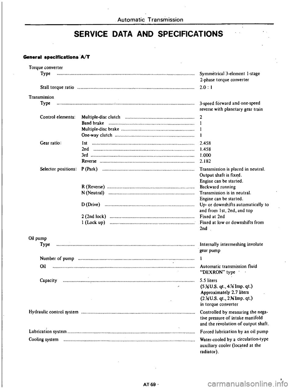
Automatic
Transmission
SERVICE
DATA
AND
SPECIFICATIONS
General
specifications
AfT
Torque
converter
Type
Stall
torque
ratio
Symmetrica13
element
I
stage
2
phase
torque
converter
2
0
I
Transmission
Type
Control
elements
Multiple
disc
clutch
Band
brake
Multiple
disc
brake
One
way
clutch
Gear
ratio
1st
2nd
3rd
Reverse
3
speed
forward
and
one
speed
reverse
with
planetary
gear
train
2
I
I
I
2
458
1458
1
000
2
182
Selector
positions
P
Park
R
Reverse
N
Neutral
Transmission
is
placed
in
neutral
Output
shaft
is
fIXed
Engine
can
be
started
Backward
running
Transmission
is
in
neutral
Engine
can
be
started
Up
or
downshifts
automatically
to
and
from
I
st
2nd
and
top
Fixed
at
2nd
Fixed
at
low
or
downshifts
from
2nd
o
Drive
2
2nd
lock
I
Lock
up
Oil
pump
Type
Internally
intermeshing
involute
gear
pump
Number
of
pump
Oil
Automatic
transmission
fluid
DEXRON
type
5
5
liters
SUU
s
qt
4Ulmp
qt
Approximately
2
7
liters
2UU
s
qt
2XIrnp
qt
in
torque
converter
Controlled
by
measuring
the
nega
tive
pressure
of
intake
manifold
and
the
revolution
of
output
shaft
Forced
lubrication
by
an
oil
pump
Water
cooled
by
a
circulation
type
auxiliary
cooler
located
at
the
radiator
Capacity
Hydraulic
control
system
Lubrication
system
Cooling
system
AT
59