wheel DODGE CHALLENGER 2013 3.G Owner's Manual
[x] Cancel search | Manufacturer: DODGE, Model Year: 2013, Model line: CHALLENGER, Model: DODGE CHALLENGER 2013 3.GPages: 140, PDF Size: 5.35 MB
Page 75 of 140
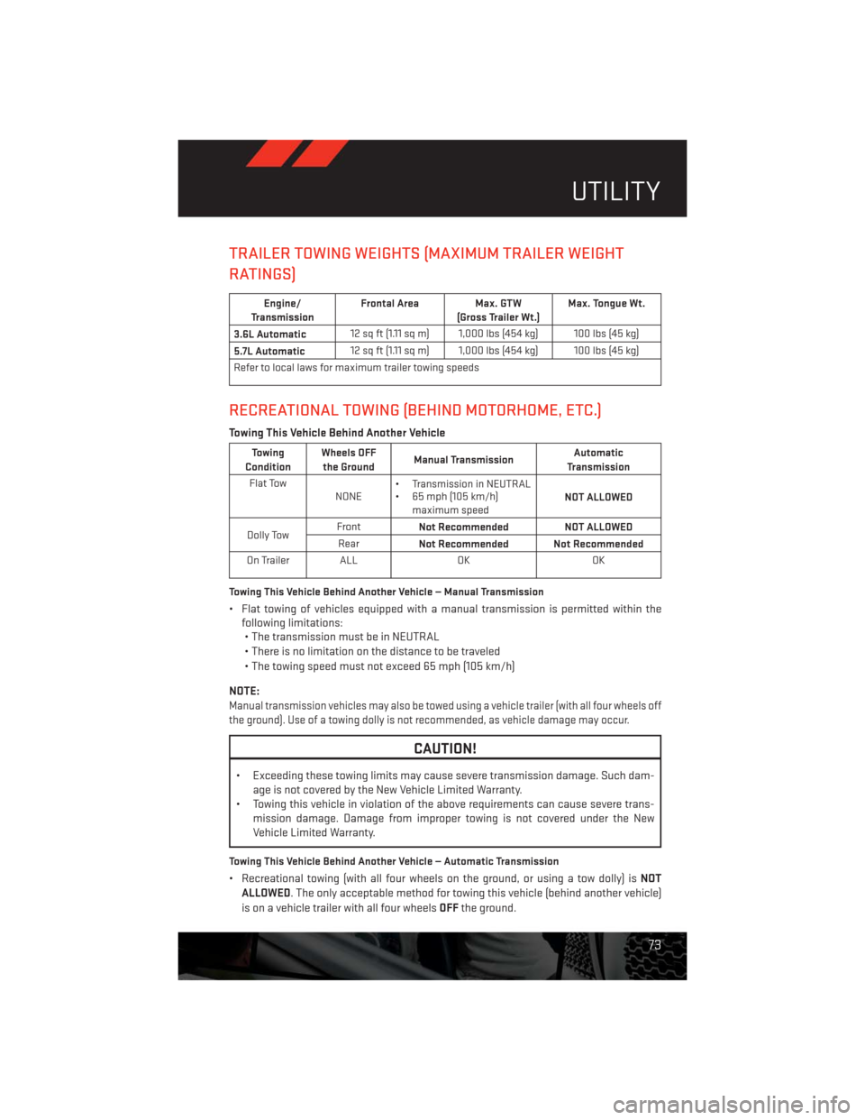
TRAILER TOWING WEIGHTS (MAXIMUM TRAILER WEIGHT
RATINGS)
Engine/
TransmissionFrontal Area Max. GTW
(Gross Trailer Wt.)Max. Tongue Wt.
3.6L Automatic12 sq ft (1.11 sq m) 1,000 lbs (454 kg) 100 lbs (45 kg)
5.7L Automatic12 sq ft (1.11 sq m) 1,000 lbs (454 kg) 100 lbs (45 kg)
Refer to local laws for maximum trailer towing speeds
RECREATIONAL TOWING (BEHIND MOTORHOME, ETC.)
Towing This Vehicle Behind Another Vehicle
Towing
ConditionWheels OFF
the GroundManual TransmissionAutomatic
Transmission
Flat Tow
NONE• Transmission in NEUTRAL
• 65 mph (105 km/h)
maximum speedNOT ALLOWED
Dolly TowFront
Not Recommended NOT ALLOWED
Rear
Not Recommended Not Recommended
On Trailer ALL OK OK
Towing This Vehicle Behind Another Vehicle — Manual Transmission
• Flat towing of vehicles equipped with a manual transmission is permitted within the
following limitations:
• The transmission must be in NEUTRAL
• There is no limitation on the distance to be traveled
• The towing speed must not exceed 65 mph (105 km/h)
NOTE:
Manual transmission vehicles may also be towed using a vehicle trailer (with all four wheels off
the ground). Use of a towing dolly is not recommended, as vehicle damage may occur.
CAUTION!
• Exceeding these towing limits may cause severe transmission damage. Such dam-
age is not covered by the New Vehicle Limited Warranty.
• Towing this vehicle in violation of the above requirements can cause severe trans-
mission damage. Damage from improper towing is not covered under the New
Vehicle Limited Warranty.
Towing This Vehicle Behind Another Vehicle — Automatic Transmission
• Recreational towing (with all four wheels on the ground, or using a tow dolly) isNOT
ALLOWED. The only acceptable method for towing this vehicle (behind another vehicle)
is on a vehicle trailer with all four wheelsOFFthe ground.
UTILITY
73
Page 76 of 140
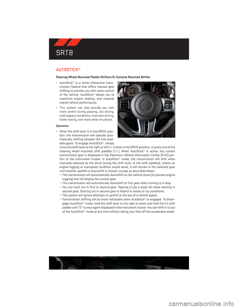
AUTOSTICK®
Steering Wheel Mounted Paddle Shifters Or Console Mounted Shifter
• AutoStick® is a driver-interactive trans-
mission feature that offers manual gear
shifting to provide you with more control
of the vehicle. AutoStick® allows you to
maximize engine braking, and improve
overall vehicle performance.
•
This system can also provide you with
more control during passing, city driving,
cold slippery conditions, mountain driving,
trailer towing, and many other situations.
Operation
• When the shift lever is in the DRIVE posi-
tion, the transmission will operate auto-
matically, shifting between the five avail-
able gears. To engage AutoStick®, simply
move the shift lever to the right or left (+/-) while in the DRIVE position, or press one of the
steering wheel mounted shift paddles (+/-). When AutoStick® is active, the current
transmission gear is displayed in the Electronic Vehicle Information Center (EVIC) por-
tion of the instrument cluster. In AutoStick® mode, the transmission will shift when
manually selected by the driver (using the shift lever, or the shift paddles), unless an
engine lugging or overspeed condition would result. It will remain in the selected gear
until another upshift or downshift is chosen, except as described below:
• The transmission will automatically downshift as the vehicle slows (to prevent engine
lugging) and will display the current gear.
• The transmission will automatically downshift to first gear when coming to a stop.
• You can start out in first or second gear. Tapping (+) (at a stop) will allow starting in
second gear. Starting out in second gear is helpful in snowy or icy conditions.
• The system will ignore attempts to upshift at too low of a vehicle speed.
• Transmission shifting will be more noticeable when AutoStick® is engaged. To disen-
gage AutoStick® mode, hold the shift lever to the right or press and hold the (+) shift
paddle until “D” is once again displayed in the instrument cluster. You can shift in or out
of the AutoStick® mode at any time without taking your foot off the accelerator pedal.
SRT8
74
Page 79 of 140
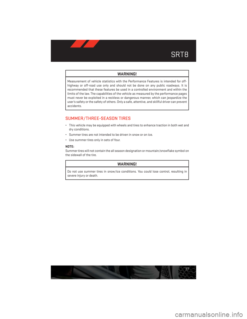
WARNING!
Measurement of vehicle statistics with the Performance Features is intended for off-
highway or off-road use only and should not be done on any public roadways. It is
recommended that these features be used in a controlled environment and within the
limits of the law. The capabilities of the vehicle as measured by the performance pages
must never be exploited in a reckless or dangerous manner, which can jeopardize the
user’s safety or the safety of others. Only a safe, attentive, and skillful driver can prevent
accidents.
SUMMER/THREE-SEASON TIRES
• This vehicle may be equipped with wheels and tires to enhance traction in both wet and
dry conditions.
• Summer tires are not intended to be driven in snow or on ice.
• Use summer tires only in sets of four.
NOTE:
Summer tires will not contain the all season designation or mountain/snowflake symbol on
the sidewall of the tire.
WARNING!
Do not use summer tires in snow/ice conditions. You could lose control, resulting in
severe injury or death.
SRT8
77
Page 81 of 140
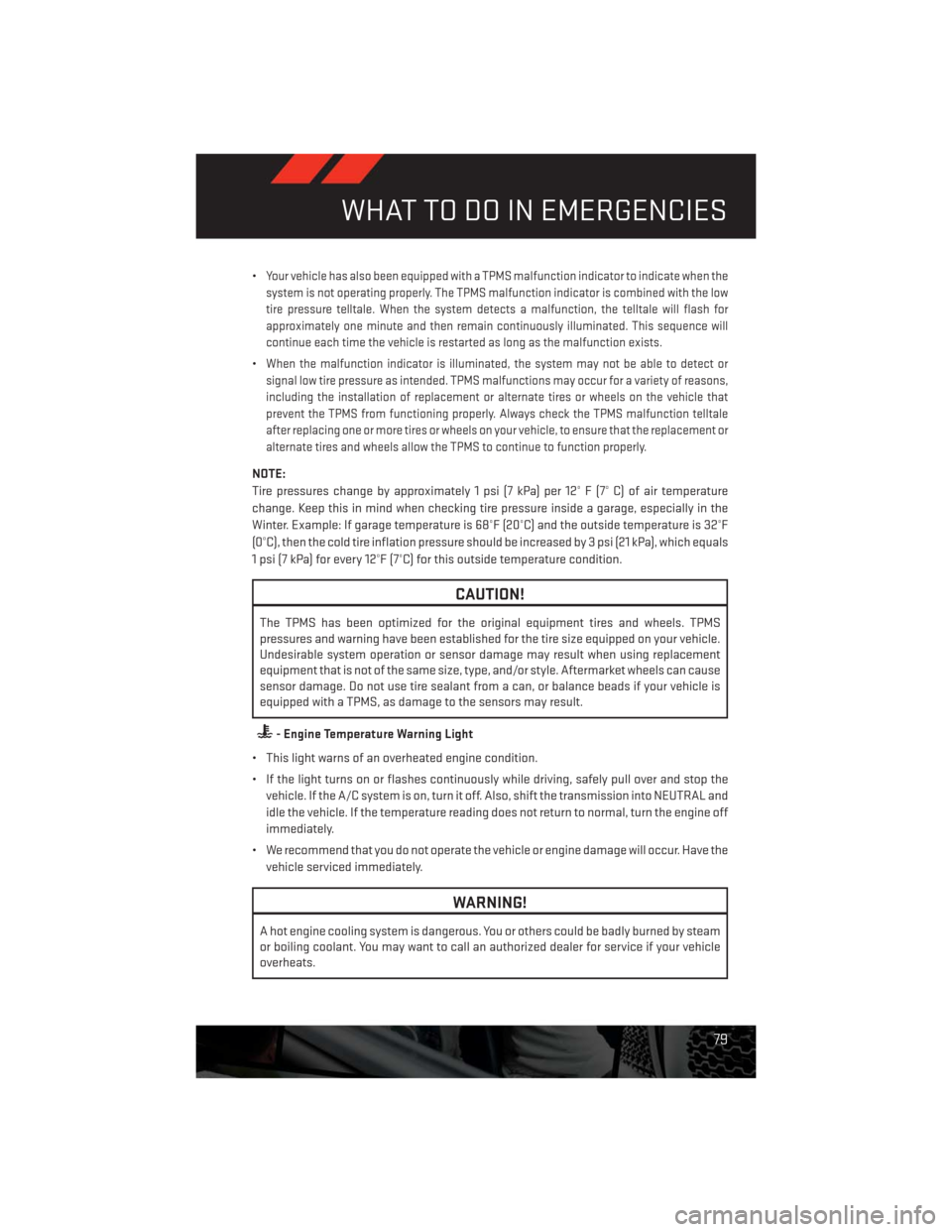
•Your vehicle has also been equipped with a TPMS malfunction indicator to indicate when the
system is not operating properly. The TPMS malfunction indicator is combined with the low
tire pressure telltale. When the system detects a malfunction, the telltale will flash for
approximately one minute and then remain continuously illuminated. This sequence will
continue each time the vehicle is restarted as long as the malfunction exists.
•When the malfunction indicator is illuminated, the system may not be able to detect or
signal low tire pressure as intended. TPMS malfunctions may occur for a variety of reasons,
including the installation of replacement or alternate tires or wheels on the vehicle that
prevent the TPMS from functioning properly. Always check the TPMS malfunction telltale
after replacing one or more tires or wheels on your vehicle, to ensure that the replacement or
alternate tires and wheels allow the TPMS to continue to function properly.
NOTE:
Tire pressures change by approximately 1 psi (7 kPa) per 12° F (7° C) of air temperature
change. Keep this in mind when checking tire pressure inside a garage, especially in the
Winter. Example: If garage temperature is 68°F (20°C) and the outside temperature is 32°F
(0°C), then the cold tire inflation pressure should be increased by 3 psi (21 kPa), which equals
1 psi (7 kPa) for every 12°F (7°C) for this outside temperature condition.
CAUTION!
The TPMS has been optimized for the original equipment tires and wheels. TPMS
pressures and warning have been established for the tire size equipped on your vehicle.
Undesirable system operation or sensor damage may result when using replacement
equipment that is not of the same size, type, and/or style. Aftermarket wheels can cause
sensor damage. Do not use tire sealant from a can, or balance beads if your vehicle is
equipped with a TPMS, as damage to the sensors may result.
- Engine Temperature Warning Light
• This light warns of an overheated engine condition.
• If the light turns on or flashes continuously while driving, safely pull over and stop the
vehicle. If the A/C system is on, turn it off. Also, shift the transmission into NEUTRAL and
idle the vehicle. If the temperature reading does not return to normal, turn the engine off
immediately.
• We recommend that you do not operate the vehicle or engine damage will occur. Have the
vehicle serviced immediately.
WARNING!
A hot engine cooling system is dangerous. You or others could be badly burned by steam
or boiling coolant. You may want to call an authorized dealer for service if your vehicle
overheats.
WHAT TO DO IN EMERGENCIES
79
Page 87 of 140
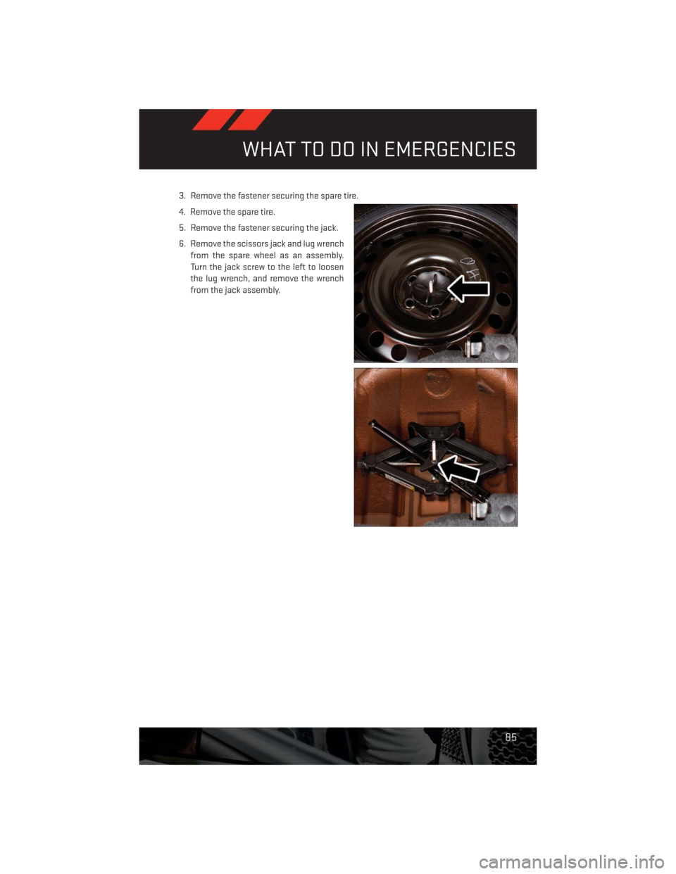
3. Remove the fastener securing the spare tire.
4. Remove the spare tire.
5. Remove the fastener securing the jack.
6. Remove the scissors jack and lug wrench
from the spare wheel as an assembly.
Turn the jack screw to the left to loosen
the lug wrench, and remove the wrench
from the jack assembly.
WHAT TO DO IN EMERGENCIES
85
Page 88 of 140
Preparations For Jacking
1. Park the vehicle on a firm, level surface as far from the edge of the roadway as possible.
Avoid icy or slippery areas.
2. Turn on the Hazard Warning flasher.
3. Set the parking brake.
4. Place the shift lever into PARK.
5. Turn OFF the ignition.
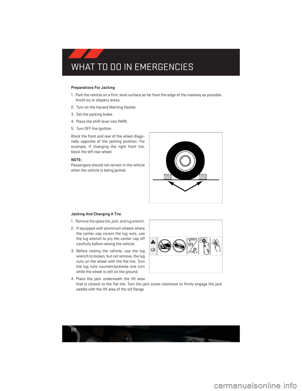
Block the front and rear of the wheel diago-
nally opposite of the jacking position. For
example, if changing the right front tire,
block the left rear wheel.
NOTE:
Passengers should not remain in the vehicle
when the vehicle is being jacked.
Jacking And Changing A Tire
1.
Remove the spare tire, jack, and lug wrench.
2. If equipped with aluminum wheels where
the center cap covers the lug nuts, use
the lug wrench to pry the center cap off
carefully before raising the vehicle.
3. Before raising the vehicle, use the lug
wrench to loosen, but not remove, the lug
nuts on the wheel with the flat tire. Turn
the lug nuts counterclockwise one turn
while the wheel is still on the ground.
4. Place the jack underneath the lift area
that is closest to the flat tire. Turn the jack screw clockwise to firmly engage the jack
saddle with the lift area of the sill flange.
WHAT TO DO IN EMERGENCIES
86
Page 89 of 140
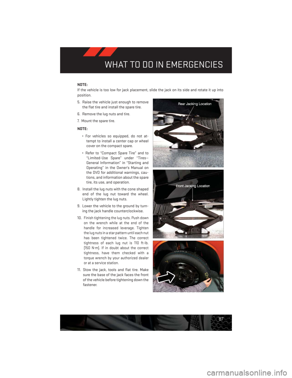
NOTE:
If the vehicle is too low for jack placement, slide the jack on its side and rotate it up into
position.
5. Raise the vehicle just enough to remove
the flat tire and install the spare tire.
6. Remove the lug nuts and tire.
7. Mount the spare tire.
NOTE:
• For vehicles so equipped, do not at-
tempt to install a center cap or wheel
cover on the compact spare.
• Refer to “Compact Spare Tire” and to
“Limited-Use Spare” under “Tires—
General Information” in “Starting and
Operating” in the Owner's Manual on
the DVD for additional warnings, cau-
tions, and information about the spare
tire, its use, and operation.
8. Install the lug nuts with the cone shaped
end of the lug nut toward the wheel.
Lightly tighten the lug nuts.
9. Lower the vehicle to the ground by turn-
ing the jack handle counterclockwise.
10.
Finish tightening the lug nuts. Push down
on the wrench while at the end of the
handle for increased leverage. Tighten
the lug nuts in a star pattern until each nut
has been tightened twice. The correct
tightness of each lug nut is 110 ft-lb.
(150 N·m). If in doubt about the correct
tightness, have them checked with a
torque wrench by your authorized dealer
or at a service station.
11. Stow the jack, tools and flat tire. Make
sure the base of the jack faces the front
of the vehicle before tightening down the
fastener.
WHAT TO DO IN EMERGENCIES
87
Page 90 of 140
Road Tire Installation
1. Mount the road tire on the axle.
2. Install the remaining lug nuts with the cone shaped end of the nut toward the wheel.
Lightly tighten the lug nuts.
3. Lower the vehicle to the ground by turning the jack handle counterclockwise.
4. Finish tightening the lug nuts. Push down on the wrench while at the end of the handle for
increased leverage. Tighten the lug nuts in a star pattern until each nut has been
tightened twice. The correct tightness of each lug nut is 110 ft-lbs (150 N·m). If in doubt
about the correct tightness, have them checked with a torque wrench by your authorized
dealer or service station.
5. After 25 miles (40 km) check the lug nut torque with a torque wrench to ensure that all lug
nuts are properly seated against the wheel.
CAUTION!
Do not attempt to raise the vehicle by jacking on locations other than those indicated in
the Jacking Instructions for this vehicle.
WHAT TO DO IN EMERGENCIES
88
Page 91 of 140
WARNING!
• Do not attempt to change a tire on the side of the vehicle close to moving traffic. Pull
far enough off the road to avoid the danger of being hit when operating the jack or
changing the wheel.
• Being under a jacked-up vehicle is dangerous. The vehicle could slip off the jack and
fall on you. You could be crushed. Never put any part of your body under a vehicle that
is on a jack.
• Never start or run the engine while the vehicle is on a jack. If you need to get under a
raised vehicle, take it to a service center where it can be raised on a lift.
• The jack is designed to be used as a tool for changing tires only. The jack should not
be used to lift the vehicle for service purposes. The vehicle should be jacked on a firm
level surface only. Avoid ice or slippery areas.
• A loose tire or jack thrown forward in a collision or hard stop could endanger the
occupants of the vehicle. Always stow the jack parts and the spare tire in the places
provided.
• Carefully follow these tire changing warnings to help prevent personal injury or
damage to your vehicle:
• Always park on a firm, level surface as far from the edge of the roadway as possible
before raising the vehicle.
• Turn on the Hazard Warning flasher.
• Block the wheel diagonally opposite the wheel to be raised.
• Set the parking brake firmly and set an automatic transmission in PARK; a manual
transmission in REVERSE.
• Do not let anyone sit in the vehicle when it is on a jack.
• Do not get under the vehicle when it is on a jack.
• Only use the jack in the positions indicated and for lifting this vehicle during a tire
change.
• If working on or near a roadway, be extremely careful of motor traffic.
• Raising the vehicle higher than necessary can make the vehicle less stable. It could
slip off the jack and hurt someone near it. Raise the vehicle only enough to remove
the tire.
• To avoid the risk of forcing the vehicle off the jack, do not fully tighten the wheel nuts
until the vehicle has been lowered. Failure to follow this warning may result in
personal injury.
• A loose tire or jack thrown forward in a collision or hard stop could endanger the
occupants of the vehicle. Always stow the jack parts and the spare tire in the places
provided.
• The limited-use spare tires are for emergency use only. Installation of this limited-
use spare tire affects vehicle handling. With this tire, do not drive more than 60 mph
(100 km/h). Keep inflated to the cold tire inflation pressure listed on either your tire
placard or limited-use spare tire and wheel assembly. Replace (or repair) the original
tire at the first opportunity and reinstall it on your vehicle. Failure to do so could result
in loss of vehicle control.
WHAT TO DO IN EMERGENCIES
89
Page 93 of 140
Using The Power Button
• Push and release the Power Button (4) once to turn On the TIREFIT kit. Push and release
the Power Button (4) again to turn Off the TIREFIT kit.
Using The Deflation Button
• Press the Deflation Button (2) to reduce the air pressure in the tire if it becomes
over-inflated.
TIREFIT Usage Precautions
• Replace the TIREFIT Sealant Bottle (1) and Sealant Hose (6) prior to the expiration date
(printed on the bottle label) to assure optimum operation of the system. Refer to “Sealing
a Tire with TIREFIT” section (F) “Sealant Bottle and Hose Replacement”.
• The Sealant Bottle (1) and Sealant Hose (6) are a one tire application use. After each use,
always replace these components immediately at an authorized dealer.
• When the TIREFIT sealant is in a liquid form, clean water, and a damp cloth will remove
the material from the vehicle or tire and wheel components. Once the sealant dries, it can
easily be peeled off and properly discarded.
• For optimum performance, make sure the valve stem on the wheel is free of debris before
connecting the TIREFIT kit.
• You can use the TIREFIT air pump to inflate bicycle tires. The kit also comes with two
needles, located in the Accessory Storage Compartment (on the bottom of the air pump)
for inflating sport balls, rafts, or similar inflatable items. However, use only the Air Pump
Hose (7) and make sure the Mode Select Knob (5) is in the Air Mode when inflating such
items to avoid injecting sealant into them. The TIREFIT Sealant is only intended to seal
punctures less than 1/4 in (6 mm) diameter in the tread of your vehicle.
• Do not lift or carry the TIREFIT kit by the hoses.
Sealing A Tire With TIREFIT
(A) Whenever You Stop To Use TIREFIT:
1. Pull over to a safe location and turn on the vehicle’s Hazard Warning flashers.
2. Verify that the valve stem (on the wheel with the deflated tire) is in a position that is near
to the ground. This will allow the TIREFIT Hoses (6) and (7) to reach the valve stem and
keep the TIREFIT kit flat on the ground. This will provide the best positioning of the kit
when injecting the sealant into the deflated tire and running the air pump. Move the
vehicle as necessary to place the valve stem in this position before proceeding.
3. Place the transmission in PARK (auto transmission) or in Gear (manual transmission)
and cycle the ignition to the OFF position.
4. Set the parking brake.
WHAT TO DO IN EMERGENCIES
91