sensor DODGE CHALLENGER 2015 3.G Owner's Manual
[x] Cancel search | Manufacturer: DODGE, Model Year: 2015, Model line: CHALLENGER, Model: DODGE CHALLENGER 2015 3.GPages: 603, PDF Size: 14.97 MB
Page 260 of 603

status, press the “Off,” “Lights,” or “Lights & Chime”
button on the touchscreen. Then press the back arrow/
Done button on the touchscreen.
NOTE:If your vehicle has experienced any damage in
the area where the sensor is located, even if the fascia is
not damaged, the sensor may have become misaligned.
Take your vehicle to an authorized dealer to verify sensor
alignment. Having a sensor that is misaligned will result
in the BSM not operating to specification.
•ParkView® Backup Camera Active Guidelines
Your vehicle may be equipped with the ParkView® Rear
Back Up Camera Active Guidelines that allows you to see
active guidelines over the ParkView Back up camera
display whenever the shift lever/gear selector is put into
REVERSE. The image will be displayed on the radio
touchscreen display along with a caution note to “check
entire surroundings” across the top of the screen. After
five seconds, this note will disappear. To enable or
disable, press the “ParkView® Backup Camera Active
Guidelines” button on the touchscreen, and select “On”
or “Off.” Press the back arrow/Done button on the
touchscreen to return to the previous menu.
•ParkView® Backup Camera Delay
When the vehicle is shifted out of REVERSE (with camera
delay turned OFF), the rear camera mode is exited and
the navigation or audio screen appears again. When the
vehicle is shifted out of REVERSE (with camera delay
turned ON), the rear view image with dynamic grid lines
will be displayed for up to 10 seconds after shifting out of
“REVERSE” unless the forward vehicle speed exceeds
8 mph (12 km/h), the transmission is shifted into PARK
or the ignition is switched to the OFF position. To set the
ParkView® Backup Camera Delay press the “Controls”
button on the touchscreen, the “settings” button on the
touchscreen, then the “Safety & Assistance” button on the
258 UNDERSTANDING YOUR INSTRUMENT PANEL
Page 266 of 603

10 minutes after the ignition is cycled to OFF. Opening
either front door will cancel this feature. To change the
Engine Off Power Delay status press the “Engine Off
Power Delay” button and select from “0 seconds,” “45
seconds,” “5 minutes” or “10 minutes” buttons on the
touchscreen. Press the back arrow/Done button on the
touchscreen to return to the previous menu.
Compass Settings — If Equipped
After pressing the “Compass Settings” button on the
touchscreen the following settings will be available:
•Variance
Compass Variance is the difference between Magnetic
North and Geographic North. To compensate for the
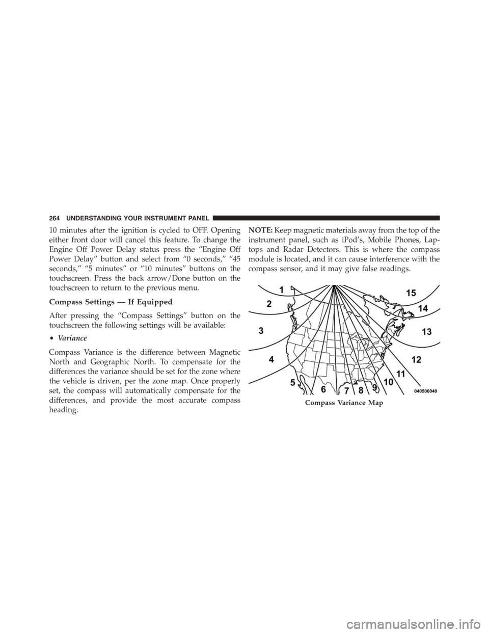
differences the variance should be set for the zone where
the vehicle is driven, per the zone map. Once properly
set, the compass will automatically compensate for the
differences, and provide the most accurate compass
heading.
NOTE:Keep magnetic materials away from the top of the
instrument panel, such as iPod’s, Mobile Phones, Lap-
tops and Radar Detectors. This is where the compass
module is located, and it can cause interference with the
compass sensor, and it may give false readings.
Compass Variance Map
264 UNDERSTANDING YOUR INSTRUMENT PANEL
Page 278 of 603

Blind Spot Alert status, press the “Off,” “Lights” or
“Lights & Chime” button on the touchscreen. Then press
the back arrow button on the touchscreen.
NOTE:If your vehicle has experienced any damage in
the area where the sensor is located, even if the fascia is
not damaged, the sensor may have become misaligned.
Take your vehicle to an authorized dealer to verify sensor
alignment. Having a sensor that is misaligned will result
in the BSM not operating to specification.
•ParkView® Backup Camera Active Guidelines
Your vehicle may be equipped with the ParkView® Rear
Back Up Camera Active Guidelines that allows you to see
active guidelines over the ParkView Back up camera
display whenever the shift lever is put into REVERSE.
The image will be displayed on the radio touchscreen
display along with a caution note to “check entire sur-
roundings” across the top of the screen. After five sec-
onds, this note will disappear. To make your selection,
press the “ParkView Backup Camera Active Guidelines”
button on the touchscreen, until a check-mark appears
next to setting, indicating that the setting had been
selected. Press the back arrow button on the touchscreen
to return to the previous menu.
•ParkView® Backup Camera Delay
When the vehicle is shifted out of REVERSE (with camera
delay turned OFF), the rear camera mode is exited and
the navigation or audio screen appears again. When the
vehicle is shifted out of REVERSE (with camera delay
turned ON), the rear view image with dynamic grid lines
will be displayed for up to 10 seconds after shifting out of
“REVERSE” unless the forward vehicle speed exceeds
8 mph (12 km/h), the transmission is shifted into
“PARK” or the ignition is switched to the OFF position.
To set the ParkView® Backup Camera Delay press the
“Controls” button on the touchscreen, the “settings”
button on the touchscreen, then the “Safety & Driving
276 UNDERSTANDING YOUR INSTRUMENT PANEL
Page 297 of 603

When G-Force is selected, the following features will be
available:
•Lateral G-Force Left and Right
The lateral g-force measures the (sideways) left and right
force of the vehicle.
•Longitudinal G-Force Fore and Aft
The longitudinal g-force measures the acceleration and
braking force of the vehicle.
•Peak G-Forces Fore Aft, Left and Right
This shows the maximum g-forces that have been
achieved since the last reset from the DID. Peak values
are maintained through ignition cycles by the DID until
they are cleared by the driver.
•Vehicle Speed
Vehicle Speed measures the current speed of the vehicle
in either mph or km/h, starting at 0 with no maximum
value.
•Steering Wheel Angle
Steering Wheel Angle utilizes the steering angle sensor to
measure the degree of the steering wheel relative to zero.
The zero degree measurement indicates a steering wheel
straight ahead position. When the steering angle value is
negative, this indicates a turn to the left, and when the
steering angle value is positive, a turn to the right.
4
UNDERSTANDING YOUR INSTRUMENT PANEL 295
Page 389 of 603

by applying the brake of the appropriate wheel. Engine
power may also be reduced to assist in counteracting the
condition of oversteer or understeer and help the vehicle
maintain the desired path.
The ESC uses sensors in the vehicle to determine the path
that the driver intends to steer the vehicle and compares
it to the actual path of the vehicle. When the actual path
does not match the intended path, the ESC applies the
brake of the appropriate wheel to assist in counteracting
the condition of oversteer or understeer.
•Oversteer - when the vehicle is turning more than
appropriate for the steering wheel position.
•Understeer - when the vehicle is turning less than
appropriate for the steering wheel position.
WARNING!
The Electronic Stability Control System (ESC) cannot
prevent the natural laws of physics from acting on
the vehicle, nor can it increase the traction afforded
by prevailing road conditions. ESC cannot prevent
all accidents, including those resulting from exces-
sive speed in turns, driving on very slippery surfaces,
or hydroplaning. ESC also cannot prevent accidents
resulting from loss of vehicle control due to inappro-
priate driver input for the conditions. Only a safe,
attentive, and skillful driver can prevent accidents.
The capabilities of an ESC equipped vehicle must
never be exploited in a reckless or dangerous manner
which could jeopardize the user ’s safety or the safety
of others.
5
STARTING AND OPERATING 387
Page 421 of 603

For example, your vehicle may have a recommended
cold (parked for more than three hours) placard pressure
of 30 psi (207 kPa). If the ambient temperature is 68°F
(20°C) and the measured tire pressure is 27 psi (186 kPa),
a temperature drop to 20°F (-7°C) will decrease the tire
pressure to approximately 23 psi (158 kPa). This tire
pressure is sufficiently low enough to turn ON the “TPM
Telltale Light.” Driving the vehicle may cause the tire
pressure to rise to approximately 27 psi (186 kPa), but the
“TPM Telltale Light” will still be ON. In this situation, the
“TPM Telltale Light” will turn OFF only after the tires are
inflated to the vehicle’s recommended cold placard pres-
sure value.
CAUTION!
•The TPMS has been optimized for the original
equipment tires and wheels. TPMS pressures and
warning have been established for the tire size
equipped on your vehicle. Undesirable system op-
eration or sensor damage may result when using
replacement equipment that is not of the same size,
type, and/or style. Aftermarket wheels can cause
sensor damage. Using aftermarket tire sealants may
cause the Tire Pressure Monitoring System (TPMS)
sensor to become inoperable. After using an after-
market tire sealant it is recommended that you take
your vehicle to your local dealer to have your
sensor function checked.
•After inspecting or adjusting the tire pressure,
always reinstall the valve stem cap. This will
prevent moisture and dirt from entering the valve
stem, which could damage the TPM sensor.
5
STARTING AND OPERATING 419
Page 423 of 603

Premium System
The Tire Pressure Monitor System (TPMS) uses wireless
technology with wheel rim mounted electronic sensors to
monitor tire pressure levels. Sensors mounted to each
wheel as part of the valve stem transmit tire pressure
readings to the receiver module.
NOTE:It is particularly important for you to check the
tire pressure in all of the tires on your vehicle monthly
and to maintain the proper pressure.
The TPMS consists of the following components:
•Receiver module,
•Four TPM sensors,
•Various TPMS messages, which display in the Driver
Information Display (DID), and
•TPM Telltale Light
Tire Pressure Monitoring Low Pressure Warnings
The “TPM Telltale Light” will illuminate in the
instrument cluster and a chime will sound when
tire pressure is low in one or more of the four active road
tires. In addition, the DID will display a “LOW TIRE”
message and a graphic showing the pressure values ofTire Pressure Monitor Display
5
STARTING AND OPERATING 421
Page 424 of 603

each tire with the low tire pressure values shown in a
different color. An#Inflate Tire to XX#message will also
be displayed in the DID display.
Should this occur, you should stop as soon as possible
and inflate all of the tires with a low pressure condition
(those shown in a different color in the DID graphic) to
the vehicle’s recommended cold placard pressure infla-
tion value as shown in the#Inflate Tire to XX#message.
Once the system receives the updated tire pressures, the
system will automatically update, the graphic display in
the DID will return the pressure values to shown their
original color, and the pressure values shown in the
“TPM Telltale Light” will turn off. The vehicle may need
to be driven for up to 20 minutes above 15 mph
(24 km/h) in order for the TPMS to receive this informa-
tion.
Service TPMS Warning
If a system fault is detected, the “TPM Telltale Light” will
flash on and off for 75 seconds and then remain on solid.
The system fault will also sound a chime. In addition, the
DID will display a#SERVICE TPM SYSTEM#message for
a minimum of five seconds and then display dashes (- -)
in place of the pressure value to indicate which sensor is
not being received.
If the ignition switch is cycled, this sequence will repeat,
providing the system fault still exists. If the system fault
no longer exists, the “TPM Telltale Light” will no longer
flash, and the#SERVICE TPM SYSTEM#message will no
longer display, and a pressure value will display in place
of the dashes. A system fault can occur due to any of the
following:
1. Signal interference due to electronic devices or driving
next to facilities emitting the same radio frequencies as
the TPM sensors.
422 STARTING AND OPERATING
Page 425 of 603

2. Installing aftermarket window tinting that contains
materials that may block radio wave signals.
3. Accumulation of snow or ice around the wheels or
wheel housings.
4. Using tire chains on the vehicle.
5. Using wheels/tires not equipped with TPM sensors.
The DID will also display a#SERVICE TPM SYSTEM#
message for a minimum of five seconds when a system
fault related to an incorrect sensor location fault is
detected. In this case, the#SERVICE TPM SYSTEM#
message is then followed with a graphic display with
pressure values still shown. This indicates that the pres-
sure values are still being received from the TPM sensors
but they may not be located in the correct vehicle
position. The system still needs to be serviced as long as
the#SERVICE TPM SYSTEM#message is displayed.
Vehicles With Compact Spare
1. The compact spare tire does not have a TPM sensor.
Therefore, the TPMS will not monitor the pressure in
the compact spare tire.
2. If you install the compact spare tire in place of a road
tire that has a pressure below the low-pressure warn-
ing limit, upon the next ignition switch cycle, the
“TPM Telltale Light” will remain ON and a chime will
sound. In addition, the graphic in the DID will still
display the low pressure values in a different color and
the#Inflate Tire to XX#message.
3. After driving the vehicle for up to 20 minutes above
15 mph (24 km/h), the “TPM Telltale Light” will flash
on and off for 75 seconds and then remain on solid. In
addition, the DID will display a#SERVICE TPM
SYSTEM#message for a minimum of five seconds and
then display dashes (- -) in place of the pressure value.
5
STARTING AND OPERATING 423
Page 426 of 603

4. For each subsequent ignition switch cycle, a chime will
sound, the “TPM Telltale Light” will flash on and off
for 75 seconds and then remain on solid, and the DID
will display a#SERVICE TPM SYSTEM#message for a
minimum of five seconds and then display dashes (- -)
in place of the pressure value.
5. Once you repair or replace the original road tire and
reinstall it on the vehicle in place of the compact spare,
the TPMS will update automatically. In addition, the
“TPM Telltale Light” will turn OFF and the graphic in
the DID will display a new pressure value instead of
dashes (- -), as long as no tire pressure is below the
low-pressure warning limit in any of the four active
road tires. The vehicle may need to be driven for up to
20 minutes above 15 mph (24 km/h) in order for the
TPMS to receive this information.
General Information
This device complies with Part 15 of the FCC rules and
RSS 210 of Industry Canada. Operation is subject to the
following conditions:
•This device may not cause harmful interference.
•This device must accept any interference received,
including interference that may cause undesired op-
eration.
The TPM sensors are regulated under one of the follow-
ing licenses:
United StatesMRXMERCTX1
Canada2546A-MERCTX1
424 STARTING AND OPERATING