towing DODGE CHALLENGER 2015 3.G Owners Manual
[x] Cancel search | Manufacturer: DODGE, Model Year: 2015, Model line: CHALLENGER, Model: DODGE CHALLENGER 2015 3.GPages: 603, PDF Size: 14.97 MB
Page 120 of 603
vehicle speed reaches approximately 6 mph (10 km/h) or
higher and will alert the driver of vehicles in these areas.
NOTE:
•The BSM system does NOT alert the driver about
rapidly approaching vehicles that are outside the de-
tection zones.
•The BSM system detection zone DOES NOT change if
your vehicle is towing a trailer. Therefore, visually
verify the adjacent lane is clear for both your vehicle
and trailer before making a lane change. If the trailer or
other object (i.e., bicycle, sports equipment) extends
beyond the side of your vehicle, this may result in the
BSM warning light remaining illuminated the entire
time the vehicle is in a forward gear.
The area on the rear fascia where the radar sensors are
located must remain free of snow, ice, and dirt/road
contamination so that the BSM system can function
properly. Do not block the area of the rear fascia where
the radar sensors are located with foreign objects (bum-
per stickers, bicycle racks, etc.).
The BSM system notifies the driver of objects in the
detection zones by illuminating the BSM warning light
located in the outside mirrors in addition to sounding an
audible (chime) alert and reducing the radio volume.
Refer to “Modes Of Operation” for further information.
The BSM system monitors the detection zone from three
different entry points (side, rear, front) while driving to
see if an alert is necessary. The BSM system will issue an
alert during these types of zone entries.
11 8 U N D E R S TA N D I N G T H E F E AT U R E S O F Y O U R V E H I C L E
Page 162 of 603
WARNING!(Continued)
•Cannot take street, traffic, and weather condi-
tions into account, and may be limited upon
adverse sight distance conditions.
•Does not always fully recognize complex driving
conditions, which can result in wrong or missing
distance warnings.
•Will bring the vehicle to a complete stop while
following a target vehicle and hold the vehicle
for 2 seconds in the stop position. If the target
vehicle does not start moving within two seconds
the ACC system will display a message that the
system will release the brakes and that the
brakes must be applied manually. An audible
chime will sound when the brakes are released.
(Continued)
WARNING!(Continued)
You should switch off the ACC system:
When driving in fog, heavy rain, heavy snow, sleet,
heavy traffic, and complex driving situations (i.e., in
highway construction zones).
When entering a turn lane or highway off ramp;
when driving on roads that are winding, icy, snow-
covered, slippery, or have steep uphill or downhill
slopes.
When towing a trailer up or down steep slopes.
When circumstances do not allow safe driving at a
constant speed.
The Cruise Control system has two control modes:
•Adaptive Cruise Control mode for maintaining an
appropriate distance between vehicles.
160 UNDERSTANDING THE FEATURES OF YOUR VEHICLE
Page 177 of 603
If this occurs, try activating ACC again later, following a
key cycle. If the problem persists, see your authorized
dealer.
Precautions While Driving With ACC
In certain driving situations, ACC may have detection
issues. In these cases, ACC may brake late or unexpect-
edly. The driver needs to stay alert and may need to
intervene.
Towing A Trailer
NOTE:Towing a trailer is not advised when using ACC.
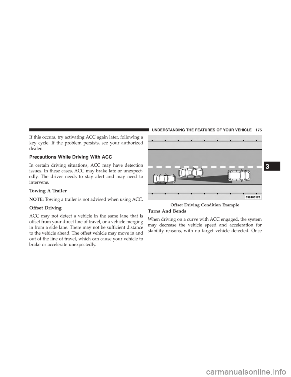
Offset Driving
ACC may not detect a vehicle in the same lane that is
offset from your direct line of travel, or a vehicle merging
in from a side lane. There may not be sufficient distance
to the vehicle ahead. The offset vehicle may move in and
out of the line of travel, which can cause your vehicle to
brake or accelerate unexpectedly.
Turns And Bends
When driving on a curve with ACC engaged, the system
may decrease the vehicle speed and acceleration for
stability reasons, with no target vehicle detected. Once
Offset Driving Condition Example
3
UNDERSTANDING THE FEATURES OF YOUR VEHICLE 175
Page 226 of 603
INSTRUMENT CLUSTER DESCRIPTIONS
1. Tachometer
The red segments indicate the maximum permissible
engine revolutions per minute (RPM x 1000) for each gear
range. Ease up on the accelerator before reaching the red
area.
2. Malfunction Indicator Light (MIL)
The Malfunction Indicator Light (MIL) is part of
an onboard diagnostic system called OBD. The
OBD system monitors engine and automatic
transmission control systems. The MIL will turn on when
the ignition is in the ON/RUN position before engine
start. If the MIL does not come on when turning the key
from OFF to ON/RUN, have the condition checked
promptly.
Certain conditions, such as a loose or missing gas cap,
poor fuel quality, etc., may illuminate the MIL after
engine start. The vehicle should be serviced if the MIL
stays on through several of your typical driving cycles. In
most situations, the vehicle will drive normally and will
not require towing.
CAUTION!
Prolonged driving with the Malfunction Indicator
Light (MIL) on could cause damage to the engine
control system. It also could affect fuel economy and
driveability. If the MIL is flashing, severe catalytic
converter damage and power loss will soon occur.
Immediate service is required.
WARNING!
A malfunctioning catalytic converter, as referenced
above, can reach higher temperatures than in normal
(Continued)
224 UNDERSTANDING YOUR INSTRUMENT PANEL
Page 232 of 603
The gauge pointer will likely indicate a higher tempera-
ture when driving in hot weather, up mountain grades,
or when towing a trailer. It should not be allowed to
exceed the upper limits of the normal operating range.
CAUTION!
Driving with a hot engine cooling system could
damage your vehicle. If the temperature gauge reads
“H,” pull over and stop the vehicle. Idle the vehicle
with the air conditioner turned off until the pointer
drops back into the normal range. If the pointer
remains on the “H,” and you hear a chime, turn the
engine OFF immediately and call for service.
WARNING!
A hot engine cooling system is dangerous. You or
others could be badly burned by steam or boiling
(Continued)
WARNING!(Continued)
coolant. You may want to call a service center if your
vehicle overheats. If you decide to look under the
hood yourself, refer to “Maintaining Your Vehicle”
and follow the warnings under the Cooling System
Pressure Cap paragraph.
17. Tire Pressure Monitoring Telltale Light
Each tire, including the spare (if provided),
should be checked monthly when cold and
inflated to the inflation pressure recommended
by the vehicle manufacturer on the vehicle
placard or tire inflation pressure label. (If your vehicle
has tires of a different size than the size indicated on the
vehicle placard or tire inflation pressure label, you should
determine the proper tire inflation pressure for those
tires.)
230 UNDERSTANDING YOUR INSTRUMENT PANEL
Page 348 of 603
▫6.4L Engine..........................426
▫Reformulated Gasoline.................427
▫Gasoline/Oxygenate Blends..............427
▫E-85 Usage In Non-Flex Fuel Vehicles.......428
▫MMT In Gasoline.....................428
▫Materials Added To Fuel................429
▫Fuel System Cautions...................429
▫Carbon Monoxide Warnings.............430
!ADDING FUEL........................431
▫Fuel Filler Cap (Gas Cap)...............431
▫Loose Fuel Filler Cap Message............433
!VEHICLE LOADING....................433
▫Vehicle Certification Label...............433
▫Gross Vehicle Weight Rating (GVWR).......434
▫Gross Axle Weight Rating (GAWR).........434
▫Overloading.........................434
▫Loading............................435
!TRAILER TOWING.....................435
▫Common Towing Definitions.............436
▫Trailer Hitch Classification...............439
▫Trailer Towing Weights (Maximum Trailer Weight
Ratings)............................440
▫Trailer And Tongue Weight..............440
▫Towing Requirements..................441
▫Towing Tips.........................446
!RECREATIONAL TOWING (BEHIND
MOTORHOME, ETC.)...................448
▫Towing This Vehicle Behind Another Vehicle . .448
346 STARTING AND OPERATING
Page 369 of 603
WARNING!(Continued)
practices that limit your response to changing traffic
or road conditions. You might lose control of the
vehicle and have a collision.
CAUTION!
Towing the vehicle, coasting, or driving for any other
reason with the transmission in NEUTRAL can cause
severe transmission damage. Refer to “Recreational
Towing” in “Starting And Operating” and “Towing A
Disabled Vehicle” in “What To Do In Emergencies”
for further information.
DRIVE (D)
This range should be used for most city and highway
driving. It provides the smoothest upshifts and down-
shifts, and the best fuel economy. The transmission
automatically upshifts through all forward gears. The
DRIVE position provides optimum driving characteris-
tics under all normal operating conditions.
When frequent transmission shifting occurs (such as
when operating the vehicle under heavy loading condi-
tions, in hilly terrain, or traveling into strong head winds,
or while towing heavy trailers), use the AutoStick® shift
control (refer to#AutoStick®#in this section for further
information) to select a lower gear. Under these condi-
tions, using a lower gear will improve performance and
extend transmission life by reducing excessive shifting
and heat buildup.
During extremely cold temperatures (-22°F [-30°C] or
below), transmission operation may be modified depend-
ing on engine and transmission temperature as well as
vehicle speed. Normal operation will resume once the
transmission temperature has risen to a suitable level.
5
STARTING AND OPERATING 367
Page 371 of 603
1. Stop the vehicle.
2. Shift the transmission into PARK, if possible. If not,
shift the transmission to NEUTRAL.
3. Press and hold the ignition switch until the engine
turns OFF.
4. Wait approximately 30 seconds.
5. Restart the engine.
6. Shift into the desired gear range. If the problem is no
longer detected, the transmission will return to normal
operation.
NOTE:Even if the transmission can be reset, we recom-
mend that you visit your authorized dealer at your
earliest possible convenience. Your authorized dealer has
diagnostic equipment to determine if the problem could
recur.
If the transmission cannot be reset, authorized dealer
service is required.
AUTOSTICK®
AutoStick® is a driver-interactive transmission feature
providing manual shift control, giving you more control
of the vehicle. AutoStick® allows you to maximize en-
gine braking, eliminate undesirable upshifts and down-
shifts, and improve overall vehicle performance. This
system can also provide you with more control during
passing, city driving, cold slippery conditions, mountain
driving, trailer towing, and many other situations.
Operation
When the shift lever is in the DRIVE (D) position, the
transmission will operate automatically, shifting between
the eight available gears. To activate AutoStick®, move
the shift lever into the MANUAL (M) position (beside the
DRIVE position). The current transmission gear will be
5
STARTING AND OPERATING 369
Page 402 of 603
3. Tire size designed for your vehicle.
4. Cold tire inflation pressures for the front, rear, and
spare tires.
Loading
The vehicle maximum load on the tire must not exceed
the load carrying capacity of the tire on your vehicle. You
will not exceed the tire’s load carrying capacity if you
adhere to the loading conditions, tire size, and cold tire
inflation pressures specified on the Tire and Loading
Information placard and in the “Vehicle Loading” section
of this manual.
NOTE:Under a maximum loaded vehicle condition,
gross axle weight ratings (GAWRs) for the front and rear
axles must not be exceeded. For further information on
GAWRs, vehicle loading, and trailer towing, refer to
“Vehicle Loading” in this section.
To determine the maximum loading conditions of your
vehicle, locate the statement “The combined weight of
occupants and cargo should never exceed XXX lbs or
XXX kg” on the Tire and Loading Information placard.
The combined weight of occupants, cargo/luggage and
trailer tongue weight (if applicable) should never exceed
the weight referenced here.
Steps For Determining Correct Load Limit
1. Locate the statement “The combined weight of occu-
pants and cargo should never exceed XXX lbs or
XXX kg” on your vehicle’s placard.
2. Determine the combined weight of the driver and
passengers that will be riding in your vehicle.
3. Subtract the combined weight of the driver and pas-
sengers from XXX lbs or XXX kg.
400 STARTING AND OPERATING
Page 403 of 603
4. The resulting figure equals the available amount of
cargo and luggage load capacity. For example, if
“XXX” amount equals 1,400 lbs (635 kg) and there will
be five 150 lb (68 kg) passengers in your vehicle, the
amount of available cargo and luggage load capacity
is 650 lbs (295 kg) (since 5 x 150 lbs (68 kg) = 750 lbs
(340 kg), and 1400 lbs (635 kg) – 750 lbs (340 kg) =
650 lbs [295 kg]).
5. Determine the combined weight of luggage and cargo
being loaded on the vehicle. That weight may not
safely exceed the available cargo and luggage load
capacity calculated in step 4.
NOTE:
•If your vehicle will be towing a trailer, load from your
trailer will be transferred to your vehicle. The follow-
ing table shows examples on how to calculate total
load, cargo/luggage, and towing capacities of your
vehicle with varying seating configurations and num-
ber and size of occupants. This table is for illustration
purposes only and may not be accurate for the seating
and load carry capacity of your vehicle.
•For the following example, the combined weight of
occupants and cargo should never exceed 865 lbs
(392 kg).
5
STARTING AND OPERATING 401