check engine DODGE CHALLENGER 2020 Owners Manual
[x] Cancel search | Manufacturer: DODGE, Model Year: 2020, Model line: CHALLENGER, Model: DODGE CHALLENGER 2020Pages: 396, PDF Size: 16.64 MB
Page 6 of 396
4
OCCUPANT RESTRAINT SYSTEMS .................. 111 Occupant Restraint Systems Features ....111
Important Safety Precautions ...................111Seat Belt Systems ..................................... 112Supplemental Restraint Systems (SRS) ...120Child Restraints .........................................130
Transporting Pets.......................................145
SAFETY TIPS ....................................................... 145
Transporting Passengers ..........................145
Exhaust Gas ........................................... 145
Safety Checks You Should Make Inside
The Vehicle ................................................146 Periodic Safety Checks You Should
Make Outside The Vehicle ........................ 147
STARTING AND OPERATING
STARTING THE ENGINE .................................. 148
Manual Transmission — If Equipped ........148Automatic Transmission — If Equipped ....148
Normal Starting ......................................149
Cold Weather Operation
(Below –22°F Or −30°C) .........................151 If Engine Fails To Start .............................. 152
After Starting ..............................................152
ENGINE BLOCK HEATER — IF EQUIPPED ........ 152
ENGINE BREAK-IN RECOMMENDATIONS —
3.6L & 5.7L ....................................................... 152 ENGINE BREAK-IN RECOMMENDATIONS —
6.2L & 6.4L ......................................................... 153
PARKING BRAKE ................................................ 154
MANUAL TRANSMISSION — IF EQUIPPED ...... 155
Six-Speed Manual Transmission .............. 155
Shifting ....................................................... 156Recommended Shift Speeds .................... 157
1–4 Skip Shift ........................................... 158
Downshifting .............................................. 158
AUTOMATIC TRANSMISSION —
IF EQUIPPED ...................................................... 158
Ignition Park Interlock ............................... 159Brake/Transmission Shift Interlock
System ....................................................... 160 Eight-Speed Automatic Transmission ...... 160
SPORT MODE — WITHOUT PERFORMANCE
CONTROL............................................................. 165
FUEL SAVER TECHNOLOGY 5.7L AND 6.4L
ONLY — IF EQUIPPED......................................... 166
ELECTRIC POWER STEERING ........................... 166
SPEED CONTROL — IF EQUIPPED .................... 166 To Activate ................................................ 167
To Set A Desired Speed ............................ 167
To Vary The Speed Setting ....................... 167
To Accelerate For Passing ........................ 168
To Resume Speed .................................... 168
To Deactivate ............................................ 168 ADAPTIVE CRUISE CONTROL (ACC) —
IF EQUIPPED .................................................... 169
Adaptive Cruise Control (ACC)
Operation ................................................... 170 Activating Adaptive Cruise Control
(ACC) ........................................................... 171 To Activate/Deactivate.............................. 171
To Set A Desired ACC Speed..................... 171
To Cancel ................................................... 172
To Turn Off ................................................. 172To Resume ................................................. 172To Vary The Speed Setting ........................ 172
Setting The Following Distance In ACC .... 174
Overtake Aid............................................... 175
Adaptive Cruise Control (ACC) Menu ........ 175
Display Warnings And Maintenance ........ 175
Precautions While Driving With ACC......... 176
General Information .................................. 179
Normal (Fixed Speed) Cruise Control
Mode .......................................................... 179
PARKSENSE REAR PARK ASSIST —
IF EQUIPPED ....................................................... 181
ParkSense Sensors ................................... 181
ParkSense Warning Display...................... 181
ParkSense Display..................................... 182
Enabling And Disabling ParkSense .......... 185Service The ParkSense Rear Park Assist
System........................................................ 185 Cleaning The ParkSense System.............. 185
ParkSense System Usage Precautions .... 185
20_LA_OM_EN_USC_t.book Page 4
Page 7 of 396
5
PARKVIEW REAR BACK UP CAMERA ............. 186
REFUELING THE VEHICLE ................................. 188 Loose Fuel Filler Cap Message ................. 188
VEHICLE LOADING .......................................... 189
Vehicle Certification Label .......................189
Gross Vehicle Weight Rating (GVWR) ......189Gross Axle Weight Rating (GAWR) ........... 189Overloading ................................................189
Loading ....................................................190
TRAILER TOWING ............................................. 190
Common Towing Definitions .....................190Trailer Hitch Classification ........................ 191Trailer Towing Weights (Maximum
Trailer Weight Ratings) ............................192 Trailer And Tongue Weight .......................193
Towing Requirements ................................193Towing Tips ................................................196
RECREATIONAL TOWING
(BEHIND MOTORHOME, ETC.) .......................... 197
DRIVING TIPS ..................................................... 197
Driving On Slippery Surfaces.....................197Driving Through Water .............................. 197
IN CASE OF EMERGENCY
HAZARD WARNING FLASHERS ..................... 199
ASSIST AND SOS MIRROR — IF EQUIPPED.... 199
General Information ..................................203 BULB REPLACEMENT ........................................ 204
Replacement Bulbs ................................... 204
Replacing Exterior Bulbs ........................... 206
FUSES ..................................................................207
General Information .................................. 208Underhood Fuses ...................................... 208
Rear Interior Fuses .................................... 211
JACKING AND TIRE CHANGING ........................216
Jack Location/Spare Tire Stowage .......... 216Preparations For Jacking........................... 217
Jacking And Changing A Tire .................... 217
TIRE SERVICE KIT — IF EQUIPPED ................... 220
Tire Service Kit Storage ............................. 220Tire Service Kit Components And
Operation.................................................... 221 Tire Service Kit Usage Precautions .......... 221Sealing A Tire With Tire Service Kit .......... 223
JUMP STARTING ................................................. 226
Preparations For Jump Start ..................... 227Jump Starting Procedure .......................... 227
IF YOUR ENGINE OVERHEATS .......................... 229
MANUAL PARK RELEASE — 8 – SPEED
TRANSMISSION ................................................. 229
FREEING A STUCK VEHICLE ..............................231
TOWING A DISABLED VEHICLE ........................232 Rear-Wheel Drive (RWD) Models .............. 233 ENHANCED ACCIDENT RESPONSE SYSTEM
(EARS) ................................................................ 233
EVENT DATA RECORDER (EDR) ....................... 233
SERVICING AND MAINTENANCE
SCHEDULED SERVICING .................................. 234
3.6L And 5.7L Engines ............................. 234
6.2L Supercharged And 6.4L Engines ..... 239
ENGINE COMPARTMENT .................................. 246
3.6L Engine ............................................... 246
5.7L Engine ............................................... 247
6.2L Supercharged Engine ...................... 248
6.4L Engine ............................................... 249
Checking Oil Level — 3.6L And 5.7L
Engine ........................................................ 250 Checking Oil Level — 6.2L Supercharged
Engine And 6.4L Engine ........................... 250 Adding Washer Fluid ................................. 250Maintenance-Free Battery ....................... 251Pressure Washing...................................... 251
20_LA_OM_EN_USC_t.book Page 5
Page 24 of 396
22GETTING TO KNOW YOUR VEHICLE
After placing the ignition switch in the ON/RUN
position, the vehicle security light will turn on for
three seconds for a bulb check. If the light
remains on after the bulb check, it indicates
that there is a problem with the electronics. In
addition, if the light begins to flash after the
bulb check, it indicates that someone
attempted to start the engine with an invalid key
fob. In the event that a valid key fob is used to
start the engine but there is an issue with the
vehicle electronics, the engine will start and
shut off after two seconds.
If the vehicle security light turns on during
normal vehicle operation (vehicle running for
longer than 10 seconds), it indicates that there
is a fault in the electronics. Should this occur,
have the vehicle serviced as soon as possible by
an authorized dealer. All of the key fobs provided with your new
vehicle have been programmed to the vehicle
electronics.
KEY PROGRAMMING
Programming key fobs may be performed at an
authorized dealer.
REPLACEMENT KEYS
NOTE:
Only key fobs that are programmed to the
vehicle electronics can be used to start and
operate the vehicle. Once a key fob is
programmed to a vehicle, it cannot be
programmed to any other vehicle.
NOTE:
Duplication of key fobs may be performed at an
authorized dealer. This procedure consists of
programming a blank key fob to the vehicle
electronics. A blank key fob is one that has
never been programmed.
When having the Sentry Key Immobilizer system
serviced, bring all vehicle keys with you to an
authorized dealer.
GENERAL INFORMATION
The following regulatory statement applies to all
Radio Frequency (RF) devices equipped in this
vehicle:
This device complies with Part 15 of the FCC
Rules and with Innovation, Science and
Economic Development Canada license-exempt
RSS standard(s). Operation is subject to the
following two conditions:
1. This device may not cause harmful
interference, and
2. This device must accept any interference received, including interference that may
cause undesired operation.
CAUTION!
The Sentry Key Immobilizer system is not
compatible with some aftermarket remote
starting systems. Use of these systems may
result in vehicle starting problems and loss of
security protection.
CAUTION!
Always remove the key fobs from the
vehicle and lock all doors when leaving the
vehicle unattended.
For vehicles equipped with Keyless
Enter-N-Go — Ignition, always remember to
place the ignition in the OFF position.
20_LA_OM_EN_USC_t.book Page 22
Page 54 of 396
52GETTING TO KNOW YOUR VEHICLE
CLIMATE CONTROL FUNCTIONS
A/C (Air Conditioning)
The Air Conditioning (A/C) button allows the
operator to manually activate or deactivate the
air conditioning system. When the air
conditioning system is turned on, cool
dehumidified air will flow through the outlets
into the cabin. For improved fuel economy,
press the A/C button to turn off the air
conditioning and manually adjust the blower
and airflow mode settings. Also, make sure to
select only Panel, Bi-Level, or Floor modes.
NOTE:
For Manual Climate Controls, if the system is
in Mix, Floor or Defrost Mode, the A/C can be
turned off, but the A/C system shall remain
active to prevent fogging of the windows.
If fog or mist appears on the windshield or
side glass, select Defrost mode, and increase
blower speed if needed.
If your air conditioning performance seems
lower than expected, check the front of the
A/C condenser (located in front of the radi -
ator), for an accumulation of dirt or insects.
Clean with a gentle water spray from the front
of the radiator and through the condenser. MAX A/C
MAX A/C sets the control for maximum cooling
performance.
Press and release to toggle between MAX A/C
and the prior settings. The button illuminates
when MAX A/C is on.
In MAX A/C, the blower level and mode position
can be adjusted to desired user settings.
Pressing other settings will cause the MAX A/C
operation to switch to the selected setting and
MAX A/C to exit.
Recirculation
In cold weather, use of Recirculation mode may
lead to excessive window fogging. The
Recirculation feature may be unavailable
(button on the touchscreen greyed out) if
conditions exist that could create fogging on the
inside of the windshield.
AUTOMATIC TEMPERATURE CONTROL
(ATC)
Automatic Operation
1. Push the AUTO button on the faceplate, or
the AUTO button on the touchscreen on the
Automatic Temperature Control (ATC)
Panel.
2. Next, adjust the temperature that you would
like the system to maintain by adjusting the
driver and passenger temperature control
buttons. Once the desired temperature is
displayed, the system will achieve and
automatically maintain that comfort level.
3. When the system is set up for your comfort level, it is not necessary to change the
settings. You will experience the greatest
efficiency by simply allowing the system to
function automatically.
NOTE:
It is not necessary to move the temperature
settings for cold or hot vehicles. The system
automatically adjusts the temperature,
mode, and blower speed to provide comfort
as quickly as possible.
The temperature can be displayed in U.S. or
Metric units by selecting the U.S./Metric
customer-programmable feature. Refer to
the “Uconnect Settings” in “Multimedia” for
further information.
To provide you with maximum comfort in the
Automatic mode during cold start-ups, the
blower fan will remain on low until the engine
warms up. The blower will increase in speed
and transition into Auto mode.
20_LA_OM_EN_USC_t.book Page 52
Page 72 of 396
70GETTING TO KNOW YOUR INSTRUMENT PANEL
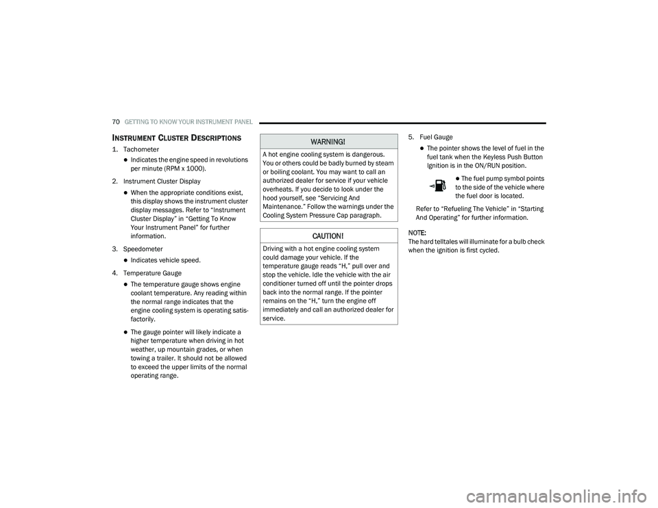
INSTRUMENT CLUSTER DESCRIPTIONS
1. Tachometer
Indicates the engine speed in revolutions
per minute (RPM x 1000).
2. Instrument Cluster Display
When the appropriate conditions exist,
this display shows the instrument cluster
display messages. Refer to “Instrument
Cluster Display” in “Getting To Know
Your Instrument Panel” for further
information.
3. Speedometer
Indicates vehicle speed.
4. Temperature Gauge
The temperature gauge shows engine
coolant temperature. Any reading within
the normal range indicates that the
engine cooling system is operating satis -
factorily.
The gauge pointer will likely indicate a
higher temperature when driving in hot
weather, up mountain grades, or when
towing a trailer. It should not be allowed
to exceed the upper limits of the normal
operating range. 5. Fuel Gauge
The pointer shows the level of fuel in the
fuel tank when the Keyless Push Button
Ignition is in the ON/RUN position.
The fuel pump symbol points
to the side of the vehicle where
the fuel door is located.
Refer to “Refueling The Vehicle” in “Starting
And Operating” for further information.
NOTE:
The hard telltales will illuminate for a bulb check
when the ignition is first cycled.
WARNING!
A hot engine cooling system is dangerous.
You or others could be badly burned by steam
or boiling coolant. You may want to call an
authorized dealer for service if your vehicle
overheats. If you decide to look under the
hood yourself, see “Servicing And
Maintenance.” Follow the warnings under the
Cooling System Pressure Cap paragraph.
CAUTION!
Driving with a hot engine cooling system
could damage your vehicle. If the
temperature gauge reads “H,” pull over and
stop the vehicle. Idle the vehicle with the air
conditioner turned off until the pointer drops
back into the normal range. If the pointer
remains on the “H,” turn the engine off
immediately and call an authorized dealer for
service.
20_LA_OM_EN_USC_t.book Page 70
Page 75 of 396
GETTING TO KNOW YOUR INSTRUMENT PANEL73
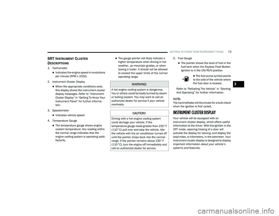
SRT INSTRUMENT CLUSTER
D
ESCRIPTIONS
1. Tachometer
Indicates the engine speed in revolutions
per minute (RPM x 1000).
2. Instrument Cluster Display
When the appropriate conditions exist,
this display shows the instrument cluster
display messages. Refer to “Instrument
Cluster Display” in “Getting To Know Your
Instrument Panel” for further informa -
tion.
3. Speedometer
Indicates vehicle speed.
4. Temperature Gauge
The temperature gauge shows engine
coolant temperature. Any reading within
the normal range indicates that the
engine cooling system is operating satis -
factorily.
The gauge pointer will likely indicate a
higher temperature when driving in hot
weather, up mountain grades, or when
towing a trailer. It should not be allowed
to exceed the upper limits of the normal
operating range. 5. Fuel Gauge
The pointer shows the level of fuel in the
fuel tank when the Keyless Push Button
Ignition is in the ON/RUN position.
The fuel pump symbol points
to the side of the vehicle where
the fuel door is located.
Refer to “Refueling The Vehicle” in “Starting
And Operating” for further information.
NOTE:
The hard telltales will illuminate for a bulb check
when the ignition is first cycled.
INSTRUMENT CLUSTER DISPLAY
Your vehicle will be equipped with an
instrument cluster display, which offers useful
information to the driver. With the ignition in the
OFF mode, opening/closing of a door will
activate the display for viewing, and display the
total miles, or kilometers, in the odometer. Your
instrument cluster display is designed to display
important information about your vehicle’s
systems and features.
WARNING!
A hot engine cooling system is dangerous.
You or others could be badly burned by steam
or boiling coolant. You may want to call an
authorized dealer for service if your vehicle
overheats.
CAUTION!
Driving with a hot engine cooling system
could damage your vehicle. If the
temperature gauge reads greater than 230°F
(110°C) pull over and stop the vehicle. Idle
the vehicle with the air conditioner turned off
until the pointer drops back into the normal
range. If the pointer remains above 230°F
(110°C), turn the engine off immediately and
call an authorized dealer for service.
3
20_LA_OM_EN_USC_t.book Page 73
Page 82 of 396
80GETTING TO KNOW YOUR INSTRUMENT PANEL
2. Upper Right
Compass
Outside Temp (default)
Time
Range
Average (MPG, L/100 km, or km/L)
Current (MPG, L/100 km, or km/L)
Trip A
Trip B
None
3. Center
Menu Title (default)
Digital Speed
None
Compass
Outside Temp.
Time
Range
Average (MPG, L/100 km, or km/L)
Current (MPG, L/100 km, or km/L)
Trip A
Trip B
Audio
4. Current Gear
On
Off (default)
5. Odometer
Show (default)
Hide
6. Gear Display
Full (default)
Single
7. Restore Defaults
Ok
Cancel
Diagnostics — If Equipped
This feature allows the driver to view engine and
emission vehicle faults.
Push OK to have the most recent fault code
sent.
There is a delay when the next diagnostic
code is requested during which the following
message is displayed:
“Checking System for Diagnostic Codes.”
Driver must push the OK button again to see
the next Pcode otherwise current message
remains displayed.
Driver exits when they cycle to another
submenu (up or down).
Faults are displayed from newest to the
oldest.
If the menu is exited before the end of codes
is reached - when the driver re-enters the list
will be restarted from the beginning.
When no codes are present or the last code
is reached = (P0000) and this message is
displayed:
“No or End of Diagnostic Codes.”
20_LA_OM_EN_USC_t.book Page 80
Page 84 of 396
82GETTING TO KNOW YOUR INSTRUMENT PANEL
Turning on all possible vehicle electrical
loads (e.g. HVAC to max settings, exterior
and interior lights, overloaded power outlets
+12 Volts, 115 Volts AC, USB ports) during
certain driving conditions (city driving,
towing, frequent stopping).
Installing options like additional lights,
upfitter electrical accessories, audio
systems, alarms and similar devices.
Unusual driving cycles (short trips separated
by long parking periods).
The vehicle was parked for an extended
period of time (weeks, months).
The battery was recently replaced and was
not charged completely.
The battery was discharged by an electrical
load left on when the vehicle was parked.
The battery was used for an extended period
with the engine not running to supply radio,
lights, chargers, +12 Volts portable appli-
ances like vacuum cleaners, game consoles
and similar devices. What to do when an electrical load reduction
action message is present (“Battery Saver On”
or “Battery Saver Mode”)
During a trip:
Reduce power to unnecessary loads if
possible:
Turn off redundant lights (interior or exte
-
rior)
Check what may be plugged in to power
outlets +12 Volts, 115 Volts AC, USB
ports
Check HVAC settings (blower,
temperature)
Check the audio settings (volume)
After a trip:
Check if any aftermarket equipment was
installed (additional lights, upfitter electrical
accessories, audio systems, alarms) and
review specifications if any (load and Ignition
Off Draw currents).
Evaluate the latest driving cycles (distance,
driving time and parking time).
The vehicle should have service performed if
the message is still present during consecu -
tive trips and the evaluation of the vehicle
and driving pattern did not help to identify the
cause.
WARNING LIGHTS AND MESSAGES
The warning/indicator lights will illuminate in
the instrument panel together with a dedicated
message and/or acoustic signal when
applicable. These indications are indicative and
precautionary and as such must not be
considered as exhaustive and/or alternative to
the information contained in the Owner’s
Manual, which you are advised to read carefully
in all cases. Always refer to the information in
this chapter in the event of a failure indication.
All active telltales will display first if applicable.
The system check menu may appear different
based upon equipment options and current
vehicle status. Some telltales are optional and
may not appear.
20_LA_OM_EN_USC_t.book Page 82
Page 86 of 396
84GETTING TO KNOW YOUR INSTRUMENT PANEL
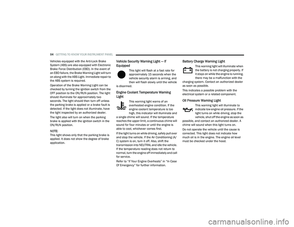
Vehicles equipped with the Anti-Lock Brake
System (ABS) are also equipped with Electronic
Brake Force Distribution (EBD). In the event of
an EBD failure, the Brake Warning Light will turn
on along with the ABS Light. Immediate repair to
the ABS system is required.
Operation of the Brake Warning Light can be
checked by turning the ignition switch from the
OFF position to the ON/RUN position. The light
should illuminate for approximately two
seconds. The light should then turn off unless
the parking brake is applied or a brake fault is
detected. If the light does not illuminate, have
the light inspected by an authorized dealer.
The light also will turn on when the parking
brake is applied with the ignition switch in the
ON/RUN position.
NOTE:
This light shows only that the parking brake is
applied. It does not show the degree of brake
application.Vehicle Security Warning Light — If
Equipped
This light will flash at a fast rate for
approximately 15 seconds when the
vehicle security alarm is arming, and
then will flash slowly until the vehicle
is disarmed.
Engine Coolant Temperature Warning
Light
This warning light warns of an
overheated engine condition. If the
engine coolant temperature is too
high, this indicator will illuminate and
a single chime will sound. If the temperature
reaches the upper limit, a continuous chime will
sound for four minutes or until the engine is
able to cool, whichever comes first.
If the light turns on while driving, safely pull over
and stop the vehicle. If the Air Conditioning (A/
C) system is on, turn it off. Also, shift the
transmission into NEUTRAL and idle the vehicle.
If the temperature reading does not return to
normal, turn the engine off immediately and call
for service.
Refer to “If Your Engine Overheats” in “In Case
Of Emergency” for further information.
Battery Charge Warning Light
This warning light will illuminate when
the battery is not charging properly. If
it stays on while the engine is running,
there may be a malfunction with the
charging system. Contact an authorized dealer
as soon as possible.
This indicates a possible problem with the
electrical system or a related component.
Oil Pressure Warning Light
This warning light will illuminate to
indicate low engine oil pressure. If the
light turns on while driving, stop the
vehicle, shut off the engine as soon as
possible, and contact an authorized dealer. A
chime will sound when this light turns on.
Do not operate the vehicle until the cause is
corrected. This light does not indicate how
much oil is in the engine. The engine oil level
must be checked under the hood.
20_LA_OM_EN_USC_t.book Page 84
Page 87 of 396
GETTING TO KNOW YOUR INSTRUMENT PANEL85
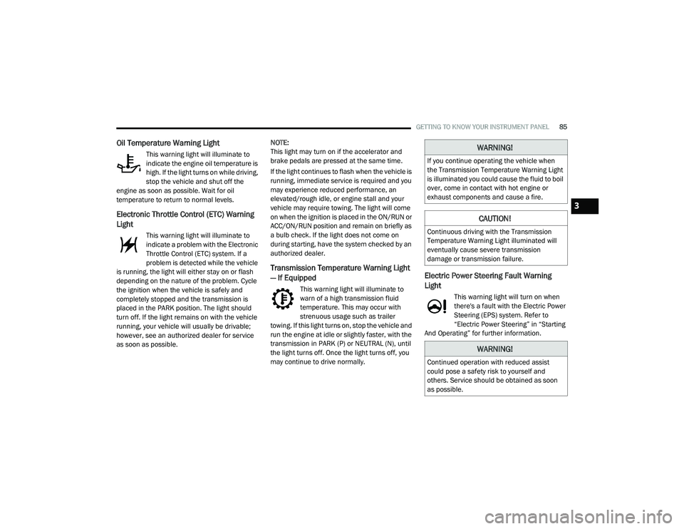
Oil Temperature Warning Light
This warning light will illuminate to
indicate the engine oil temperature is
high. If the light turns on while driving,
stop the vehicle and shut off the
engine as soon as possible. Wait for oil
temperature to return to normal levels.
Electronic Throttle Control (ETC) Warning
Light
This warning light will illuminate to
indicate a problem with the Electronic
Throttle Control (ETC) system. If a
problem is detected while the vehicle
is running, the light will either stay on or flash
depending on the nature of the problem. Cycle
the ignition when the vehicle is safely and
completely stopped and the transmission is
placed in the PARK position. The light should
turn off. If the light remains on with the vehicle
running, your vehicle will usually be drivable;
however, see an authorized dealer for service
as soon as possible. NOTE:
This light may turn on if the accelerator and
brake pedals are pressed at the same time.
If the light continues to flash when the vehicle is
running, immediate service is required and you
may experience reduced performance, an
elevated/rough idle, or engine stall and your
vehicle may require towing. The light will come
on when the ignition is placed in the ON/RUN or
ACC/ON/RUN position and remain on briefly as
a bulb check. If the light does not come on
during starting, have the system checked by an
authorized dealer.
Transmission Temperature Warning Light
— If Equipped
This warning light will illuminate to
warn of a high transmission fluid
temperature. This may occur with
strenuous usage such as trailer
towing. If this light turns on, stop the vehicle and
run the engine at idle or slightly faster, with the
transmission in PARK (P) or NEUTRAL (N), until
the light turns off. Once the light turns off, you
may continue to drive normally.
Electric Power Steering Fault Warning
Light
This warning light will turn on when
there's a fault with the Electric Power
Steering (EPS) system. Refer to
“Electric Power Steering” in “Starting
And Operating” for further information.
WARNING!
If you continue operating the vehicle when
the Transmission Temperature Warning Light
is illuminated you could cause the fluid to boil
over, come in contact with hot engine or
exhaust components and cause a fire.
CAUTION!
Continuous driving with the Transmission
Temperature Warning Light illuminated will
eventually cause severe transmission
damage or transmission failure.
WARNING!
Continued operation with reduced assist
could pose a safety risk to yourself and
others. Service should be obtained as soon
as possible.
3
20_LA_OM_EN_USC_t.book Page 85