spare tire DODGE CHALLENGER 2023 Owners Manual
[x] Cancel search | Manufacturer: DODGE, Model Year: 2023, Model line: CHALLENGER, Model: DODGE CHALLENGER 2023Pages: 300, PDF Size: 12.82 MB
Page 7 of 300
5
IN CASE OF EMERGENCY
HAZARD WARNING FLASHERS ..................................... 199
ASSIST AND SOS MIRROR — IF EQUIPPED .................. 199
JACKING AND TIRE CHANGING ...................................... 202 Preparations For Jacking .......................................... 202
Jack Location/Spare Tire Stowage ......................... 202Jacking And Changing A Tire ................................... 203
TIRE SERVICE KIT — IF EQUIPPED ................................. 206 Alternate Tire Service Kit — If Equipped .................. 211
JUMP STARTING .............................................................. 216 Preparations For Jump Start .................................... 216
Jump Starting Procedure .......................................... 217
IF YOUR ENGINE OVERHEATS ........................................ 218
MANUAL PARK RELEASE–8–SPEED
TRANSMISSION ............................................................... 218
FREEING A STUCK VEHICLE............................................ 220
TOWING A DISABLED VEHICLE ..................................... 221 All Wheel Drive (AWD) Models — If Equipped.......... 222
Rear-Wheel Drive (RWD) Models ............................. 222
ENHANCED ACCIDENT RESPONSE
SYSTEM (EARS) ............................................................... 222
EVENT DATA RECORDER (EDR) ..................................... 222
SERVICING AND MAINTENANCE
SCHEDULED SERVICING ................................................ 223 3.6L And 5.7L Engines ............................................ 223
ENGINE COMPARTMENT ................................................ 228 3.6L Engine .............................................................. 228
5.7L Engine .............................................................. 229
Checking Oil Level .................................................... 230
Adding Washer Fluid................................................. 230Maintenance-Free Battery ....................................... 231
Pressure Washing ..................................................... 231
VEHICLE MAINTENANCE ................................................. 231 Engine Oil ................................................................. 231Engine Oil Filter ......................................................... 233Engine Air Cleaner Filter ........................................... 233Air Conditioner Maintenance ................................... 234Accessory Drive Belt Inspection............................... 235
Body Lubrication ....................................................... 235
Windshield Wiper Blades ......................................... 236
Exhaust System ........................................................ 237Cooling System ......................................................... 237Brake System ........................................................... 240
Clutch Hydraulic System —
Manual Transmission (If Equipped) ........................ 240
Manual Transmission — If Equipped ....................... 240
Automatic Transmission — If Equipped ................... 241
All-Wheel Drive (AWD) — If Equipped ...................... 241Rear Axle ................................................................... 241
Fuses ......................................................................... 242
Bulb Replacement .................................................... 250 TIRES ..................................................................................253
Tire Safety Information ............................................. 253
Tires — General Information ..................................... 261
Tire Types ................................................................... 264Spare Tires — If Equipped ......................................... 264
Wheel And Wheel Trim Care ..................................... 266
Snow Traction Devices ............................................. 267
Tire Rotation Recommendations ............................. 268
DEPARTMENT OF TRANSPORTATION UNIFORM
TIRE QUALITY GRADES ................................................... 268 Treadwear .................................................................. 268
Traction Grades ......................................................... 269
Temperature Grades ................................................. 269
VEHICLE STORAGE ...........................................................269
BODYWORK ......................................................................270 Protection From Atmospheric Agents ...................... 270
Body And Underbody Maintenance.......................... 270
Preserving The Bodywork ......................................... 270
INTERIORS ........................................................................ 271 Seats And Fabric Parts.............................................. 271Plastic And Coated Parts .......................................... 271
Leather Surfaces ....................................................... 272
Glass Surfaces .......................................................... 272
23_LA_OM_EN_USC_t.book Page 5
Page 69 of 300
GETTING TO KNOW YOUR INSTRUMENT PANEL67
Loose Fuel Filler Cap Warning Light —
If Equipped
This warning light will illuminate when the fuel
filler cap is loose. Properly close the filler cap to
disengage the light. If the light does not turn
off, please see an authorized dealer.
Engine Check/Malfunction Indicator
Warning Light (MIL)
The Engine Check/Malfunction Indicator Light
(MIL) is a part of an Onboard Diagnostic System
called OBD II that monitors engine and
automatic transmission control systems.
This warning light will illuminate when the ignition is in the
ON/RUN position before engine start. If the bulb does not
come on when turning the ignition switch from OFF to
ON/RUN, have the condition checked promptly.
Certain conditions, such as a loose or missing gas cap,
poor quality fuel, etc., may illuminate the light after engine
start. The vehicle should be serviced if the light stays on
through several typical driving styles. In most situations,
the vehicle will drive normally and will not require towing.
When the engine is running, the MIL may flash to alert
serious conditions that could lead to immediate loss of
power or severe catalytic converter damage. The vehicle
should be serviced by an authorized dealer as soon as
possible if this occurs.
Service AWD Warning Light — If Equipped
This telltale will turn on to indicate the All Wheel
Drive (AWD) system is not functioning properly
and that service is required. Contact an
authorized dealer.
Service Forward Collision Warning (FCW)
Light — If Equipped
This warning light will illuminate to indicate a
fault in the Forward Collision Warning System.
Contact an authorized dealer for service
Úpage 167.
Tire Pressure Monitoring System (TPMS)
Warning Light
The warning light switches on and a message is
displayed to indicate that the tire pressure is
lower than the recommended value and/or
that slow pressure loss is occurring. In these
cases, optimal tire duration and fuel consumption may not
be guaranteed.
Should one or more tires be in the condition mentioned
previously, the display will show the indications
corresponding to each tire.
Each tire, including the spare (if provided), should be
checked monthly when cold and inflated to the inflation
pressure recommended by the vehicle manufacturer on
the vehicle placard or tire inflation pressure label. If your
vehicle has tires of a different size than the size indicated
on the vehicle placard or tire inflation pressure label, you
should determine the proper tire inflation pressure for
those tires.
WARNING!
A malfunctioning catalytic converter can reach higher
temperatures than in normal operating conditions. This
can cause a fire if you drive slowly or park over
flammable substances such as dry plants, wood,
cardboard, etc. This could result in death or serious
injury to the driver, occupants or others.
CAUTION!
Prolonged driving with the Malfunction Indicator Light
(MIL) on could cause damage to the vehicle control
system. It also could affect fuel economy and
driveability. If the MIL is flashing, severe catalytic
converter damage and power loss will soon occur.
Immediate service is required.CAUTION!
Do not continue driving with one or more flat tires as
handling may be compromised. Stop the vehicle,
avoiding sharp braking and steering. If a tire puncture
occurs, repair immediately using the dedicated tire
repair kit and contact an authorized dealer as soon as
possible.
3
23_LA_OM_EN_USC_t.book Page 67
Page 104 of 300

102STARTING AND OPERATING
Perform the maintenance listed in the “Scheduled
Servicing” Úpage 223. When towing a trailer, never
exceed the GAWR or GCWR ratings.
Towing Requirements — Tires
Do not attempt to tow a trailer while using a compact
spare tire.
Do not drive more than 50 mph (80 km/h) when towing
while using a full size spare tire.
Proper tire inflation pressures are essential to the safe
and satisfactory operation of your vehicle. For proper
tire inflation procedures.
Check the trailer tires for proper tire inflation pressures
before trailer usage.
Check for signs of tire wear or visible tire damage
before towing a trailer.
Replacing tires with a higher load carrying capacity will
not increase the vehicle's GVWR and GAWR limits.
For further information
Úpage 253.
Towing Requirements — Trailer Brakes
Do not interconnect the hydraulic brake system or
vacuum system of your vehicle with that of the trailer.
This could cause inadequate braking and possible
personal injury.
An electronically actuated trailer brake controller is
required when towing a trailer with electronically actu -
ated brakes. When towing a trailer equipped with a
hydraulic surge actuated brake system, an electronic
brake controller is not required.
Trailer brakes are recommended for trailers over
1,000 lb (453 kg) and required for trailers in excess of
2,000 lb (907 kg).
Towing Requirements — Trailer Lights And
Wiring
Whenever you pull a trailer, regardless of the trailer size,
stoplights and turn signals on the trailer are required for
motoring safety.
The Trailer Tow Package may include a four- and seven-pin
wiring harness. Use a factory approved trailer harness and
connector.
NOTE:Do not cut or splice wiring into the vehicle’s wiring
harness.
CAUTION!
Do not tow a trailer at all during the first 500 miles
(805 km) the new vehicle is driven. The engine, axle
or other parts could be damaged.
Then, during the first 500 miles (805 km) that a
trailer is towed, do not drive over 50 mph (80 km/h)
and do not make starts at full throttle. This helps the
engine and other parts of the vehicle wear in at the
heavier loads.
WARNING!
Do not connect trailer brakes to your vehicle's
hydraulic brake lines. It can overload your brake
system and cause it to fail. You might not have
brakes when you need them and could have an acci -
dent.
Towing any trailer will increase your stopping
distance. When towing, you should allow for addi -
tional space between your vehicle and the vehicle in
front of you. Failure to do so could result in an
accident.
CAUTION!
If the trailer weighs more than 1,000 lb (453 kg)
loaded, it should have its own brakes and they should
be of adequate capacity. Failure to do this could lead to
accelerated brake lining wear, higher brake pedal
effort, and longer stopping distances.
23_LA_OM_EN_USC_t.book Page 102
Page 173 of 300
SAFETY171
If the ignition switch is cycled, this sequence will repeat,
providing the system fault still exists. If the system fault no
longer exists, the TPMS Warning Light will no longer flash,
and the "Service Tire Pressure System" message will no
longer display, and a pressure value will display in place of
the dashes. A system fault can occur due to any of the
following:
Signal interference due to electronic devices or driving
next to facilities emitting the same radio frequencies
as the TPMS sensors
Accumulation of snow or ice around the wheels or
wheel housings
Using tire chains on the vehicle
Using wheels/tires not equipped with TPMS sensors
Vehicles With Compact Spare
1. The compact spare tire or non-matching full size does not have a Tire Pressure Monitoring System
sensor. Therefore, the TPMS will not monitor the
pressure in the compact or non-matching full size
spare tire.
2. If you install the compact or non-matching full size spare tire in place of a road tire that has a pressure
below the low-pressure warning limit, upon the next
ignition key cycle, the TPMS Warning Light will remain
on and a chime will sound. In addition, the graphic in
the instrument cluster will still display a different
color pressure value and an "Inflate to XX" message. 3. After driving the vehicle for up to 20 minutes above
15 mph (24 km/h), the TPMS Warning Light will flash
on and off for 75 seconds and then remain on solid.
In addition, the instrument cluster will display a
“Service Tire Pressure System” message for five
seconds and then display dashes (- -) in place of the
pressure value.
4. For each subsequent ignition key cycle, a chime will sound, the TPMS Warning Light will flash on and off
for 75 seconds and then remain on solid, and the
instrument cluster will display a “Service Tire
Pressure System” message for five seconds and then
display dashes (- -) in place of the pressure value.
5. Once you repair or replace the original road tire and reinstall it on the vehicle in place of the compact
spare or non-matching full size, the TPMS will update
automatically. In addition, the TPMS Warning Light
will turn off and the graphic in the instrument cluster
will display a new pressure value instead of dashes
(- -), as long as no tire pressure is below the
low-pressure warning limit in any of the four active
road tires. The vehicle may need to be driven for up to
20 minutes above 15 mph (24 km/h) in order for the TPMS to receive this information.TPMS Deactivation — If Equipped
The Tire Pressure Monitoring System (TPMS) can be
deactivated if replacing all four wheel and tire assemblies
(road tires) with wheel and tire assemblies that do not
have TPMS sensors, such as when installing winter wheel
and tire assemblies on your vehicle.
To deactivate the TPMS, first replace all four wheel and
tire assemblies (road tires) with tires not equipped with
Tire Pressure Monitoring System (TPMS) sensors. Then,
drive the vehicle for 20 minutes above 15 mph (24 km/h).
The TPMS will chime, the TPMS Warning Light will flash on
and off for 75 seconds and then remain on. The
instrument cluster will display the “Service Tire Pressure
System” message and then display dashes (--) in place of
the pressure values.
Beginning with the next ignition cycle, the TPMS will no
longer chime or display the “Service Tire Pressure System”
message in the instrument cluster but dashes (--) will
remain in place of the pressure values.
To reactivate the TPMS, replace all four wheel and tire
assemblies (road tires) with tires equipped with TPMS
sensors. Then, drive the vehicle for up to 20 minutes
above 15 mph (24 km/h). The TPMS will chime, the TPMS
Warning Light will flash on and off for 75 seconds and then
turn off. The instrument cluster will display the “Service
Tire Pressure System” message and then display pressure
values in place of the dashes. On the next ignition cycle
the "Service Tire Pressure System" message will no longer
be displayed as long as no system fault exists.
6
23_LA_OM_EN_USC_t.book Page 171
Page 200 of 300

198SAFETY
PERIODIC SAFETY CHECKS YOU SHOULD
M
AKE OUTSIDE THE VEHICLE
Tires
Examine tires for excessive tread wear and uneven wear
patterns. Check for stones, nails, glass, or other objects
lodged in the tread or sidewall. Inspect the tread for cuts
and cracks. Inspect sidewalls for cuts, cracks, and bulges.
Check the lug nuts/bolt torque for tightness. Check the
tires (including spare) for proper cold inflation pressure.
Lights
Have someone observe the operation of brake lights and
exterior lights while you work the controls. Check turn
signal and high beam indicator lights on the instrument
panel.
Door Latches
Check for proper closing, latching, and locking.
Fluid Leaks
Check area under the vehicle after overnight parking for
fuel, coolant, oil, or other fluid leaks. Also, if gasoline
fumes are detected or if fuel or brake fluid leaks are
suspected, the cause should be located and corrected
immediately.
EXHAUST GAS
The best protection against carbon monoxide entry into
the vehicle body is a properly maintained engine exhaust
system. Whenever a change is noticed in the sound of the exhaust
system, when exhaust fumes can be detected inside the
vehicle, or when the underside or rear of the vehicle is
damaged, have an authorized dealer inspect the complete
exhaust system and adjacent body areas for broken,
damaged, deteriorated, or mispositioned parts. Open
seams or loose connections could permit exhaust fumes
to seep into the passenger compartment. In addition,
inspect the exhaust system each time the vehicle is raised
for lubrication or oil change. Replace as required.
CARBON MONOXIDE WARNINGS
WARNING!
Exhaust gases can injure or kill. They contain carbon
monoxide (CO), which is colorless and odorless.
Breathing it can make you unconscious and can
eventually poison you. To avoid breathing (CO), follow
these safety tips:
Do not run the engine in a closed garage or in
confined areas any longer than needed to move your
vehicle in or out of the area.
If you are required to drive with the trunk/liftgate/
rear doors open, make sure that all windows are
closed and the climate control BLOWER switch is set
at high speed. DO NOT use the recirculation mode.
If it is necessary to sit in a parked vehicle with the
engine running, adjust your heating or cooling
controls to force outside air into the vehicle. Set the
blower at high speed.
WARNING!
Carbon monoxide (CO) in exhaust gases is deadly.
Follow the precautions below to prevent carbon
monoxide poisoning:
Do not inhale exhaust gases. They contain carbon
monoxide, a colorless and odorless gas, which can
kill. Never run the engine in a closed area, such as a
garage, and never sit in a parked vehicle with the
engine running for an extended period. If the vehicle
is stopped in an open area with the engine running
for more than a short period, adjust the ventilation
system to force fresh, outside air into the vehicle.
Guard against carbon monoxide with proper mainte -
nance. Have the exhaust system inspected every
time the vehicle is raised. Have any abnormal condi -
tions repaired promptly. Until repaired, drive with all
side windows fully open.
23_LA_OM_EN_USC_t.book Page 198
Page 204 of 300
202IN CASE OF EMERGENCY
(Continued)
Automatic SOS — If Equipped
Automatic SOS is a hands-free safety service that can
immediately connect you with help in the event that your
vehicle’s airbags deploy. Please refer to your provided
radio supplement for complete information.
JACKING AND TIRE CHANGING
Use this QR code to access your digital
experience.PREPARATIONS FOR JACKING
1. Park the vehicle on a firm, level surface as far from
the edge of the roadway as possible. Avoid icy or
slippery areas.
2. Turn on the Hazard Warning Flashers.
3. Apply the parking brake.
4. Place the gear selector into PARK (automatic transmission) or FIRST gear (manual transmission).
5. Turn the ignition OFF. 6. Block both the front and rear of the wheel diagonally
opposite the jacking position. For example, if the
driver’s front wheel is being changed, block the
passenger’s rear wheel.
Wheel Blocked Example
NOTE:Passengers should not remain in the vehicle when the
vehicle is being lifted or raised.
JACK LOCATION/SPARE TIRE STOWAGE
The jack, tools and spare tire are stowed under the load
floor in the trunk. Follow the next steps to access the jack
and spare tire.
NOTE:The spare tire must be removed in order to access the
jack.
1. Open the trunk.
2. Lift the access cover using the pull strap.
WARNING!
Do not attempt to change a tire on the side of the
vehicle close to moving traffic. Pull far enough off the
road to avoid the danger of being hit when operating
the jack or changing the wheel.
Being under a jacked-up vehicle is dangerous. The
vehicle could slip off the jack and fall on you. You
could be crushed. Never put any part of your body
under a vehicle that is on a jack. If you need to get
under a raised vehicle, take it to a service center
where it can be raised on a lift.
Never start or run the engine while the vehicle is on
a jack.
The jack is designed to be used as a tool for changing
tires only. The jack should not be used to lift the
vehicle for service purposes. The vehicle should be
jacked on a firm level surface only. Avoid ice or slip -
pery areas.
WARNING!
Do not attempt to change a tire on the side of the
vehicle close to moving traffic, pull far enough off the
road to avoid being hit when operating the jack or
changing the wheel.
WARNING!
23_LA_OM_EN_USC_t.book Page 202
Page 205 of 300
IN CASE OF EMERGENCY203
(Continued)
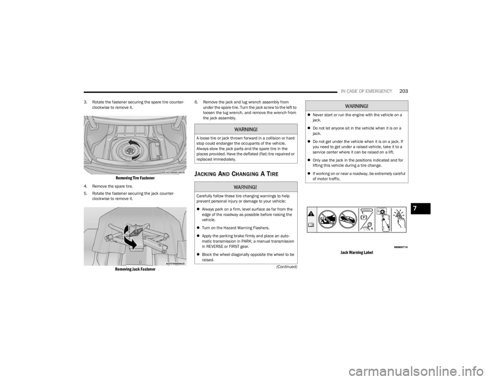
3. Rotate the fastener securing the spare tire counter
-
clockwise to remove it.
Removing Tire Fastener
4. Remove the spare tire.
5. Rotate the fastener securing the jack counter -
clockwise to remove it.
Removing Jack Fastener
6. Remove the jack and lug wrench assembly from under the spare tire. Turn the jack screw to the left to
loosen the lug wrench, and remove the wrench from
the jack assembly.
JACKING AND CHANGING A TIRE
Jack Warning Label
WARNING!
A loose tire or jack thrown forward in a collision or hard
stop could endanger the occupants of the vehicle.
Always stow the jack parts and the spare tire in the
places provided. Have the deflated (flat) tire repaired or
replaced immediately.
WARNING!
Carefully follow these tire changing warnings to help
prevent personal injury or damage to your vehicle:
Always park on a firm, level surface as far from the
edge of the roadway as possible before raising the
vehicle.
Turn on the Hazard Warning Flashers.
Apply the parking brake firmly and place an auto -
matic transmission in PARK; a manual transmission
in REVERSE or FIRST gear.
Block the wheel diagonally opposite the wheel to be
raised.
Never start or run the engine with the vehicle on a
jack.
Do not let anyone sit in the vehicle when it is on a
jack.
Do not get under the vehicle when it is on a jack. If
you need to get under a raised vehicle, take it to a
service center where it can be raised on a lift.
Only use the jack in the positions indicated and for
lifting this vehicle during a tire change.
If working on or near a roadway, be extremely careful
of motor traffic.
WARNING!
7
23_LA_OM_EN_USC_t.book Page 203
Page 206 of 300
204IN CASE OF EMERGENCY
1. Remove the spare tire, jack, and lug wrench.
2. If equipped with aluminum wheels where the center
cap covers the lug nuts, use the lug wrench to pry the
center cap off carefully before raising the vehicle.
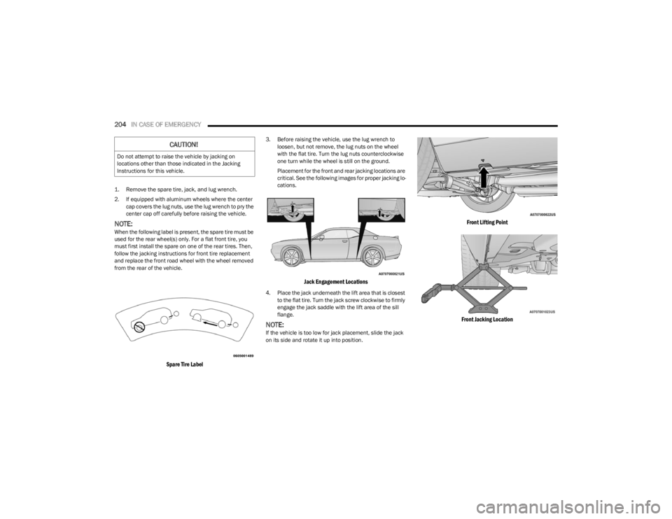
NOTE:When the following label is present, the spare tire must be
used for the rear wheel(s) only. For a flat front tire, you
must first install the spare on one of the rear tires. Then,
follow the jacking instructions for front tire replacement
and replace the front road wheel with the wheel removed
from the rear of the vehicle.
Spare Tire Label
3. Before raising the vehicle, use the lug wrench to loosen, but not remove, the lug nuts on the wheel
with the flat tire. Turn the lug nuts counterclockwise
one turn while the wheel is still on the ground.
Placement for the front and rear jacking locations are
critical. See the following images for proper jacking lo -
cations.
Jack Engagement Locations
4. Place the jack underneath the lift area that is closest to the flat tire. Turn the jack screw clockwise to firmly
engage the jack saddle with the lift area of the sill
flange.
NOTE:If the vehicle is too low for jack placement, slide the jack
on its side and rotate it up into position.
Front Lifting Point
Front Jacking Location
CAUTION!
Do not attempt to raise the vehicle by jacking on
locations other than those indicated in the Jacking
Instructions for this vehicle.
23_LA_OM_EN_USC_t.book Page 204
Page 207 of 300
IN CASE OF EMERGENCY205
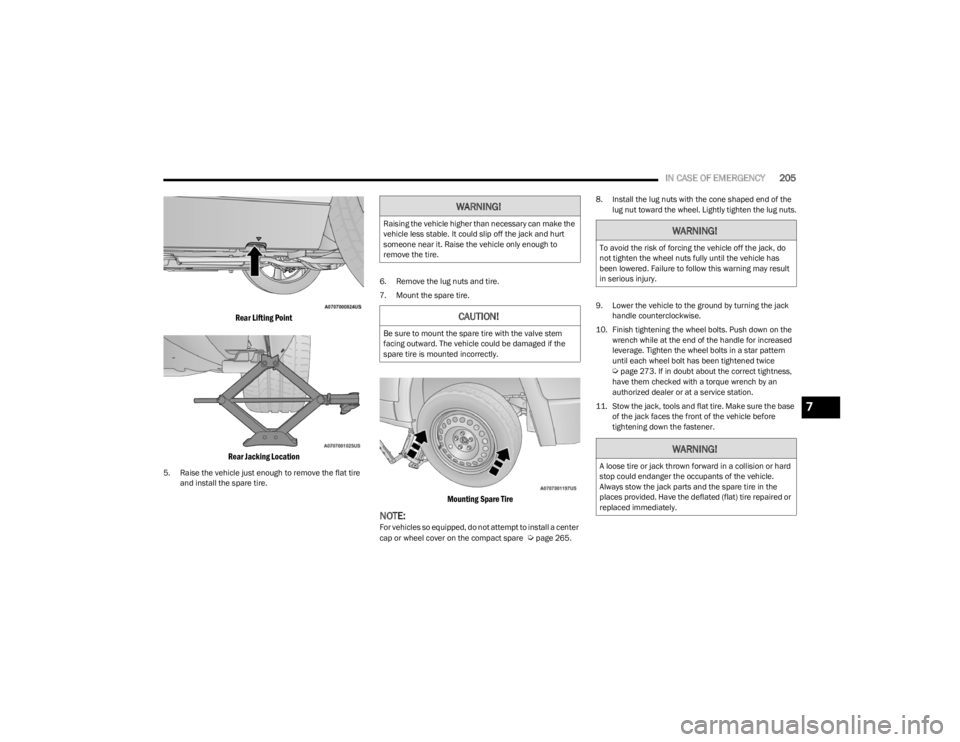
Rear Lifting Point
Rear Jacking Location
5. Raise the vehicle just enough to remove the flat tire and install the spare tire. 6. Remove the lug nuts and tire.
7. Mount the spare tire.
Mounting Spare Tire
NOTE:For vehicles so equipped, do not attempt to install a center
cap or wheel cover on the compact spare Úpage 265.8. Install the lug nuts with the cone shaped end of the
lug nut toward the wheel. Lightly tighten the lug nuts.
9. Lower the vehicle to the ground by turning the jack handle counterclockwise.
10. Finish tightening the wheel bolts. Push down on the wrench while at the end of the handle for increased
leverage. Tighten the wheel bolts in a star pattern
until each wheel bolt has been tightened twice
Úpage 273. If in doubt about the correct tightness,
have them checked with a torque wrench by an
authorized dealer or at a service station.
11. Stow the jack, tools and flat tire. Make sure the base of the jack faces the front of the vehicle before
tightening down the fastener.
WARNING!
Raising the vehicle higher than necessary can make the
vehicle less stable. It could slip off the jack and hurt
someone near it. Raise the vehicle only enough to
remove the tire.
CAUTION!
Be sure to mount the spare tire with the valve stem
facing outward. The vehicle could be damaged if the
spare tire is mounted incorrectly.
WARNING!
To avoid the risk of forcing the vehicle off the jack, do
not tighten the wheel nuts fully until the vehicle has
been lowered. Failure to follow this warning may result
in serious injury.
WARNING!
A loose tire or jack thrown forward in a collision or hard
stop could endanger the occupants of the vehicle.
Always stow the jack parts and the spare tire in the
places provided. Have the deflated (flat) tire repaired or
replaced immediately.
7
23_LA_OM_EN_USC_t.book Page 205
Page 248 of 300
246SERVICING AND MAINTENANCE
Rear Fuses
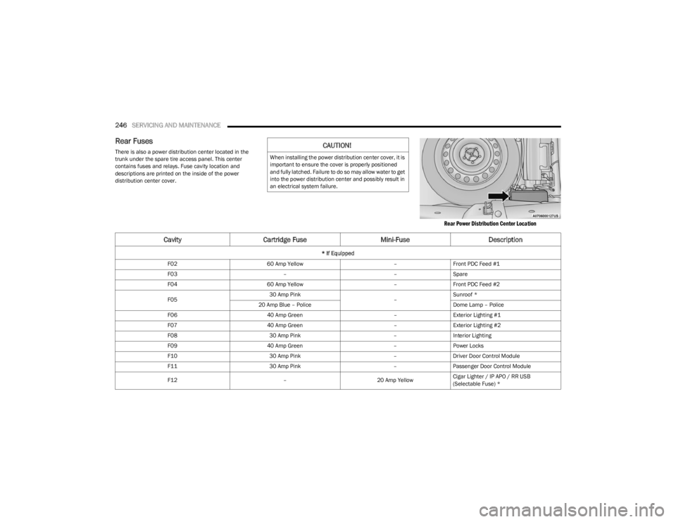
There is also a power distribution center located in the
trunk under the spare tire access panel. This center
contains fuses and relays. Fuse cavity location and
descriptions are printed on the inside of the power
distribution center cover.
Rear Power Distribution Center Location
CAUTION!
When installing the power distribution center cover, it is
important to ensure the cover is properly positioned
and fully latched. Failure to do so may allow water to get
into the power distribution center and possibly result in
an electrical system failure.
CavityCartridge Fuse Mini-FuseDescription
* If Equipped
F02 60 Amp Yellow –Front PDC Feed #1
F03 ––Spare
F04 60 Amp Yellow –Front PDC Feed #2
F05 30 Amp Pink
–Sunroof *
20 Amp Blue – Police Dome Lamp – Police
F06 40 Amp Green –Exterior Lighting #1
F07 40 Amp Green –Exterior Lighting #2
F08 30 Amp Pink –Interior Lighting
F09 40 Amp Green –Power Locks
F10 30 Amp Pink –Driver Door Control Module
F11 30 Amp Pink –Passenger Door Control Module
F12 –20 Amp YellowCigar Lighter / IP APO / RR USB
(Selectable Fuse) *
23_LA_OM_EN_USC_t.book Page 246