DODGE CHALLENGER SRT 2015 3.G Owners Manual
Manufacturer: DODGE, Model Year: 2015, Model line: CHALLENGER SRT, Model: DODGE CHALLENGER SRT 2015 3.GPages: 575, PDF Size: 4.37 MB
Page 301 of 575
Launch Control screen. Within Race Options, you can
activate, deactivate, and adjust the RPM values for the
Launch Control and Shift Light features.
Launch Control
WARNING!
Launch Mode is intended for off-highway or off-road
use only and should not be used on any public
roadways. It is recommended that this feature be
used in a controlled environment, and within the
limits of the law. The capabilities of the vehicle as
measured by the performance pages must never be
exploited in a reckless or dangerous manner, which
can jeopardize the user ’s safety or the safety of
others. Only a safe, attentive, and skillful driver can
prevent accidents.Launch Control can be accessed by pushing the Launch
Control button on the instrument panel switch bank or
pressing the SRT button on the instrument panel switch
bank then selecting the“Race Options” button on the
touchscreen. Press the “Activate Launch Control” button
on the touchscreen to activate the feature. Press the
Activate Launch Control
4
UNDERSTANDING YOUR INSTRUMENT PANEL 299
Page 302 of 575
“Launch RPM Set-Up” to set the holding RPM. Launch
Mode can be turned on or off by either pushing the
Launch Control button on the instrument panel switch
bank (if activated), or by pressing the “Cancel Launch
Mode” button on the touchscreen.
NOTE:Launch RPM Set-Up cannot be accessed unless
Launch Mode is deactivated.
To adjust the Launch RPM, drag the slider bar or press
the arrows on the touchscreen to adjust the holding RPM.
The launch RPM limits will vary between the automatic
transmissions (1500–3500 RPM) and manual transmis-
sions (2000–4500 RPM).
Launch RPM Set-Up — Manual Transmission
300 UNDERSTANDING YOUR INSTRUMENT PANEL
Page 303 of 575
For further information refer to “Drive Modes” in “Start-
ing and Operating”.
Shift Light
To actuate the Shift Light feature, press the “Shift Light”
button on the touchscreen, then press the “Shift LightOn” button on the touchscreen. Activation is shown on
the Driver Information Display (DID). Pressing the “Shift
Light RPM Set-Up” button on the touchscreen will take
you to the Shift Light RPM Set-Up screen.
The Shift Light RPM Set-Up allows you to set the shift
light to actuate for gears 1, 2, 3, 4, and 5-8 (automatic
Shift LightShift Light RPM Set-Up
4
UNDERSTANDING YOUR INSTRUMENT PANEL 301
Page 304 of 575
transmission) 1, 2, 3, 4, and 5–6 (manual transmission).
Pressing and releasing the up/down arrow buttons on
the touchscreen above and below each listed gear, the
RPM values will change in increments of 250 RPM.
Pressing and holding the arrows will change the RPM
values in increments of 500 RPM, ranging from 2000–
6000 RPM. The Shift Light setup screen may only be
accessed if the feature is enabled, press the “Reset to
factory default” button on the touchscreen to change
back to factory settings, or press the “Shift Light Off”
button on the touchscreen to turn the system off com-
pletely.Valet Mode
To enter Valet Mode press the “Valet” button on the
touchscreen and a popup screen will ask you if you
would like to enter Valet Mode, after selecting “Yes” you
will be asked to enter a 4 digit PIN code. The PIN code is
Valet Mode Activation
302 UNDERSTANDING YOUR INSTRUMENT PANEL
Page 305 of 575
not set, so you are free to select any 4 digit numeric
combination that will be easy to remember.
While in Valet Mode the following vehicle configurations
are set and locked to prevent unauthorized modification:
•Engine limited to the lowest power output state.
• Transmission locks out access to first gear and up-
shifts earlier than normal.
• Traction, Steering, and Suspension are set to their
STREET settings.
• Steering wheel paddle shifters are disabled.
• The Drive Mode interface is not available. Pressing the
SRT button on the touchscreen will display the unlock
keypad.
• The ESC Off button is disabled.
• The Launch Control button is disabled. To exit Valet Mode you must enter the same 4 digit PIN
that was used to enter the mode. The unlock keypad can
be accessed by either pushing the SRT button on the
faceplate, or pressing the “Valet Mode Active – Press
Here to Exit” button on the touchscreen.
Valet Mode Deactivation
4
UNDERSTANDING YOUR INSTRUMENT PANEL 303
Page 306 of 575
The Valet Mode Deactivation key pad will then prompt
you for your 4 digit PIN code, enter your PIN code and
press the “OK” button on the touchscreen. Your vehicle
will return to the default state after a key cycle.
NOTE:If your 4 digit PIN is lost or forgotten, the vehicle
will exit Valet Mode after a battery disconnect for ap-
proximately one minute. Reconnect the battery and cycle
the ignition to the RUN position, the vehicle will be in
Default Mode.
Valet Mode Deactivation PIN
304 UNDERSTANDING YOUR INSTRUMENT PANEL
Page 307 of 575
ECO Mode — If Equipped With Automatic
Transmission
Press the “Eco” button on the touchscreen on the SRT
Drive Modes main menu. Eco mode modifies the vehi-
cle’s engine and transmission settings to provide im-proved fuel economy at a trade-off with acceleration
performance. Increased engine exhaust noise and/or
vibration may be noticed while Eco is active. This is
normal and a result of the increased amount of operating
conditions where the vehicle is allowed to operate in four
cylinder shutoff mode (6.4L Only).
The Paddle Shifters will be disabled while in Eco mode.
•
Changing the Drive Mode will deactivate Eco.
• Eco will be disabled when another Drive Mode is
selected or “Eco” button is pressed.
Uconnect® RADIOS — IF EQUIPPED
For detailed information about your Uconnect® radio,
refer to your Uconnect® Supplement Manual.
iPod®/USB/MP3 CONTROL — IF EQUIPPED
This feature allows an iPod® or external USB device to be
plugged into the USB port.
Eco Mode
4
UNDERSTANDING YOUR INSTRUMENT PANEL 305
Page 308 of 575
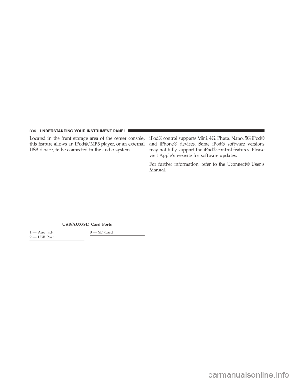
Located in the front storage area of the center console,
this feature allows an iPod®/MP3 player, or an external
USB device, to be connected to the audio system.iPod® control supports Mini, 4G, Photo, Nano, 5G iPod®
and iPhone® devices. Some iPod® software versions
may not fully support the iPod® control features. Please
visit Apple’s website for software updates.
For further information, refer to the Uconnect® User ’s
Manual.
USB/AUX/SD Card Ports
1 — Aux Jack
2 — USB Port3 — SD Card
306 UNDERSTANDING YOUR INSTRUMENT PANEL
Page 309 of 575
STEERING WHEEL AUDIO CONTROLS — IF
EQUIPPED
The remote sound system controls are located on the rear
surface of the steering wheel. Reach behind the wheel to
access the switches.The right-hand control is a rocker-type switch with a
push-button in the center and controls the volume and
mode of the sound system. Pushing the top of the rocker
switch will increase the volume, and pushing the bottom
of the rocker switch will decrease the volume.
Pushing the center button will make the radio switch
between the various modes available (AM/FM/AUX
etc.).
The left-hand control is a rocker-type switch with a
push-button in the center. The function of the left-hand
control is different depending on which mode you are in.
The following describes the left-hand control operation in
each mode.
Radio Operation
Pushing the top of the switch will “Seek” up for the next
listenable station and pushing the bottom of the switch
will “Seek” down for the next listenable station.
Remote Sound Controls (Back View Of Steering Wheel)
4
UNDERSTANDING YOUR INSTRUMENT PANEL 307
Page 310 of 575
The button located in the center of the left-hand control
will tune to the next preset station that you have pro-
grammed in the radio preset button.
Media Mode
Pushing the top of the switch once will go to the next
track on the selected media (AUX, Bluetooth®, SD Card).
Pushing the bottom of the switch once will go to the
beginning of the current track, or to the beginning of the
previous track if it is within eight seconds after the
current track begins to play.
If you push the switch up or down twice, it plays the
second track; three times, it will play the third, etc.
RADIO OPERATION AND MOBILE PHONES
Under certain conditions, the mobile phone being on in
your vehicle can cause erratic or noisy performance from
your radio. This condition may be lessened or eliminated
by relocating the mobile phone antenna. This condition isnot harmful to the radio. If your radio performance does
not satisfactorily “clear” by the repositioning of the
antenna, it is recommended that the radio volume be
turned down or off during mobile phone operation when
not using Uconnect® (if equipped).
Regulatory And Safety Information
USA/CANADA
Exposure to Radio Frequency Radiation
The radiated output power of the internal wireless radio
is far below the FCC radio frequency exposure limits.
Nevertheless, the wireless radio will be used in such a
manner that the radio is 20 cm or further from the human
body.
The internal wireless radio operates within guidelines
found in radio frequency safety standards and recom-
mendations, which reflect the consensus of the scientific
community.
308 UNDERSTANDING YOUR INSTRUMENT PANEL