parking brake DODGE CHARGER 2021 Owner's Manual
[x] Cancel search | Manufacturer: DODGE, Model Year: 2021, Model line: CHARGER, Model: DODGE CHARGER 2021Pages: 320, PDF Size: 20.61 MB
Page 173 of 320
MULTIMEDIA171
With a USB jump drive installed, press the USB
button to save to the jump drive.
Press the Uconnect button to save the current
timer data to the Owner’s web page.
NOTE:The Uconnect option will be grayed out or missing
if the vehicle does not have a valid Uconnect
account associated with it.
Press the Cancel button to return to the Timers
page.
The tabs on the Timers page contain the timers
listed below:
Reaction Time
Measures the driver's reaction time for
launching the vehicle against a simulated drag
strip timing light (behavior modeled after 500
Sportsman Tree) displayed in the instrument
cluster display.
NOTE:Drag timers (RT, 60 ft [20 m], 330 ft [100 m],
1/8 mile [200 m], 1000 ft [300 m], and 1/4 mile
[400 m]).
NOTE:Accel & Braking timers (0-60 mph [0-100 km/h],
0-100 mph [0-160 km/h], Brake from mph
[km/h], and Brake Distance ft [meters]).
0-60 mph (0-100 km/h)
Displays the time it takes for the vehicle to go
from 0 to 60 mph (0 to 100 km/h).
0-100 mph (0-160 km/h)
Displays the time it takes for the vehicle to go
from 0 to 100 mph (0 to 160 km/h).
60 ft (20 m) ET
Displays the time it takes the vehicle to go
60 feet (20 m).
330 ft (100 m) ET
Displays the time it takes the vehicle to go
330 feet (100 m).
⅛ Mile (200 m) ET
Displays the time it takes for the vehicle to go
⅛ mile (200 m).
⅛ Mile (200 m) mph
Displays the vehicle speed at the time ⅛ mile
(200 m) was reached.
1000 ft (300 m) ET
Displays the time it takes the vehicle to go
1000 ft (300 m).
¼ Mile (400 m) ET
Displays the time it takes for the vehicle to go
¼ mile (400 m).
¼ Mile (400 m) mph
Displays the speed the vehicle was at when
¼ mile (400 m) was reached.
Brake Distance ft (meters)
Displays the distance it takes the vehicle to
make a complete stop.
NOTE:The distance measurement will be aborted if the
brake pedal is released or the parking brake is
engaged, before the vehicle comes to a complete
stop.
Brake from mph (km/h)
Displays the speed the vehicle is traveling when
the brake pedal is pressed.
NOTE:Brake Distance and Speed timers only display
"ready" when vehicle is traveling at greater than
30 mph (48 km/h).
5
21_LD_OM_EN_USC_t.book Page 171
Page 186 of 320
184SAFETY
NOTE:
The ESC Activation/Malfunction Indicator
Light and the ESC OFF Indicator Light come on
momentarily each time the ignition is placed in
the ON mode.
Each time the ignition is placed in the ON mode,
the ESC system will be on even if it was turned
off previously.
The ESC system will make buzzing or clicking
sounds when it is active. This is normal; the
sounds will stop when ESC becomes inactive
following the maneuver that caused the ESC
activation.
Hill Start Assist (HSA)
HSA is designed to mitigate roll back from a
complete stop while on an incline. If the driver
releases the brake while stopped on an incline,
HSA will continue to hold the brake pressure for a
short period. If the driver does not apply the
throttle before this time expires, the system will
release brake pressure and the vehicle will roll
down the hill as normal.
The following conditions must be met in order for
HSA to activate:
The feature must be enabled.
The vehicle must be stopped.
The parking brake must be off.
The driver door must be closed.
The vehicle must be on a sufficient grade.
The gear selection must match vehicle uphill
direction (i.e., vehicle facing uphill is in forward
gear; vehicle backing uphill is in REVERSE gear).
HSA will work in REVERSE gear and all forward
gears. The system will not activate if the trans -
mission is in PARK or NEUTRAL. For vehicles
equipped with a manual transmission, if the
clutch is pressed, HSA will remain active.
Disabling And Enabling HSA
This feature can be turned on or turned off. To
change the current setting, proceed as follows:
To disable HSA, see Ú page 125 for further
information.
Towing With HSA
HSA will also provide assistance to mitigate roll
back while towing a trailer.
WARNING!
There may be situations where the Hill Start Assist
(HSA) will not activate and slight rolling may occur,
such as on minor hills or with a loaded vehicle, or
while pulling a trailer. HSA is not a substitute for
active driving involvement. It is always the driver’s
responsibility to be attentive to distance to other
vehicles, people, and objects, and most
importantly brake operation to ensure safe
operation of the vehicle under all road conditions.
Your complete attention is always required while
driving to maintain safe control of your vehicle.
Failure to follow these warnings can result in a
collision or serious personal injury.
WARNING!
If you use a trailer brake controller with your
trailer, the trailer brakes may be activated and
deactivated with the brake switch. If so, there
may not be enough brake pressure to hold
both the vehicle and the trailer on a hill when
the brake pedal is released. In order to avoid
rolling down an incline while resuming accel -
eration, manually activate the trailer brake or
apply more vehicle brake pressure prior to
releasing the brake pedal.
HSA is not a parking brake. Always apply the
parking brake fully when exiting your vehicle. Also,
be certain to place the transmission in PARK.
Failure to follow these warnings can result in a
collision or serious personal injury.
21_LD_OM_EN_USC_t.book Page 184
Page 190 of 320
188SAFETY
NOTE:
In a parking lot situation, oncoming vehicles can be
blocked by vehicles parked on either side. If the
sensors are blocked by other structures or vehicles, the
system will not be able to alert the driver.
Blind Spot Modes
Blind Spot Alert Lights Only
Blind Spot has three selectable modes of operation
that are available in the Uconnect system.
When operating in Blind Spot Alert mode, the BSM
system will provide a visual alert in the appropriate side
view mirror based on a detected object. However, when
the system is operating in Rear Cross Path mode, the
system will respond with both visual and audible alerts
when a detected object is present. Whenever an
audible alert is requested, the radio volume is reduced
so that the alert can be better heard.
Blind Spot Alert Lights/Chime
When operating in Blind Spot Alert Lights/Chime mode,
the BSM system will provide a visual alert in the
appropriate side view mirror based on a detected
object. If the turn signal is then activated, and it
corresponds to an alert present on that side of the
vehicle, an audible chime will also be sounded.
Whenever a turn signal and detected object are present
on the same side at the same time, both the visual and
audio alerts will be issued. In addition to the audible
alert the radio (if on) volume will be reduced so that the
alert can be better heard.
When the system is in RCP, the system shall
respond with both visual and audible alerts when a
detected object is present. Whenever an audible
alert is requested, the radio volume is reduced so
that the alert can be better heard.
Blind Spot Alert Off
When the BSM system is turned off there will be no
visual or audible alerts from either the BSM or RCP
systems.
NOTE:The BSM system will store the current operating
mode when the vehicle is shut off. Each time the
vehicle is started the previously stored mode will
be recalled and used.
FORWARD COLLISION WARNING (FCW)
W
ITH MITIGATION OPERATION
FCW with Mitigation provides the driver with
audible warnings, visual warnings (within the
instrument cluster display), and may apply haptic
warning in the form of a a brake jerk, to warn the
driver when it detects a potential frontal collision.
The warnings and limited braking are intended to
provide the driver with enough time to react, avoid
or mitigate the potential collision.
NOTE:FCW monitors the information from the forward
looking sensors, as well as the Electronic Stability
Control (ESC) system, to calculate the probability of
a forward collision. When the system determines
that a forward collision is probable, the driver will
be provided with audible and visual warnings and
may provide a brake jerk warning. If the driver does
not take action based upon these progressive
warnings, then the system will provide a limited
level of active braking to help slow the vehicle and
mitigate the potential forward collision. If the driver
reacts to the warnings by braking and the system
determines that the driver intends to avoid the
collision by braking but has not applied sufficient
brake force, the system will compensate and
provide additional brake force as required. If a
Forward Collision Warning with Mitigation event
begins at a speed below 20 mph (32 km/h), the
system may provide the maximum or partial
WARNING!
Rear Cross Path Detection (RCP) is not a back up aid
system. It is intended to be used to help a driver
detect an oncoming vehicle in a parking lot situation.
Drivers must be careful when backing up, even when
using RCP. Always check carefully behind your
vehicle, look behind you, and be sure to check for
pedestrians, animals, other vehicles, obstructions,
and blind spots before backing up. Failure to do so
can result in serious injury or death.
21_LD_OM_EN_USC_t.book Page 188
Page 224 of 320
222SAFETY
(Continued)
Lights
Have someone observe the operation of brake
lights and exterior lights while you work the
controls. Check turn signal and high beam
indicator lights on the instrument panel.
Door Latches
Check for proper closing, latching, and locking.
Fluid Leaks
Check area under the vehicle after overnight
parking for fuel, coolant, oil, or other fluid leaks.
Also, if gasoline fumes are detected or if fuel or
brake fluid leaks are suspected, the cause should
be located and corrected immediately.
EXHAUST GAS
The best protection against carbon monoxide entry
into the vehicle body is a properly maintained
engine exhaust system.
Whenever a change is noticed in the sound of the
exhaust system, when exhaust fumes can be detected
inside the vehicle, or when the underside or rear of the
vehicle is damaged, have an authorized dealer inspect
the complete exhaust system and adjacent body areas
for broken, damaged, deteriorated, or mispositioned
parts. Open seams or loose connections could
permit exhaust fumes to seep into the passenger
compartment. In addition, inspect the exhaust system
each time the vehicle is raised for lubrication or oil
change. Replace as required.
CARBON MONOXIDE WARNINGS
WARNING!
Exhaust gases can injure or kill. They contain
carbon monoxide (CO), which is colorless and
odorless. Breathing it can make you
unconscious and can eventually poison you.
To avoid breathing (CO), follow these safety tips:
Do not run the engine in a closed garage or in
confined areas any longer than needed to
move your vehicle in or out of the area.
If you are required to drive with the trunk/lift -
gate/rear doors open, make sure that all
windows are closed and the climate control
BLOWER switch is set at high speed. DO NOT
use the recirculation mode.
If it is necessary to sit in a parked vehicle with
the engine running, adjust your heating or
cooling controls to force outside air into the
vehicle. Set the blower at high speed.
WARNING!
WARNING!
Carbon monoxide (CO) in exhaust gases is
deadly. Follow the precautions below to prevent
carbon monoxide poisoning:
Do not inhale exhaust gases. They contain carbon
monoxide, a colorless and odorless gas, which can
kill. Never run the engine in a closed area, such as
a garage, and never sit in a parked vehicle with the
engine running for an extended period. If the
vehicle is stopped in an open area with the engine
running for more than a short period, adjust the
ventilation system to force fresh, outside air into
the vehicle.
Guard against carbon monoxide with proper
maintenance. Have the exhaust system
inspected every time the vehicle is raised.
Have any abnormal conditions repaired
promptly. Until repaired, drive with all side
windows fully open.
21_LD_OM_EN_USC_t.book Page 222
Page 229 of 320
IN CASE OF EMERGENCY227
2. Turn on the Hazard Warning Flashers.
3. Apply the parking brake.
4. Place the gear selector into PARK (P).
5. Turn off the ignition.
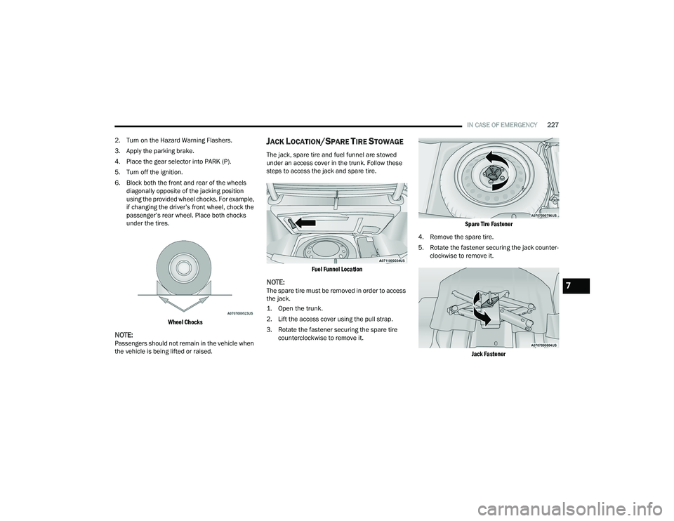
6. Block both the front and rear of the wheels diagonally opposite of the jacking position
using the provided wheel chocks. For example,
if changing the driver’s front wheel, chock the
passenger’s rear wheel. Place both chocks
under the tires.
Wheel Chocks
NOTE:Passengers should not remain in the vehicle when
the vehicle is being lifted or raised.
JACK LOCATION/SPARE TIRE STOWAGE
The jack, spare tire and fuel funnel are stowed
under an access cover in the trunk. Follow these
steps to access the jack and spare tire.
Fuel Funnel Location
NOTE:The spare tire must be removed in order to access
the jack.
1. Open the trunk.
2. Lift the access cover using the pull strap.
3. Rotate the fastener securing the spare tire counterclockwise to remove it.
Spare Tire Fastener
4. Remove the spare tire.
5. Rotate the fastener securing the jack counter -
clockwise to remove it.
Jack Fastener
7
21_LD_OM_EN_USC_t.book Page 227
Page 230 of 320
228IN CASE OF EMERGENCY
(Continued)
6. Remove the wheel chocks, jack and lug
wrench assembly from under the spare tire.
Turn the jack screw to the left to loosen the lug
wrench, and remove the wrench from the jack
assembly.
JACKING INSTRUCTIONS
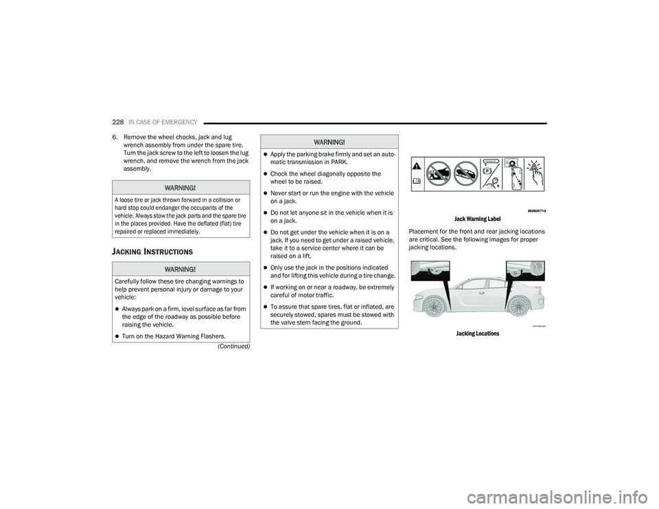
Jack Warning Label
Placement for the front and rear jacking locations
are critical. See the following images for proper
jacking locations.
Jacking Locations
WARNING!
A loose tire or jack thrown forward in a collision or
hard stop could endanger the occupants of the
vehicle. Always stow the jack parts and the spare tire
in the places provided. Have the deflated (flat) tire
repaired or replaced immediately.
WARNING!
Carefully follow these tire changing warnings to
help prevent personal injury or damage to your
vehicle:
Always park on a firm, level surface as far from
the edge of the roadway as possible before
raising the vehicle.
Turn on the Hazard Warning Flashers.
Apply the parking brake firmly and set an auto -
matic transmission in PARK.
Chock the wheel diagonally opposite the
wheel to be raised.
Never start or run the engine with the vehicle
on a jack.
Do not let anyone sit in the vehicle when it is
on a jack.
Do not get under the vehicle when it is on a
jack. If you need to get under a raised vehicle,
take it to a service center where it can be
raised on a lift.
Only use the jack in the positions indicated
and for lifting this vehicle during a tire change.
If working on or near a roadway, be extremely
careful of motor traffic.
To assure that spare tires, flat or inflated, are
securely stowed, spares must be stowed with
the valve stem facing the ground.
WARNING!
21_LD_OM_EN_USC_t.book Page 228
Page 235 of 320
IN CASE OF EMERGENCY233
SEALING A TIRE WITH TIRE SERVICE KIT
(A) Whenever You Stop To Use Tire Service Kit:
1. Pull over to a safe location and turn on the
vehicle’s Hazard Warning flashers.
2. Verify that the valve stem (on the wheel with the deflated tire) is in a position that is near to the
ground. This will allow the Tire Service Kit Hoses
(4) and (8) to reach the valve stem and keep the
Tire Service Kit flat on the ground. This will
provide the best positioning of the kit when
injecting the sealant into the deflated tire and
running the air pump. Move the vehicle as
necessary to place the valve stem in this
position before proceeding.
3. Place the transmission in PARK (auto transmission) or in Gear (manual transmission)
and place the ignition in the OFF position.
4. Apply the parking brake.
(B) Setting Up To Use Tire Service Kit:
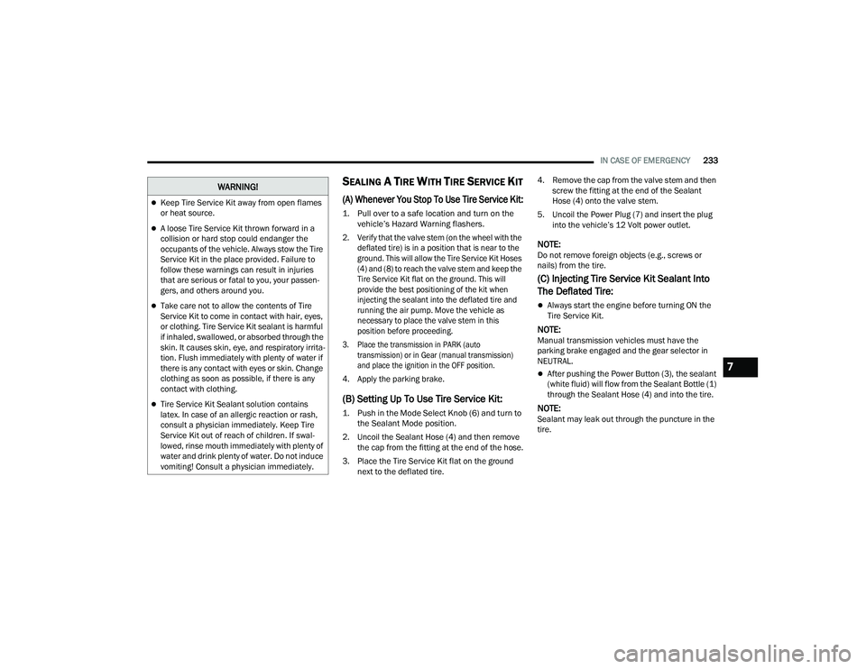
1. Push in the Mode Select Knob (6) and turn to the Sealant Mode position.
2. Uncoil the Sealant Hose (4) and then remove the cap from the fitting at the end of the hose.
3. Place the Tire Service Kit flat on the ground next to the deflated tire. 4. Remove the cap from the valve stem and then
screw the fitting at the end of the Sealant
Hose (4) onto the valve stem.
5. Uncoil the Power Plug (7) and insert the plug into the vehicle’s 12 Volt power outlet.
NOTE:Do not remove foreign objects (e.g., screws or
nails) from the tire.
(C) Injecting Tire Service Kit Sealant Into
The Deflated Tire:
Always start the engine before turning ON the
Tire Service Kit.
NOTE:Manual transmission vehicles must have the
parking brake engaged and the gear selector in
NEUTRAL.
After pushing the Power Button (3), the sealant
(white fluid) will flow from the Sealant Bottle (1)
through the Sealant Hose (4) and into the tire.
NOTE:Sealant may leak out through the puncture in the
tire.
Keep Tire Service Kit away from open flames
or heat source.
A loose Tire Service Kit thrown forward in a
collision or hard stop could endanger the
occupants of the vehicle. Always stow the Tire
Service Kit in the place provided. Failure to
follow these warnings can result in injuries
that are serious or fatal to you, your passen -
gers, and others around you.
Take care not to allow the contents of Tire
Service Kit to come in contact with hair, eyes,
or clothing. Tire Service Kit sealant is harmful
if inhaled, swallowed, or absorbed through the
skin. It causes skin, eye, and respiratory irrita -
tion. Flush immediately with plenty of water if
there is any contact with eyes or skin. Change
clothing as soon as possible, if there is any
contact with clothing.
Tire Service Kit Sealant solution contains
latex. In case of an allergic reaction or rash,
consult a physician immediately. Keep Tire
Service Kit out of reach of children. If swal -
lowed, rinse mouth immediately with plenty of
water and drink plenty of water. Do not induce
vomiting! Consult a physician immediately.
WARNING!
7
21_LD_OM_EN_USC_t.book Page 233
Page 238 of 320
236IN CASE OF EMERGENCY
JUMP STARTING
If your vehicle has a discharged battery, it can be
jump started using a set of jumper cables and a
battery in another vehicle, or by using a portable
battery booster pack. Jump starting can be
dangerous if done improperly, so please follow the
procedures in this section carefully.
NOTE:When using a portable battery booster pack, follow
the manufacturer's operating instructions and
precautions.
PREPARATIONS FOR JUMP START
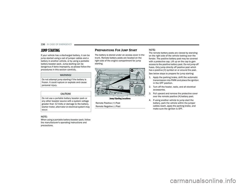
The battery is stored under an access cover in the
trunk. Remote battery posts are located on the
right side of the engine compartment for jump
starting.
Jump Starting Locations
NOTE:The remote battery posts are viewed by standing
on the right side of the vehicle looking over the
fender. The positive battery post may be covered
with a protective cap. Lift up on the cap to gain
access to the positive battery post. Do not jump off
fuses. Only jump directly off positive post which
has a positive (+) symbol on or around the post.
See below steps to prepare for jump starting:
1. Apply the parking brake, shift the automatic transmission into PARK and place the ignition
in the OFF position.
2. Turn off the heater, radio, and all electrical accessories.
3. Pull upward and remove the protective cover over the remote positive (+) battery post.
4. If using another vehicle to jump start the battery, park the vehicle within the jumper
cables reach, apply the parking brake, and
make sure the ignition is OFF.
WARNING!
Do not attempt jump starting if the battery is
frozen. It could rupture or explode and cause
personal injury.
CAUTION!
Do not use a portable battery booster pack or
any other booster source with a system voltage
greater than 12 Volts or damage to the battery,
starter motor, alternator or electrical system may
occur.
Remote Positive (+) Post
Remote Negative (-) Post
21_LD_OM_EN_USC_t.book Page 236
Page 242 of 320
240IN CASE OF EMERGENCY
MANUAL PARK RELEASE — 8-SPEED
TRANSMISSION
In order to move the vehicle in cases where the
transmission will not shift out of PARK (P) (such as
a depleted battery), a Manual Park Release is
available. Follow these steps to use the Manual Park
Release:
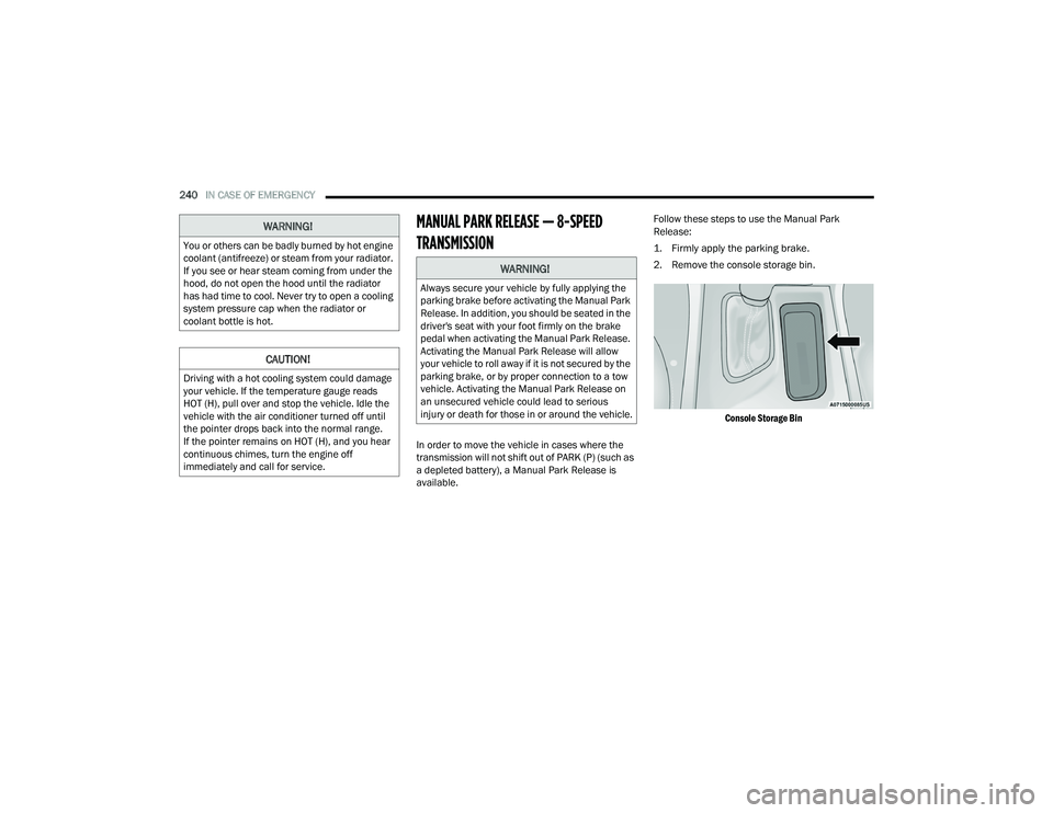
1. Firmly apply the parking brake.
2. Remove the console storage bin.
Console Storage Bin
WARNING!
You or others can be badly burned by hot engine
coolant (antifreeze) or steam from your radiator.
If you see or hear steam coming from under the
hood, do not open the hood until the radiator
has had time to cool. Never try to open a cooling
system pressure cap when the radiator or
coolant bottle is hot.
CAUTION!
Driving with a hot cooling system could damage
your vehicle. If the temperature gauge reads
HOT (H), pull over and stop the vehicle. Idle the
vehicle with the air conditioner turned off until
the pointer drops back into the normal range.
If the pointer remains on HOT (H), and you hear
continuous chimes, turn the engine off
immediately and call for service.
WARNING!
Always secure your vehicle by fully applying the
parking brake before activating the Manual Park
Release. In addition, you should be seated in the
driver's seat with your foot firmly on the brake
pedal when activating the Manual Park Release.
Activating the Manual Park Release will allow
your vehicle to roll away if it is not secured by the
parking brake, or by proper connection to a tow
vehicle. Activating the Manual Park Release on
an unsecured vehicle could lead to serious
injury or death for those in or around the vehicle.
21_LD_OM_EN_USC_t.book Page 240
Page 243 of 320
IN CASE OF EMERGENCY241
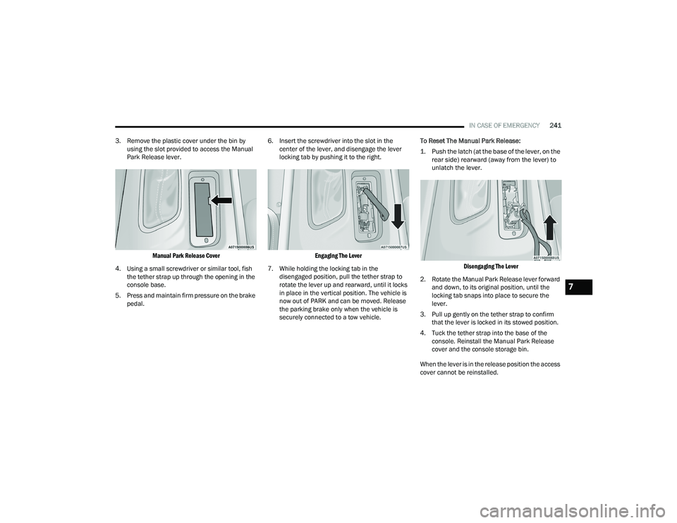
3. Remove the plastic cover under the bin by using the slot provided to access the Manual
Park Release lever.
Manual Park Release Cover
4. Using a small screwdriver or similar tool, fish the tether strap up through the opening in the
console base.
5. Press and maintain firm pressure on the brake pedal. 6. Insert the screwdriver into the slot in the
center of the lever, and disengage the lever
locking tab by pushing it to the right.
Engaging The Lever
7. While holding the locking tab in the disengaged position, pull the tether strap to
rotate the lever up and rearward, until it locks
in place in the vertical position. The vehicle is
now out of PARK and can be moved. Release
the parking brake only when the vehicle is
securely connected to a tow vehicle. To Reset The Manual Park Release:
1. Push the latch (at the base of the lever, on the
rear side) rearward (away from the lever) to
unlatch the lever.
Disengaging The Lever
2. Rotate the Manual Park Release lever forward and down, to its original position, until the
locking tab snaps into place to secure the
lever.
3. Pull up gently on the tether strap to confirm that the lever is locked in its stowed position.
4. Tuck the tether strap into the base of the console. Reinstall the Manual Park Release
cover and the console storage bin.
When the lever is in the release position the access
cover cannot be reinstalled.
7
21_LD_OM_EN_USC_t.book Page 241