wheel bolts DODGE CHARGER 2023 Owners Manual
[x] Cancel search | Manufacturer: DODGE, Model Year: 2023, Model line: CHARGER, Model: DODGE CHARGER 2023Pages: 292, PDF Size: 13.05 MB
Page 191 of 292

SAFETY189
(Continued)
Your vehicle may also be designed to perform any of these
other functions in response to the Enhanced Accident
Response System:
Turn off the Fuel Filter Heater, Turn off the HVAC Blower
Motor, Close the HVAC Circulation Door
Cut off battery power to the:
Engine
Electric Motor (if equipped)
Electric power steering
Brake booster
Electric park brake
Automatic transmission gear selector
Horn
Front wiper
NOTE:After an accident, remember to cycle the ignition to the
STOP (OFF/LOCK) position and remove the key from the
ignition switch to avoid draining the battery. Carefully
check the vehicle for fuel leaks in the engine compartment
and on the ground near the engine compartment and fuel
tank before resetting the system and starting the engine.
If there are no fuel leaks or damage to the vehicle elec -
trical devices (e.g. headlights) after an accident, reset the
system by following the procedure described below. If you
have any doubt, contact an authorized dealer.
Enhanced Accident Response System
Reset Procedure
In order to reset the Enhanced Accident Response System
functions after an event, the ignition switch must be
changed from ignition START or ON/RUN to ignition OFF.
Carefully check the vehicle for fuel leaks in the engine
compartment and on the ground near the engine
compartment and fuel tank before resetting the system
and starting the engine.
After an accident, if the vehicle will not start after
performing the reset procedure, the vehicle must be
towed to an authorized dealer to be inspected and to have
the Enhanced Accident Response System reset.
Maintaining Your Air Bag System Event Data Recorder (EDR)
This vehicle is equipped with an event data recorder
(EDR). The main purpose of an EDR is to record, in certain
crash or near crash-like situations, such as an air bag
deployment or hitting a road obstacle, data that will assist
in understanding how a vehicle’s systems performed. The
EDR is designed to record data related to vehicle
dynamics and safety systems for a short period of time,
typically 30 seconds or less. The EDR in this vehicle is
designed to record such data as:
How various systems in your vehicle were operating;
Whether or not the driver and passenger safety belts
were buckled/fastened;
How far (if at all) the driver was depressing the acceler -
ator and/or brake pedal; and,
How fast the vehicle was traveling.WARNING!
Modifications to any part of the air bag system could
cause it to fail when you need it. You could be injured
if the air bag system is not there to protect you. Do
not modify the components or wiring, including
adding any kind of badges or stickers to the steering
wheel hub trim cover or the upper passenger side of
the instrument panel. Do not modify the front fascia/
bumper, vehicle body structure, or add aftermarket
side steps or running boards.
It is dangerous to try to repair any part of the air bag
system yourself. Be sure to tell anyone who works on
your vehicle that it has an air bag system.
Do not attempt to modify any part of your air bag
system. The air bag may inflate accidentally or may
not function properly if modifications are made. Take
your vehicle to an authorized dealer for any air bag
system service. If your seat, including your trim cover
and cushion, needs to be serviced in any way
(including removal or loosening/tightening of seat
attachment bolts), take the vehicle to an authorized
dealer. Only manufacturer approved seat accesso -
ries may be used. If it is necessary to modify the air
bag system for persons with disabilities, contact an
authorized dealer.
WARNING!
6
23_LD_OM_EN_USC_t.book Page 189
Page 211 of 292

IN CASE OF EMERGENCY209
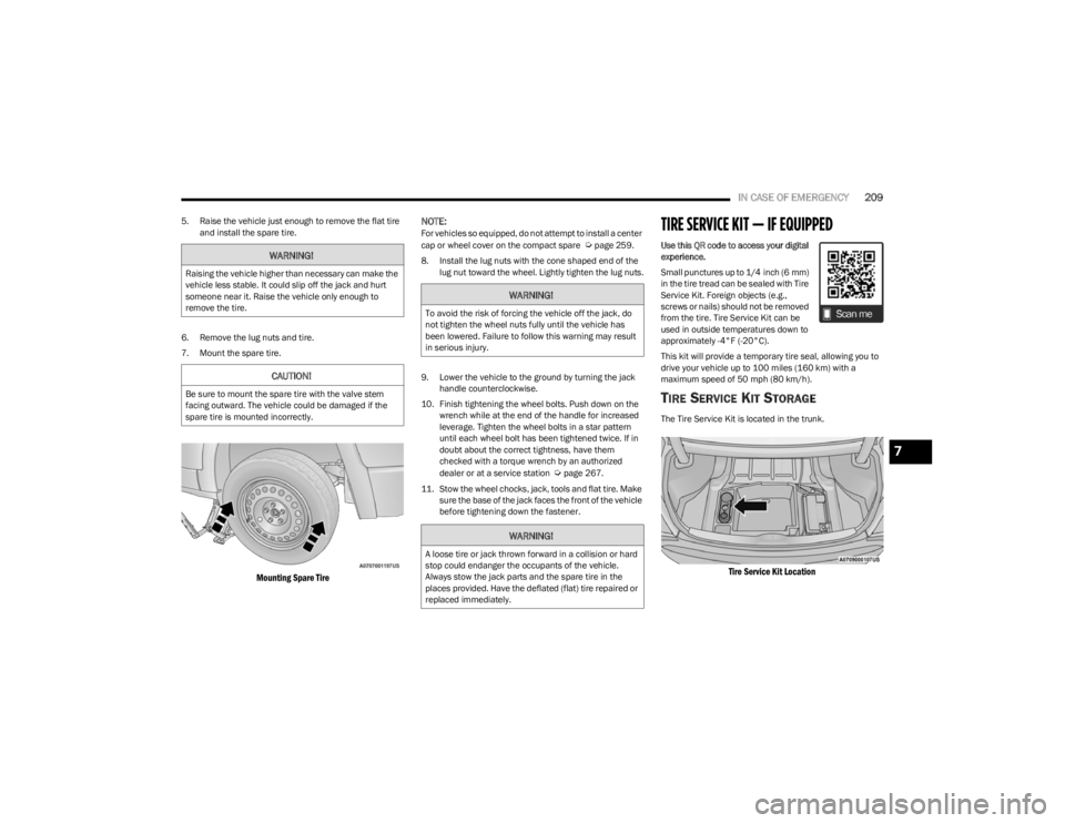
5. Raise the vehicle just enough to remove the flat tire
and install the spare tire.
6. Remove the lug nuts and tire.
7. Mount the spare tire.
Mounting Spare Tire
NOTE:
For vehicles so equipped, do not attempt to install a center
cap or wheel cover on the compact spare Úpage 259.
8. Install the lug nuts with the cone shaped end of the lug nut toward the wheel. Lightly tighten the lug nuts.
9. Lower the vehicle to the ground by turning the jack handle counterclockwise.
10. Finish tightening the wheel bolts. Push down on the wrench while at the end of the handle for increased
leverage. Tighten the wheel bolts in a star pattern
until each wheel bolt has been tightened twice. If in
doubt about the correct tightness, have them
checked with a torque wrench by an authorized
dealer or at a service station
Úpage 267.
11. Stow the wheel chocks, jack, tools and flat tire. Make sure the base of the jack faces the front of the vehicle
before tightening down the fastener.
TIRE SERVICE KIT — IF EQUIPPED
Use this QR code to access your digital
experience.
Small punctures up to 1/4 inch (6 mm)
in the tire tread can be sealed with Tire
Service Kit. Foreign objects (e.g.,
screws or nails) should not be removed
from the tire. Tire Service Kit can be
used in outside temperatures down to
approximately -4°F (-20°C).
This kit will provide a temporary tire seal, allowing you to
drive your vehicle up to 100 miles (160 km) with a
maximum speed of 50 mph (80 km/h).
TIRE SERVICE KIT STORAGE
The Tire Service Kit is located in the trunk.
Tire Service Kit Location
WARNING!
Raising the vehicle higher than necessary can make the
vehicle less stable. It could slip off the jack and hurt
someone near it. Raise the vehicle only enough to
remove the tire.
CAUTION!
Be sure to mount the spare tire with the valve stem
facing outward. The vehicle could be damaged if the
spare tire is mounted incorrectly.
WARNING!
To avoid the risk of forcing the vehicle off the jack, do
not tighten the wheel nuts fully until the vehicle has
been lowered. Failure to follow this warning may result
in serious injury.
WARNING!
A loose tire or jack thrown forward in a collision or hard
stop could endanger the occupants of the vehicle.
Always stow the jack parts and the spare tire in the
places provided. Have the deflated (flat) tire repaired or
replaced immediately.
7
23_LD_OM_EN_USC_t.book Page 209
Page 269 of 292

267
TECHNICAL SPECIFICATIONS
VEHICLE IDENTIFICATION NUMBER (VIN)
The VIN is on the left front corner of the instrument panel.
The VIN is visible from outside of the vehicle through the
windshield.
Windshield VIN Location
NOTE:
It is illegal to remove or alter the VIN.
BRAKE SYSTEM
Your vehicle is equipped with dual hydraulic brake
systems. If either of the two hydraulic systems lose normal
capability, the remaining system will still function. There
will be some loss of overall braking effectiveness. This
may be evident by increased pedal travel during
application, greater pedal force required to slow or stop,
and potential activation of the Brake Warning Light.
In the event power assist is lost for any reason (for
example, repeated brake applications with the engine off),
the brakes will still function. The effort required to brake
the vehicle will be much greater than that required with
the power system operating.
WHEEL AND TIRE TORQUE SPECIFICATIONS
Proper lug nut/bolt torque is very important to ensure that
the wheel is properly mounted to the vehicle. Any time a
wheel has been removed and reinstalled on the vehicle,
the lug nuts/bolts should be torqued using a properly
calibrated torque wrench using a six-sided (hex)
deep wall socket.
TORQUE SPECIFICATIONS
**Use only authorized dealer recommended lug
nuts/bolts and clean or remove any dirt or oil before
tightening.
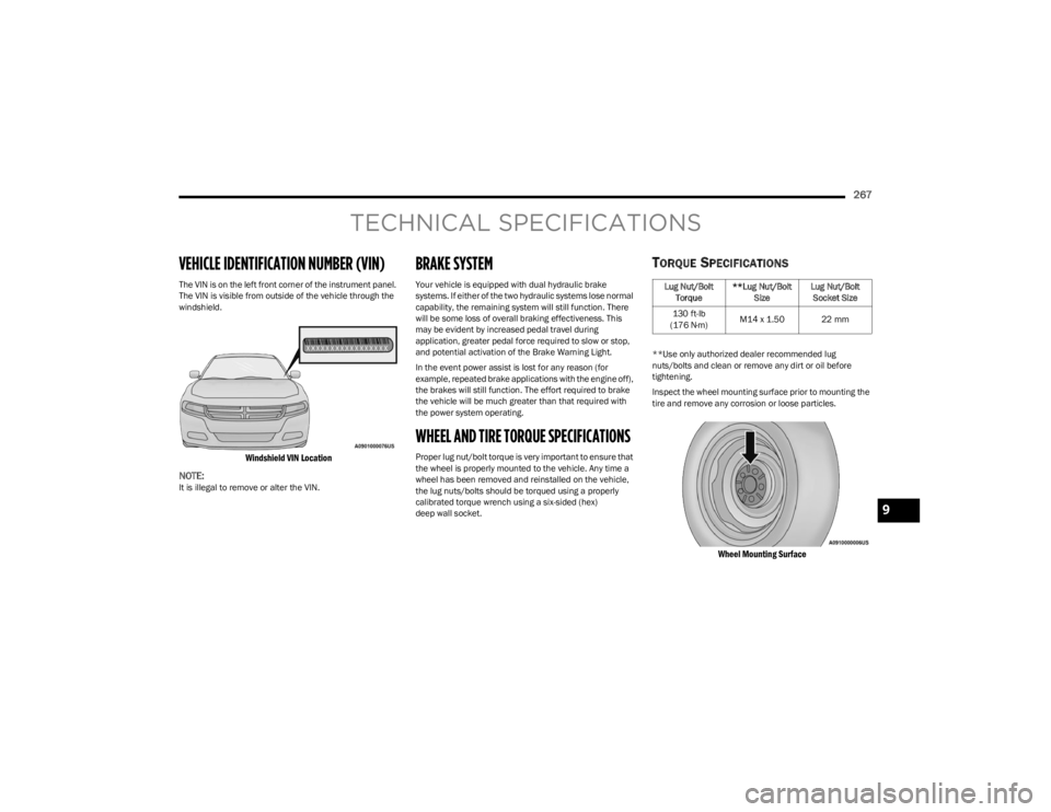
Inspect the wheel mounting surface prior to mounting the
tire and remove any corrosion or loose particles.
Wheel Mounting Surface
Lug Nut/Bolt Torque **Lug Nut/Bolt
Size Lug Nut/Bolt
Socket Size
130 ft-lb
(176 N·m) M14 x 1.50 22 mm
9
23_LD_OM_EN_USC_t.book Page 267