DODGE CHARGER SRT 2015 7.G Owners Manual
Manufacturer: DODGE, Model Year: 2015, Model line: CHARGER SRT, Model: DODGE CHARGER SRT 2015 7.GPages: 595, PDF Size: 16.43 MB
Page 141 of 595
WARNING!
•Be certain that the seatback is securely locked into
position. If the seatback is not securely locked into
position, the seat will not provide the proper sta-
bility for child seats and/or passengers. An improp-
erly latched seat could cause serious injury.
•The cargo area in the rear of the vehicle (with the
rear seatbacks in the locked-up or folded down
position) should not be used as a play area by
children when the vehicle is in motion. They could
be seriously injured in a collision. Children should
be seated and using the proper restraint system.
DRIVER MEMORY SEAT — IF EQUIPPED
This feature allows the driver to store up to two different
memory profiles for easy recall through a memory
switch. Each memory profile contains desired position
settings for the driver seat, side mirrors, adjustable
pedals (if equipped), and power tilt and telescopic steer-
ing column (if equipped) and a set of desired radio
station presets. Your Remote Keyless Entry (RKE) trans-
mitter can also be programmed to recall the same posi-
tions when the UNLOCK button is pushed.
NOTE:If your vehicle is equipped with two RKE trans-
mitters, one RKE transmitter can be linked to memory
position 1 and the other transmitter can be linked to
memory position 2.
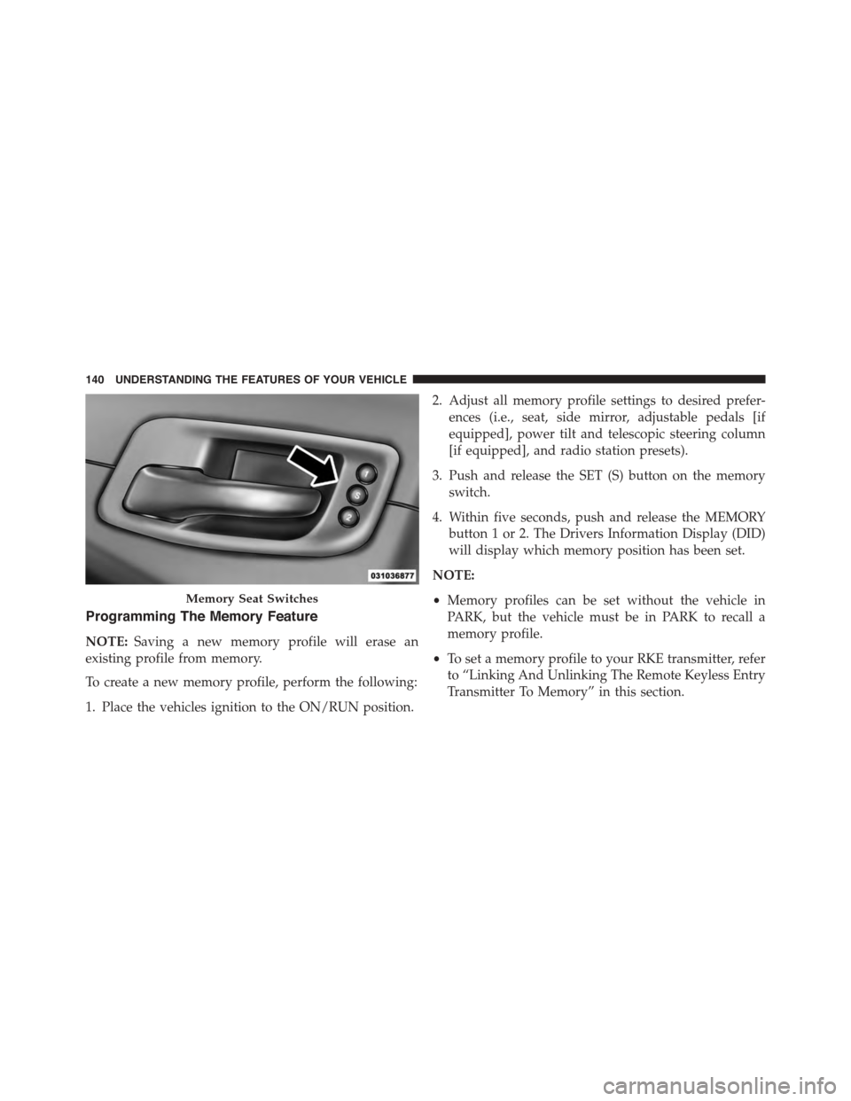
The memory seat switch is located on the driver ’s door
trim panel. The switch consists of three buttons: The (S)
button, which is used to activate the memory save
function and the (1) and (2) buttons which are used to
recall either of two pre-programmed memory profiles.
3
UNDERSTANDING THE FEATURES OF YOUR VEHICLE 139
Page 142 of 595
Programming The Memory Feature
NOTE:Saving a new memory profile will erase an
existing profile from memory.
To create a new memory profile, perform the following:
1. Place the vehicles ignition to the ON/RUN position.
2. Adjust all memory profile settings to desired prefer-
ences (i.e., seat, side mirror, adjustable pedals [if
equipped], power tilt and telescopic steering column
[if equipped], and radio station presets).
3. Push and release the SET (S) button on the memory
switch.
4. Within five seconds, push and release the MEMORY
button 1 or 2. The Drivers Information Display (DID)
will display which memory position has been set.
NOTE:
•Memory profiles can be set without the vehicle in
PARK, but the vehicle must be in PARK to recall a
memory profile.
•To set a memory profile to your RKE transmitter, refer
to “Linking And Unlinking The Remote Keyless Entry
Transmitter To Memory” in this section.
Memory Seat Switches
140 UNDERSTANDING THE FEATURES OF YOUR VEHICLE
Page 143 of 595
Linking And Unlinking The Remote Keyless Entry
Transmitter To Memory
Your RKE transmitters can be programmed to recall one
of two pre-programmed memory profiles by pushing the
UNLOCK button on the RKE transmitter.
NOTE:Before programming your RKE transmitters you
must select the “Memory To FOB” or “Personal Settings
Linked To Fob” feature through the Uconnect® system
screen. Refer to “Uconnect® Settings” in “Understanding
Your Instrument Panel” for further information.
To program your RKE transmitters, perform the follow-
ing:
1. Place the vehicles ignition to the OFF position.
2. Select desired memory profile (1) or (2). The system
will recall any stored settings for this profile. Wait for
the system to complete the memory recall before
continuing to Step 3.
NOTE:If a memory profile has not already been set,
refer to#Programming The Memory Feature#in this
section for instructions on how to set a memory profile.
3. Once the profile has been recalled, push and release
the SET (S) button on the memory switch, then push
and release button (1) or (2) accordingly. “Memory
Profile Set” (1 or 2) will display in the Drivers Infor-
mation Display (DID).
4. Push and release the LOCK button on the RKE trans-
mitter within 10 seconds.
NOTE:Your RKE transmitters can be unlinked from
your memory settings by pushing the SET (S) button, and
within 10 seconds, followed by pushing the UNLOCK
button on the RKE transmitter.
3
UNDERSTANDING THE FEATURES OF YOUR VEHICLE 141
Page 144 of 595

Memory Position Recall
NOTE:The vehicle must be in PARK to recall memory
positions. If a recall is attempted when the vehicle is not
in PARK, a message will display in the Drivers Informa-
tion Display (DID).
To recall the memory settings for driver 1, push
MEMORY button number 1 on the driver’s door or the
UNLOCK button on the RKE transmitter linked to
memory position 1.
NOTE:If the vehicle is equipped with Passive Entry, the
memory settings will be recalled with a Passive Entry
Unlock into the driver’s door using the Key Fob linked to
position 1.
To recall the memory setting for driver 2, push MEMORY
button number 2 on the driver’s door or the UNLOCK
button on the RKE transmitter linked to memory position
2.
NOTE:If the vehicle is equipped with Passive Entry, the
memory settings will be recalled with a Passive Entry
Unlock into the driver’s door using the Key Fob linked to
position 2.
A recall can be cancelled by pushing any of the MEMORY
buttons (S, 1, or 2) on the driver’s door during a recall.
When a recall is cancelled, the driver’s seat, adjustable
pedals (if equipped), and power tilt and telescopic steer-
ing column (if equipped) stop moving. A delay of one
second will occur before another recall can be selected.
Easy Entry/Exit Seat
This feature provides automatic driver seat positioning to
enhance driver mobility when entering and exiting the
vehicle.
The distance the driver seat moves depends on where
you have the driver seat positioned when you cycle the
vehicles ignition to the OFF position.
142 UNDERSTANDING THE FEATURES OF YOUR VEHICLE
Page 145 of 595
•When you cycle the vehicles ignition to the OFF
position, the driver seat will move about 2.4 in (60
mm) rearward if the driver seat position is greater than
or equal to 2.7 in (67.7 mm) forward of the rear stop.
The seat will return to its previously set position when
you cycle the vehicles ignition to the ACC or RUN
position.
•The Easy Entry/Easy Exit feature is disabled when the
driver seat position is less than 0.9 in (22.7 mm)
forward of the rear stop. At this position, there is no
benefit to the driver by moving the seat for Easy Exit
or Easy Entry.
Each stored memory setting will have an associated Easy
Entry and Easy Exit position.
NOTE:The Easy Entry/Exit feature is not enabled when
the vehicle is delivered from the factory. The Easy
Entry/Exit feature is enabled (or later disabled) through
the programmable features in the Uconnect® system.
Refer to “Uconnect® Settings/Customer Programmable
Features” in “Understanding Your Instrument Panel” for
further information.
3
UNDERSTANDING THE FEATURES OF YOUR VEHICLE 143
Page 146 of 595
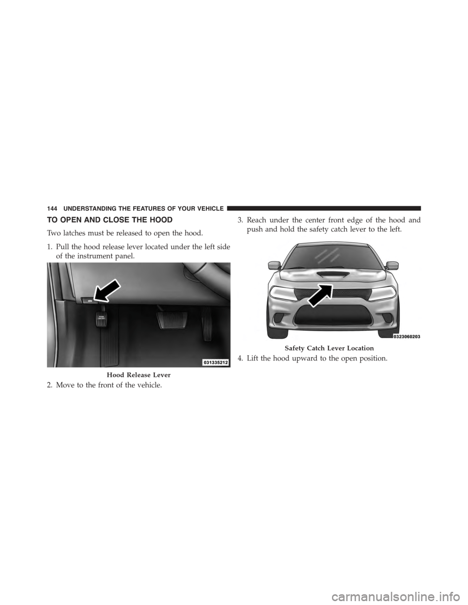
TO OPEN AND CLOSE THE HOOD
Two latches must be released to open the hood.
1. Pull the hood release lever located under the left side
of the instrument panel.
2. Move to the front of the vehicle.
3. Reach under the center front edge of the hood and
push and hold the safety catch lever to the left.
4. Lift the hood upward to the open position.
Hood Release Lever
Safety Catch Lever Location
144 UNDERSTANDING THE FEATURES OF YOUR VEHICLE
Page 147 of 595
CAUTION!
To prevent possible damage, do not slam the hood to
close it. Lower the hood until it is open approxi-
mately 6 inches (15 cm), and then drop it. This should
secure both latches. Never drive your vehicle unless
the hood is fully closed, with both latches engaged.
WARNING!
Be sure the hood is fully latched before driving your
vehicle. If the hood is not fully latched, it could open
when the vehicle is in motion and block your vision.
Failure to follow this warning could result in serious
injury or death.
LIGHTS
Headlight Switch
The headlight switch is located on the left side of
the instrument panel. This switch controls the
operation of the headlights, parking lights, instru-
ment panel lights, instrument panel light dimming, inte-
rior lights and fog lights (if equipped).
3
UNDERSTANDING THE FEATURES OF YOUR VEHICLE 145
Page 148 of 595
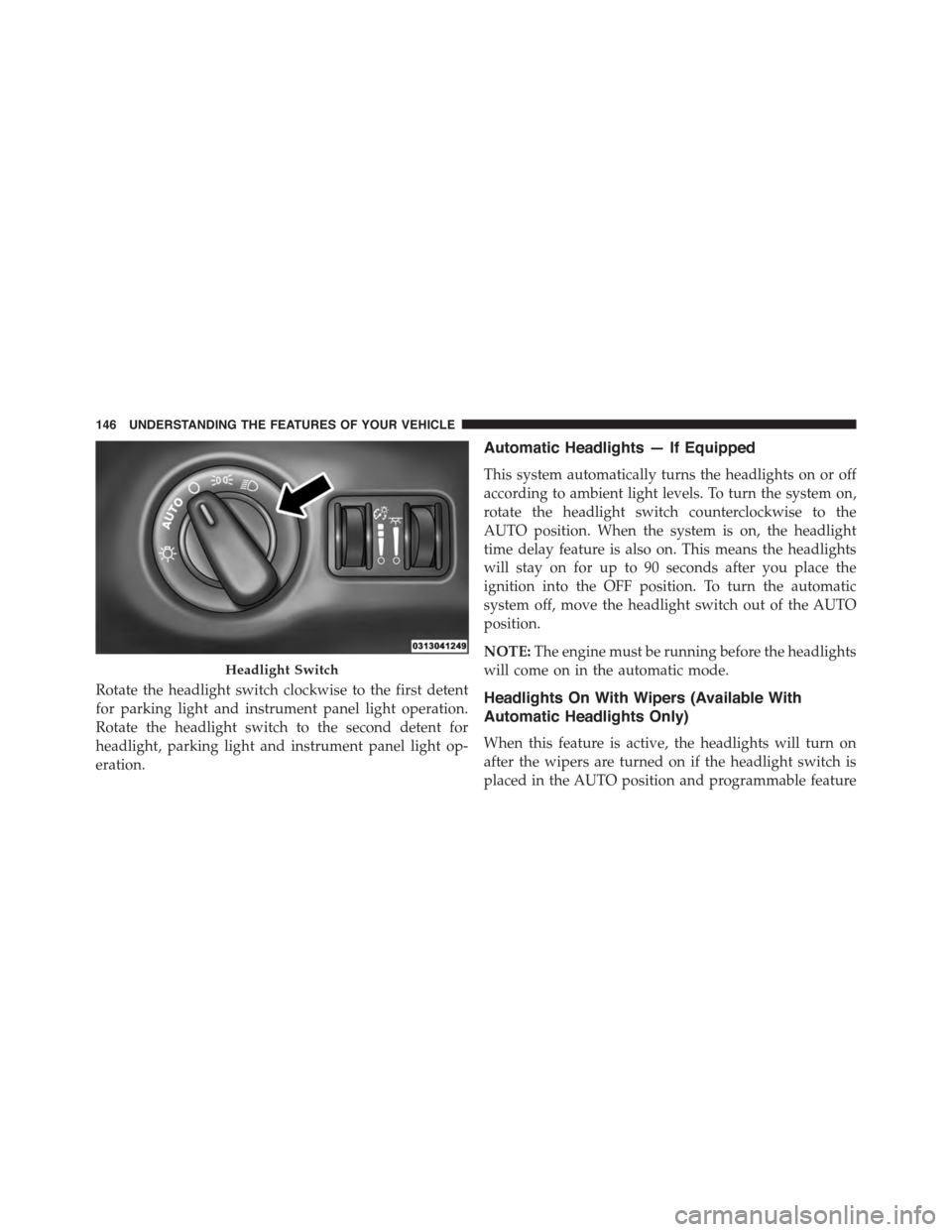
Rotate the headlight switch clockwise to the first detent
for parking light and instrument panel light operation.
Rotate the headlight switch to the second detent for
headlight, parking light and instrument panel light op-
eration.
Automatic Headlights — If Equipped
This system automatically turns the headlights on or off
according to ambient light levels. To turn the system on,
rotate the headlight switch counterclockwise to the
AUTO position. When the system is on, the headlight
time delay feature is also on. This means the headlights
will stay on for up to 90 seconds after you place the
ignition into the OFF position. To turn the automatic
system off, move the headlight switch out of the AUTO
position.
NOTE:The engine must be running before the headlights
will come on in the automatic mode.
Headlights On With Wipers (Available With
Automatic Headlights Only)
When this feature is active, the headlights will turn on
after the wipers are turned on if the headlight switch is
placed in the AUTO position and programmable feature
Headlight Switch
146 UNDERSTANDING THE FEATURES OF YOUR VEHICLE
Page 149 of 595
is set to ON. In addition, the headlights will turn off
when the wipers are turned off if they were turned on by
this feature.
NOTE:The Headlights On with Wipers feature can be
turned on or off using the Uconnect® System. Refer to
“Uconnect® Settings/Customer Programmable Fea-
tures” in “Understanding Your Instrument Panel” for
further information.
Automatic High Beam Headlamp Control — If
Equipped
The Automatic High Beam Headlamp Control system
provides increased forward lighting at night by automat-
ing high beam control through the use of a digital camera
mounted on the windshield. This camera detects vehicle
specific light and automatically switches from high
beams to low beams until the approaching vehicle is out
of view.
NOTE:
•The Automatic High Beam Headlamp Control can be
turned on or off using the Uconnect® System. Refer to
“Uconnect® Settings” in “Understanding Your Instru-
ment Panel” for further information.
•Broken, muddy, or obstructed headlights and taillights
of vehicles in the field of view will cause headlights to
remain on longer (closer to the vehicle). Also, dirt, film,
and other obstructions on the windshield or camera
lens will cause the system to function improperly.
If the windshield or Automatic High Beam Headlamp
Control mirror is replaced, the mirror must be re-aimed
to ensure proper performance. See your local authorized
dealer.
To Activate
1. Turn the headlight switch to the AUTO headlight
position.
3
UNDERSTANDING THE FEATURES OF YOUR VEHICLE 147
Page 150 of 595
2. Push the multifunction lever away from you (toward
front of vehicle) to engage the high beam mode.
NOTE:This system will not activate until the vehicle is
at or above 15 mph (24 km/h).
To Deactivate
1. Pull the multifunction lever toward you (or rearward
in car) to manually deactivate the system (normal
operation of low beams).
2. Push back on the multifunction lever to reactivate the
system.
Headlight Time Delay
This feature provides the safety of headlight illumination
for up to 90 seconds when leaving your vehicle in an
unlit area.
To activate the delay feature, turn OFF the ignition switch
while the headlights are still on. Then, turn off the
headlights within 45 seconds. The delay interval begins
when the headlight switch is turned off.
NOTE:The lights must be turned off within 45 seconds
of turning the ignition OFF to activate this feature.
If you turn the headlights, park lights or ignition switch
ON again, the system will cancel the delay.
If you turn the headlights off before the ignition, they will
turn off in the normal manner.
NOTE:The Headlight Time Delay is programmable us-
ing the Uconnect® System, refer to “Uconnect® Settings”
in “Understanding Your Instrument Panel” for further
information.
148 UNDERSTANDING THE FEATURES OF YOUR VEHICLE