sport mode DODGE CHARGER SRT 2015 7.G Owners Manual
[x] Cancel search | Manufacturer: DODGE, Model Year: 2015, Model line: CHARGER SRT, Model: DODGE CHARGER SRT 2015 7.GPages: 595, PDF Size: 16.43 MB
Page 96 of 595
5. Remove slack in the tether strap according to the child
restraint manufacturer ’s instructions.
WARNING!
•An incorrectly anchored tether strap could lead to
increased head motion and possible injury to the
child. Use only the anchorage position directly
behind the child seat to secure a child restraint top
tether strap.
•If your vehicle is equipped with a split rear seat,
make sure the tether strap does not slip into the
opening between the seatbacks as you remove
slack in the strap.
Transporting Pets
Air Bags deploying in the front seat could harm your pet.
An unrestrained pet will be thrown about and possibly
injured, or injure a passenger during panic braking or in
a collision.
Pets should be restrained in the rear seat in pet harnesses
or pet carriers that are secured by seat belts.
SRT ENGINE BREAK-IN RECOMMENDATIONS
SRT Engine Break-In Recommendations: The following
tips will be helpful in obtaining optimum performance
and maximum durability for your new SRT Vehicle.
Despite modern technology and World Class manufac-
turing methods, the moving parts of the vehicle must still
wear in with each other. This wearing in occurs mainly
during the first 500 miles (805 km) and continues through
the first oil change interval.
94 THINGS TO KNOW BEFORE STARTING YOUR VEHICLE
Page 123 of 595
The BSM detection zone covers approximately one lane
width on both sides of the vehicle 12 ft (3.8 m). The zone
length starts at the outside rear view mirror and extends
approximately 10 ft (3 m) beyond the rear bumper of the
vehicle. The BSM system monitors the detection zones on
both sides of the vehicle when the vehicle speed reaches
approximately 6 mph (10 km/h) or higher and will alert
the driver of vehicles in these areas.
NOTE:
•The BSM system does NOT alert the driver about
rapidly approaching vehicles that are outside the de-
tection zones.
•The BSM system detection zone DOES NOT change if
your vehicle is towing a trailer. Therefore, visually
verify the adjacent lane is clear for both your vehicle
and trailer before making a lane change. If the trailer or
other object (i.e., bicycle, sports equipment) extends
beyond the side of your vehicle, this may result in the
BSM warning light remaining illuminated the entire
time the vehicle is in a forward gear.
The area on the rear fascia where the radar sensors are
located must remain free of snow, ice, and dirt/road
contamination so that the BSM system can function
properly. Do not block the area of the rear fascia where
the radar sensors are located with foreign objects (bum-
per stickers, bicycle racks, etc.).
The BSM system notifies the driver of objects in the
detection zones by illuminating the BSM warning light
located in the outside mirrors in addition to sounding an
audible (chime) alert and reducing the radio volume.
Refer to “Modes Of Operation” for further information.
The BSM system monitors the detection zone from three
different entry points (side, rear, front) while driving to
see if an alert is necessary. The BSM system will issue an
alert during these types of zone entries.
3
UNDERSTANDING THE FEATURES OF YOUR VEHICLE 121
Page 258 of 595
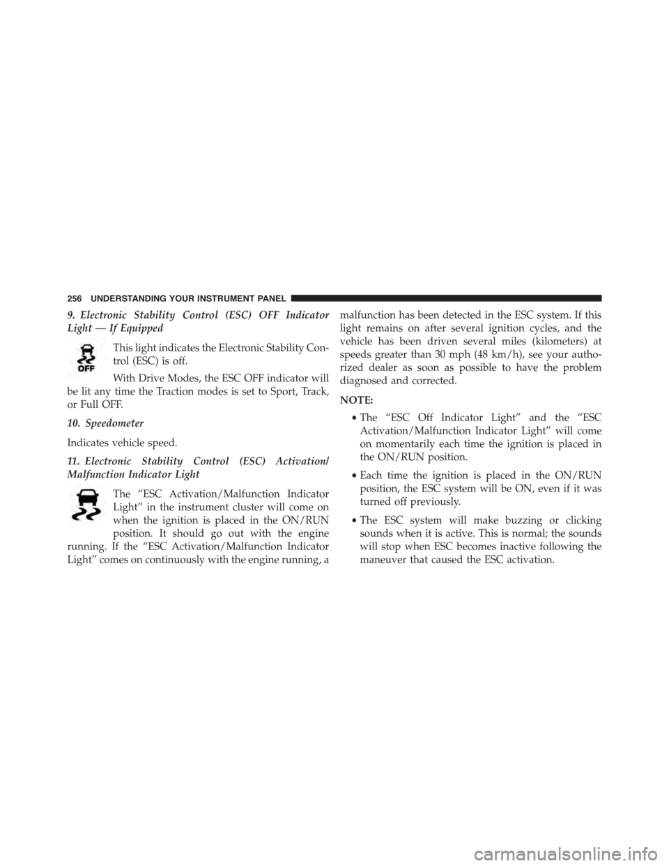
9. Electronic Stability Control (ESC) OFF Indicator
Light — If Equipped
This light indicates the Electronic Stability Con-
trol (ESC) is off.
With Drive Modes, the ESC OFF indicator will
be lit any time the Traction modes is set to Sport, Track,
or Full OFF.
10. Speedometer
Indicates vehicle speed.
11. Electronic Stability Control (ESC) Activation/
Malfunction Indicator Light
The “ESC Activation/Malfunction Indicator
Light” in the instrument cluster will come on
when the ignition is placed in the ON/RUN
position. It should go out with the engine
running. If the “ESC Activation/Malfunction Indicator
Light” comes on continuously with the engine running, a
malfunction has been detected in the ESC system. If this
light remains on after several ignition cycles, and the
vehicle has been driven several miles (kilometers) at
speeds greater than 30 mph (48 km/h), see your autho-
rized dealer as soon as possible to have the problem
diagnosed and corrected.
NOTE:
•The “ESC Off Indicator Light” and the “ESC
Activation/Malfunction Indicator Light” will come
on momentarily each time the ignition is placed in
the ON/RUN position.
•Each time the ignition is placed in the ON/RUN
position, the ESC system will be ON, even if it was
turned off previously.
•The ESC system will make buzzing or clicking
sounds when it is active. This is normal; the sounds
will stop when ESC becomes inactive following the
maneuver that caused the ESC activation.
256 UNDERSTANDING YOUR INSTRUMENT PANEL
Page 308 of 595
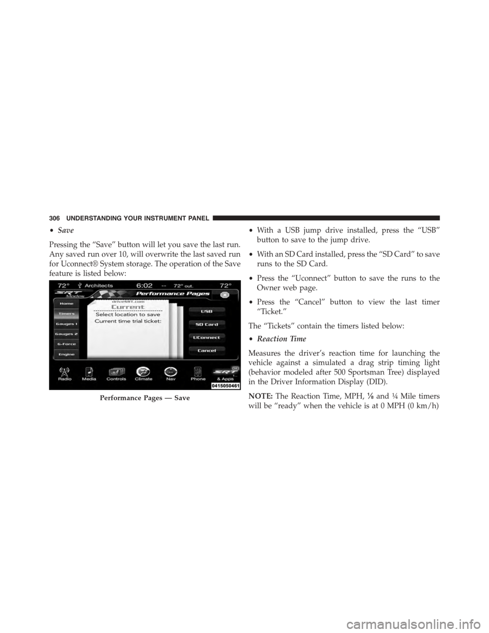
•Save
Pressing the “Save” button will let you save the last run.
Any saved run over 10, will overwrite the last saved run
for Uconnect® System storage. The operation of the Save
feature is listed below:
•With a USB jump drive installed, press the “USB”
button to save to the jump drive.
•With an SD Card installed, press the “SD Card” to save
runs to the SD Card.
•Press the “Uconnect” button to save the runs to the
Owner web page.
•Press the “Cancel” button to view the last timer
“Ticket.”
The “Tickets” contain the timers listed below:
•Reaction Time
Measures the driver’s reaction time for launching the
vehicle against a simulated a drag strip timing light
(behavior modeled after 500 Sportsman Tree) displayed
in the Driver Information Display (DID).
NOTE:The Reaction Time, MPH,⅛and¼Mile timers
will be “ready” when the vehicle is at 0 MPH (0 km/h)
Performance Pages — Save
306 UNDERSTANDING YOUR INSTRUMENT PANEL
Page 318 of 595
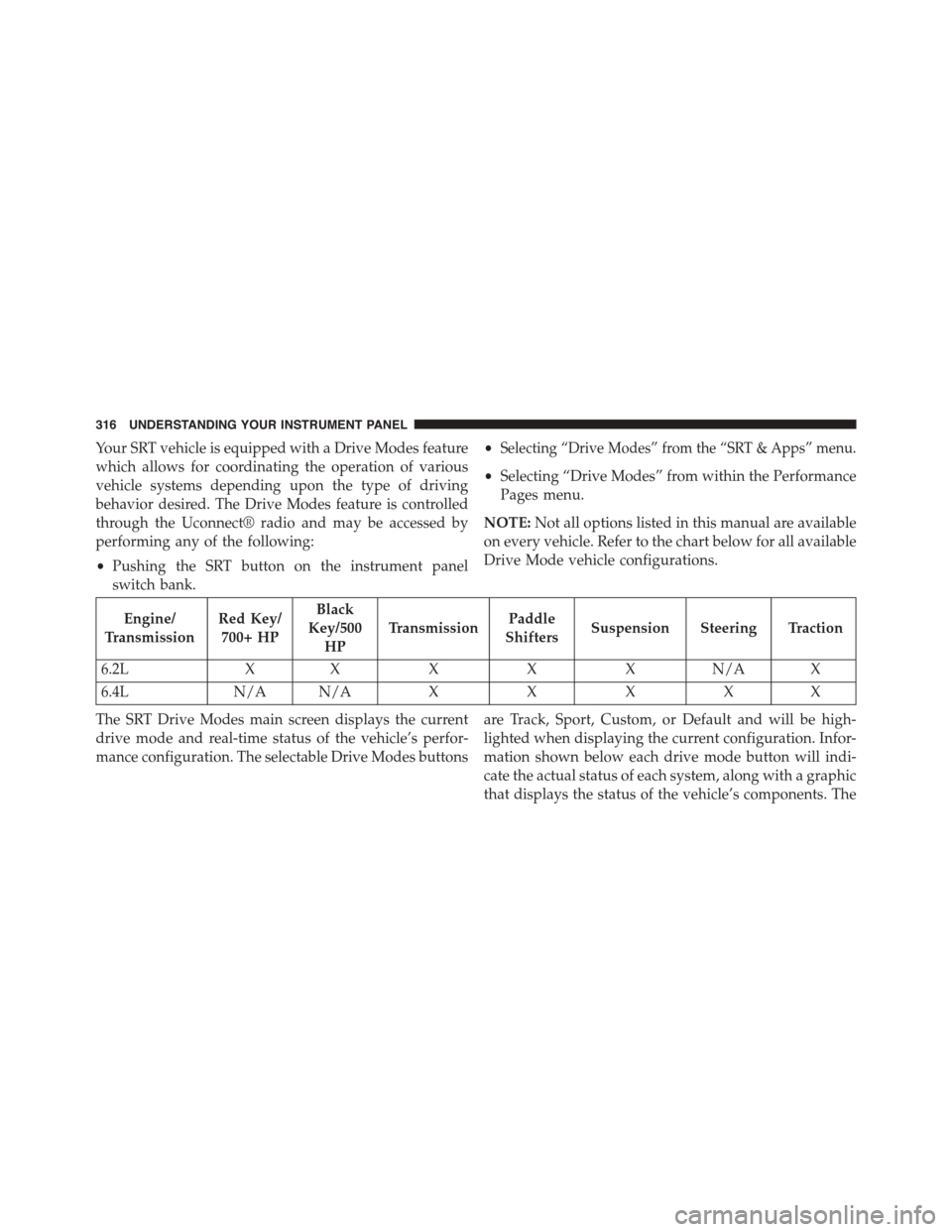
Your SRT vehicle is equipped with a Drive Modes feature
which allows for coordinating the operation of various
vehicle systems depending upon the type of driving
behavior desired. The Drive Modes feature is controlled
through the Uconnect® radio and may be accessed by
performing any of the following:
•Pushing the SRT button on the instrument panel
switch bank.
•Selecting “Drive Modes” from the “SRT & Apps” menu.
•Selecting “Drive Modes” from within the Performance
Pages menu.
NOTE:Not all options listed in this manual are available
on every vehicle. Refer to the chart below for all available
Drive Mode vehicle configurations.
Engine/
Transmission
Red Key/
700+ HP
Black
Key/500
HP
TransmissionPaddle
ShiftersSuspension Steering Traction
6.2LXXXXXN/AX
6.4LN/A N/AXXXXX
The SRT Drive Modes main screen displays the current
drive mode and real-time status of the vehicle’s perfor-
mance configuration. The selectable Drive Modes buttons
are Track, Sport, Custom, or Default and will be high-
lighted when displaying the current configuration. Infor-
mation shown below each drive mode button will indi-
cate the actual status of each system, along with a graphic
that displays the status of the vehicle’s components. The
316 UNDERSTANDING YOUR INSTRUMENT PANEL
Page 319 of 595
color red indicates “Track,” orange “Sport,” and yellow
“Street.” If the system status shown does not match the
current drive mode set up, a message will be displayed
indicating which values are not matching the current
mode and why.
NOTE:ESC Full-Off can be activated across all of the
Drive Mode features by pushing and holding the ESC Off
button on the instrument panel switch bank for five
seconds.
Listed below are the available Drive Modes:
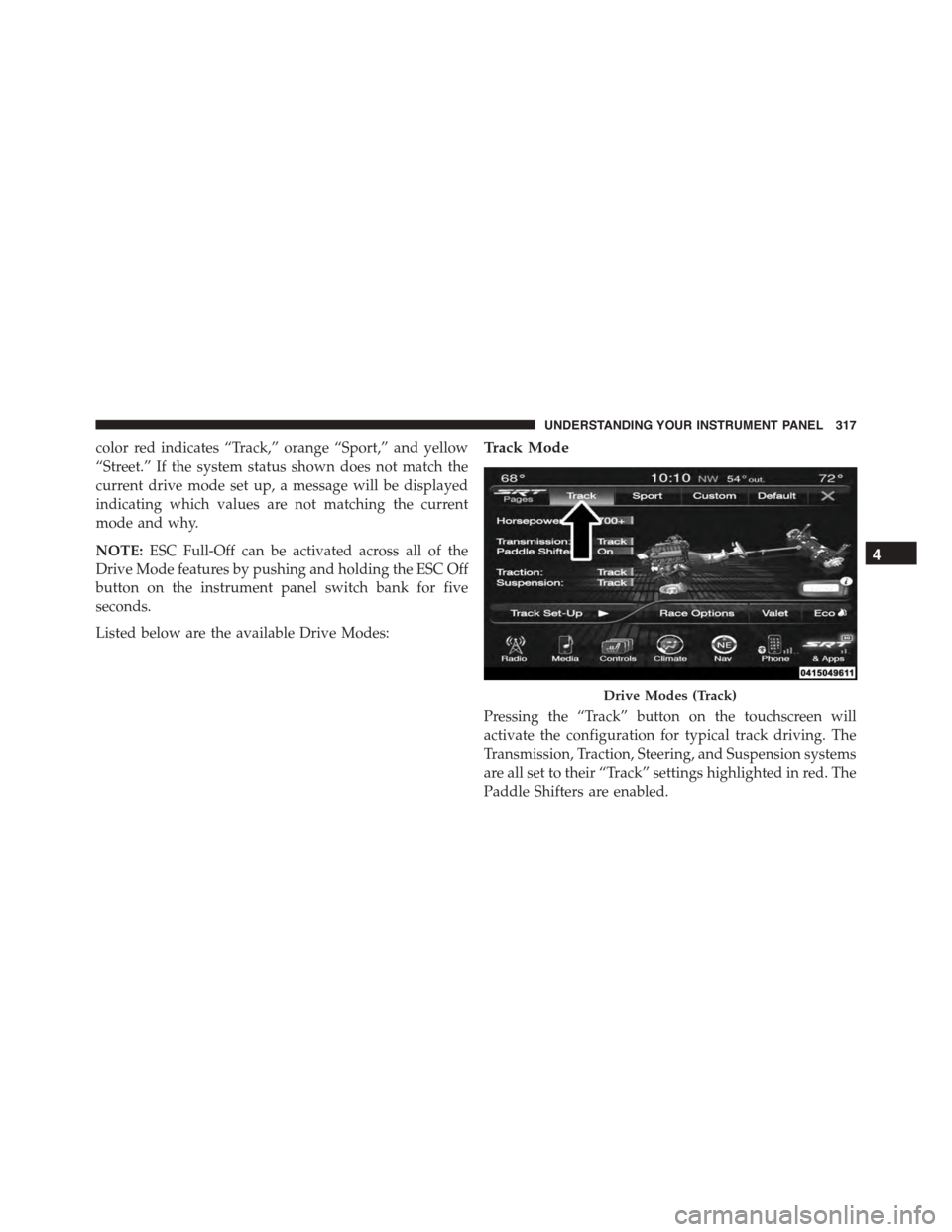
Track Mode
Pressing the “Track” button on the touchscreen will
activate the configuration for typical track driving. The
Transmission, Traction, Steering, and Suspension systems
are all set to their “Track” settings highlighted in red. The
Paddle Shifters are enabled.
Drive Modes (Track)
4
UNDERSTANDING YOUR INSTRUMENT PANEL 317
Page 320 of 595
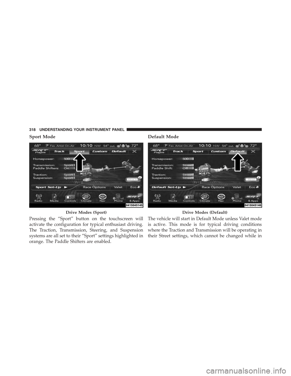
Sport Mode
Pressing the “Sport” button on the touchscreen will
activate the configuration for typical enthusiast driving.
The Traction, Transmission, Steering, and Suspension
systems are all set to their “Sport” settings highlighted in
orange. The Paddle Shifters are enabled.
Default Mode
The vehicle will start in Default Mode unless Valet mode
is active. This mode is for typical driving conditions
where the Traction and Transmission will be operating in
their Street settings, which cannot be changed while in
Drive Modes (Sport)Drive Modes (Default)
318 UNDERSTANDING YOUR INSTRUMENT PANEL
Page 321 of 595
this mode. The Steering and Suspension can be config-
ured in either the “Street,” “Sport,” or “Track” modes and
the Paddle Shifters may be enabled or disabled while in
this mode.
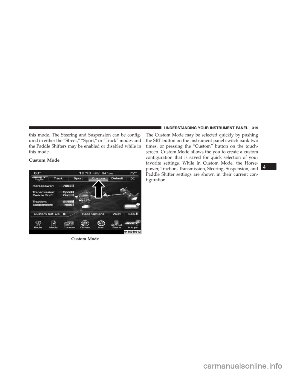
Custom Mode
The Custom Mode may be selected quickly by pushing
the SRT button on the instrument panel switch bank two
times, or pressing the “Custom” button on the touch-
screen. Custom Mode allows the you to create a custom
configuration that is saved for quick selection of your
favorite settings. While in Custom Mode, the Horse-
power, Traction, Transmission, Steering, Suspension, and
Paddle Shifter settings are shown in their current con-
figuration.
Custom Mode
4
UNDERSTANDING YOUR INSTRUMENT PANEL 319
Page 324 of 595
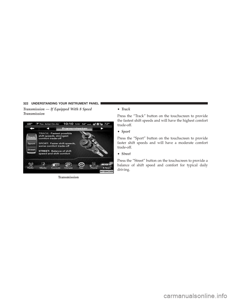
Transmission — If Equipped With 8 Speed
Transmission
•Track
Press the “Track” button on the touchscreen to provide
the fastest shift speeds and will have the highest comfort
trade-off.
•Sport
Press the “Sport” button on the touchscreen to provide
faster shift speeds and will have a moderate comfort
trade-off.
•Street
Press the “Street” button on the touchscreen to provide a
balance of shift speed and comfort for typical daily
driving.
Transmission
322 UNDERSTANDING YOUR INSTRUMENT PANEL
Page 327 of 595
•Sport
Press the “Sport” button on the touchscreen to provide a
firmer suspension stiffness with moderate comfort trade-
off.
•Street
Press the “Street” button on the touchscreen to provide a
balance of suspension stiffness and ride comfort for
typical daily driving.
Steering — If Equipped With 6.4L Engine
•Track
Press the “Track” button on the touchscreen to adjust the
steering effort to the highest level.
•Sport
Press the “Sport” button on the touchscreen to adjust the
steering effort to the higher level.
•Street
Press the “Street#button on the touchscreen to adjust the
steering effort to the lowest level.
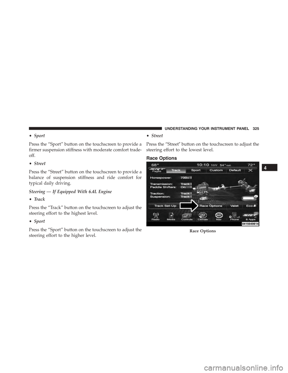
Race Options
Race Options
4
UNDERSTANDING YOUR INSTRUMENT PANEL 325