fuel DODGE DART 2014 PF / 1.G Owner's Manual
[x] Cancel search | Manufacturer: DODGE, Model Year: 2014, Model line: DART, Model: DODGE DART 2014 PF / 1.GPages: 140, PDF Size: 4.57 MB
Page 77 of 140
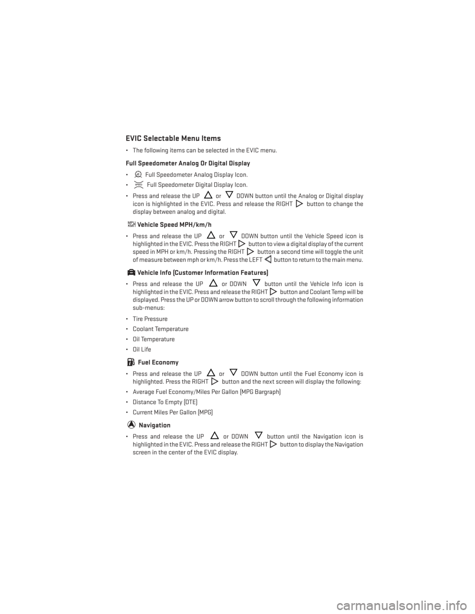
EVIC Selectable Menu Items
• The following items can be selected in the EVIC menu.
Full Speedometer Analog Or Digital Display
•Full Speedometer Analog Display Icon.
•
Full Speedometer Digital Display Icon.
• Press and release the UP
orDOWN button until the Analog or Digital display
icon is highlighted in the EVIC. Press and release the RIGHT
button to change the
display between analog and digital.
Vehicle Speed MPH/km/h
• Press and release the UPorDOWN button until the Vehicle Speed icon is
highlighted in the EVIC. Press the RIGHT
button to view a digital display of the current
speed in MPH or km/h. Pressing the RIGHT
button a second time will toggle the unit
of measure between mph or km/h. Press the LEFT
button to return to the main menu.
Vehicle Info (Customer Information Features)
• Press and release the UPor DOWNbutton until the Vehicle Info icon is
highlighted in the EVIC. Press and release the RIGHT
button and Coolant Temp will be
displayed. Press the UP or DOWN arrow button to scroll through the following information
sub-menus:
• Tire Pressure
• Coolant Temperature
• Oil Temperature
• Oil Life
Fuel Economy
• Press and release the UPorDOWN button until the Fuel Economy icon is
highlighted. Press the RIGHT
button and the next screen will display the following:
• Average Fuel Economy/Miles Per Gallon (MPG Bargraph)
• Distance To Empty (DTE)
• Current Miles Per Gallon (MPG)
Navigation
• Press and release the UPor DOWNbutton until the Navigation icon is
highlighted in the EVIC. Press and release the RIGHT
button to display the Navigation
screen in the center of the EVIC display.
ELECTRONICS
75
Page 85 of 140
ROADSIDE ASSISTANCE
Dial toll-free 1-800-521-2779 for U.S. Residents or 1-800-363-4869 for Canadian Residents.
• Provide your name, vehicle identification number, license plate number, and your loca-tion, including the telephone number from which you are calling.
• Briefly describe the nature of the problem and answer a few simple questions.
•
You will be given the name of the service provider and an estimated time of arrival. If you feel
you are in an “unsafe situation”, please let us know. With your consent, we will contact local
police or safety authorities.
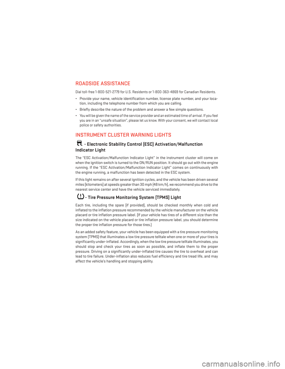
INSTRUMENT CLUSTER WARNING LIGHTS
- Electronic Stability Control (ESC) Activation/Malfunction
Indicator Light
The “ESC Activation/Malfunction Indicator Light” in the instrument cluster will come on
when the ignition switch is turned to the ON/RUN position. It should go out with the engine
running. If the “ESC Activation/Malfunction Indicator Light” comes on continuously with
the engine running, a malfunction has been detected in the ESC system.
If this light remains on after several ignition cycles, and the vehicle has been driven several
miles (kilometers) at speeds greater than 30 mph (48 km/h), we recommend you drive to the
nearest service center and have the vehicle serviced immediately.
- Tire Pressure Monitoring System (TPMS) Light
Each tire, including the spare (if provided), should be checked monthly when cold and
inflated to the inflation pressure recommended by the vehicle manufacturer on the vehicle
placard or tire inflation pressure label. (If your vehicle has tires of a different size than the
size indicated on the vehicle placard or tire inflation pressure label, you should determine
the proper tire inflation pressure for those tires.)
As an added safety feature, your vehicle has been equipped with a tire pressure monitoring
system (TPMS) that illuminates a low tire pressure telltale when one or more of your tires is
significantly under-inflated. Accordingly, when the low tire pressure telltale illuminates, you
should stop and check your tires as soon as possible, and inflate them to the proper
pressure. Driving on a significantly under-inflated tire causes the tire to overheat and can
lead to tire failure. Under-inflation also reduces fuel efficiency and tire tread life, and may
affect the vehicle’s handling and stopping ability.
WHAT TO DO IN EMERGENCIES
83
Page 87 of 140
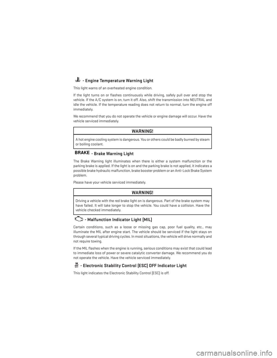
- Engine Temperature Warning Light
This light warns of an overheated engine condition.
If the light turns on or flashes continuously while driving, safely pull over and stop the
vehicle. If the A/C system is on, turn it off. Also, shift the transmission into NEUTRAL and
idle the vehicle. If the temperature reading does not return to normal, turn the engine off
immediately.
We recommend that you do not operate the vehicle or engine damage will occur. Have the
vehicle serviced immediately.
WARNING!
A hot engine cooling system is dangerous. You or others could be badly burned by steam
or boiling coolant.
BRAKE- Brake Warning Light
The Brake Warning light illuminates when there is either a system malfunction or the
parking brake is applied. If the light is on and the parking brake is not applied, it indicates a
possible brake hydraulic malfunction, brake booster problem or an Anti-Lock Brake System
problem.
Please have your vehicle serviced immediately.
WARNING!
Driving a vehicle with the red brake light on is dangerous. Part of the brake system may
have failed. It will take longer to stop the vehicle. You could have a collision. Have the
vehicle checked immediately.
- Malfunction Indicator Light (MIL)
Certain conditions, such as a loose or missing gas cap, poor fuel quality, etc., may
illuminate the MIL after engine start. The vehicle should be serviced if the light stays on
through several typical driving cycles. In most situations, the vehicle will drive normally and
not require towing.
If the MIL flashes when the engine is running, serious conditions may exist that could lead
to immediate loss of power or severe catalytic converter damage. We recommend you do
not operate the vehicle. Have the vehicle serviced immediately.
- Electronic Stability Control (ESC) OFF Indicator Light
This light indicates the Electronic Stability Control (ESC) is off.
WHAT TO DO IN EMERGENCIES
85
Page 88 of 140
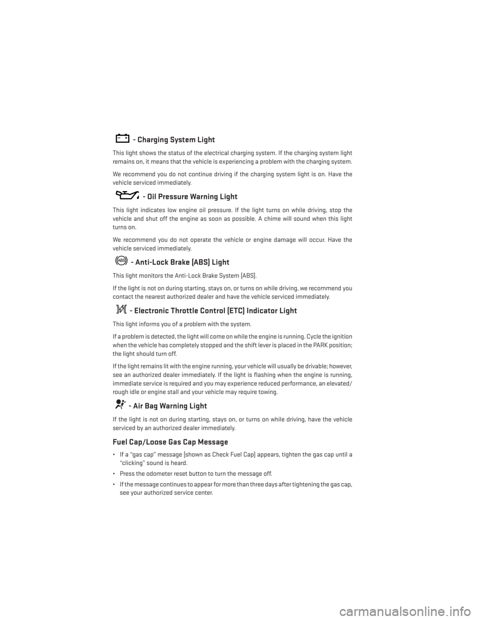
- Charging System Light
This light shows the status of the electrical charging system. If the charging system light
remains on, it means that the vehicle is experiencing a problem with the charging system.
We recommend you do not continue driving if the charging system light is on. Have the
vehicle serviced immediately.
- Oil Pressure Warning Light
This light indicates low engine oil pressure. If the light turns on while driving, stop the
vehicle and shut off the engine as soon as possible. A chime will sound when this light
turns on.
We recommend you do not operate the vehicle or engine damage will occur. Have the
vehicle serviced immediately.
- Anti-Lock Brake (ABS) Light
This light monitors the Anti-Lock Brake System (ABS).
If the light is not on during starting, stays on, or turns on while driving, we recommend you
contact the nearest authorized dealer and have the vehicle serviced immediately.
- Electronic Throttle Control (ETC) Indicator Light
This light informs you of a problem with the system.
If a problem is detected, the light will come on while the engine is running. Cycle the ignition
when the vehicle has completely stopped and the shift lever is placed in the PARK position;
the light should turn off.
If the light remains lit with the engine running, your vehicle will usually be drivable; however,
see an authorized dealer immediately. If the light is flashing when the engine is running,
immediate service is required and you may experience reduced performance, an elevated/
rough idle or engine stall and your vehicle may require towing.
- Air Bag Warning Light
If the light is not on during starting, stays on, or turns on while driving, have the vehicle
serviced by an authorized dealer immediately.
Fuel Cap/Loose Gas Cap Message
• If a “gas cap” message (shown as Check Fuel Cap) appears, tighten the gas cap until a“clicking” sound is heard.
• Press the odometer reset button to turn the message off.
• If the message continues to appear for more than three days after tightening the gas cap, see your authorized service center.
WHAT TO DO IN EMERGENCIES
86
Page 103 of 140
JUMP-STARTING
• If your vehicle has a discharged battery itcan be jump-started using a set of jumper
cables and a battery in another vehicle or
by using a portable battery booster pack.
• Jump-starting can be dangerous if done improperly so please follow the proce-
dures in this section carefully.
NOTE:
When using a portable battery booster pack
follow the manufacturer’s operating instruc-
tions and precautions.
Preparations For Jump-Start
• The battery in your vehicle is located in the front of the engine compartment,
behind the left headlight assembly.
NOTE:
The positive battery post is covered with a protective cap. Lift up on the cap to gain access
to the positive battery post.
• Set the parking brake, shift the automatic transmission into PARK (manual transmission in NEUTRAL) and turn the ignition to LOCK.
• Turn off the heater, radio, and all unnecessary electrical accessories.
• If using another vehicle to jump-start the battery, park the vehicle within the jumper cables reach, set the parking brake and make sure the ignition is OFF.
Jump-Starting Procedure
1. Connect the positive (+)end of the jumper cable to the positive (+)post of the vehicle with
the discharged battery.
2. Connect the opposite end of the positive (+)jumper cable to the positive (+)post of the
booster battery.
3. Connect the negative (-)end of the jumper cable to the negative (-)post of the booster
battery.
4. Connect the opposite end of the negative (-)jumper cable to a good engine ground
(exposed metal part of the discharged vehicle’s engine) away from the battery and the
fuel injection system.
5. Start the engine in the vehicle that has the booster battery, let the engine idle a few minutes, and then start the engine in the vehicle with the discharged battery.
WHAT TO DO IN EMERGENCIES
101
Page 109 of 140
FUEL DOOR RELEASE
• The fuel door release button is located onthe instrument panel below the headlight
switch.
• Push the button once and release to open the fuel door.
Fuel Door Emergency Release
• If you are unable to open the fuel fillerdoor, use the manual fuel filler door re-
lease.
1. Open the trunk.
2. Locate the release cable access door cut out on the right side of the trunk
trim.
3. Insert finger into half circle opening and pull flap open to access the
cable.
4. Pull the release cable.
MAINTAINING YOUR VEHICLE
107
Page 113 of 140
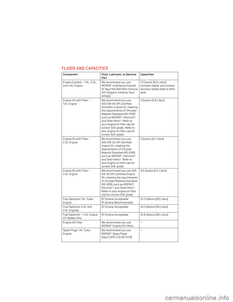
FLUIDS AND CAPACITIES
ComponentFluid, Lubricant, or Genuine
Part Capacities
Engine Coolant – 1.4L, 2.0L,
and 2.4L Engine We recommend you use
MOPAR® Antifreeze/Coolant
10 Year/150,000 Mile Formula
OAT (Organic Additive Tech-
nology). 7.2 Quarts (6.8 Liters)
Includes heater and coolant
recovery bottle filled to MAX
level.
Engine Oil with Filter –
1.4L Engine We recommend you use
SAE 5W-40 API Certified
Synthetic Engine Oil, meeting
the requirements of Chrysler
Material Standard MS-12991
such as MOPAR®, Pennzoil®,
and Shell Helix®. Refer to
your engine oil filler cap for
correct SAE grade. Refer to
your engine oil filler cap for
correct SAE grade. 4 Quarts (3.8 Liters)
Engine Oil with Filter –
2.0L Engine We recommend you use
SAE 0W-20 API Certified
Engine Oil, meeting the
requirements of Chrysler
Material Standard MS-6395
such as MOPAR®, Pennzoil®,
and Shell Helix®. Refer to
your engine oil filler cap for
correct SAE grade. 5 Quarts (4.7 Liters)
Engine Oil with Filter –
2.4L Engine We recommend you use SAE
0W-20 API Certified Engine
Oil, meeting the requirements
of Chrysler Material Standard
MS-6395 such as MOPAR®,
Pennzoil®, and Shell Helix®.
Refer to your engine oil filler
cap for correct SAE grade. 5.5 Quarts (5.2 Liters)
Fuel Selection 1.4L Turbo
Engine 87 Octane Acceptable
91 Octane Recommended 13.2 Gallons (50 Liters)
Fuel Selection 2.0L and
2.4L Engines 87 Octane Acceptable 14.2 Gallons (54 Liters)
Fuel Selection – 2.4L Engine
GT Models Only 87 Octane Acceptable 15.8 Gallons (60 Liters)
Engine Oil Filter We recommend you use
MOPAR® Engine Oil Filters. —
Spark Plugs 1.4L Turbo
Engine We recommend you use
MOPAR® Spark Plugs
(Gap 0.025 in [0.65 mm]) —
MAINTAINING YOUR VEHICLE
111
Page 115 of 140
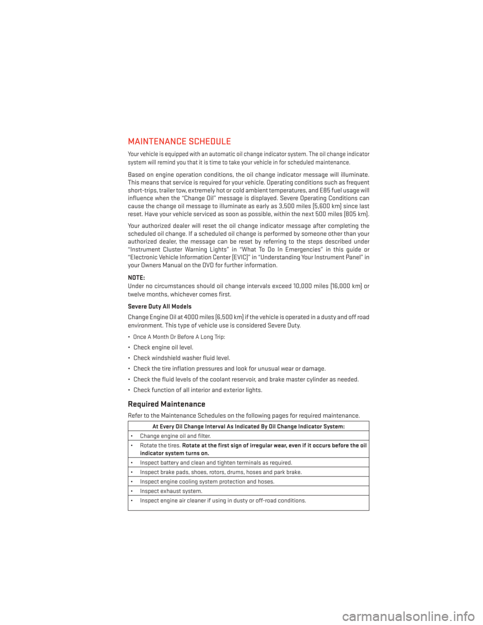
MAINTENANCE SCHEDULE
Your vehicle is equipped with an automatic oil change indicator system. The oil change indicator
system will remind you that it is time to take your vehicle in for scheduled maintenance.
Based on engine operation conditions, the oil change indicator message will illuminate.
This means that service is required for your vehicle. Operating conditions such as frequent
short-trips, trailer tow, extremely hot or cold ambient temperatures, and E85 fuel usage will
influence when the “Change Oil” message is displayed. Severe Operating Conditions can
cause the change oil message to illuminate as early as 3,500 miles (5,600 km) since last
reset. Have your vehicle serviced as soon as possible, within the next 500 miles (805 km).
Your authorized dealer will reset the oil change indicator message after completing the
scheduled oil change. If a scheduled oil change is performed by someone other than your
authorized dealer, the message can be reset by referring to the steps described under
“Instrument Cluster Warning Lights” in “What To Do In Emergencies” in this guide or
“Electronic Vehicle Information Center (EVIC)” in “Understanding Your Instrument Panel” in
your Owners Manual on the DVD for further information.
NOTE:
Under no circumstances should oil change intervals exceed 10,000 miles (16,000 km) or
twelve months, whichever comes first.
Severe Duty All Models
Change Engine Oil at 4000 miles (6,500 km) if the vehicle is operated in a dusty and off road
environment. This type of vehicle use is considered Severe Duty.
• Once A Month Or Before A Long Trip:
• Check engine oil level.
• Check windshield washer fluid level.
• Check the tire inflation pressures and look for unusual wear or damage.
• Check the fluid levels of the coolant reservoir, and brake master cylinder as needed.
• Check function of all interior and exterior lights.
Required Maintenance
Refer to the Maintenance Schedules on the following pages for required maintenance.
At Every Oil Change Interval As Indicated By Oil Change Indicator System:
• Change engine oil and filter.
• Rotate the tires. Rotate at the first sign of irregular wear, even if it occurs before the oil
indicator system turns on.
• Inspect battery and clean and tighten terminals as required.
• Inspect brake pads, shoes, rotors, drums, hoses and park brake.
• Inspect engine cooling system protection and hoses.
• Inspect exhaust system.
• Inspect engine air cleaner if using in dusty or off-road conditions.
MAINTAINING YOUR VEHICLE
113
Page 119 of 140
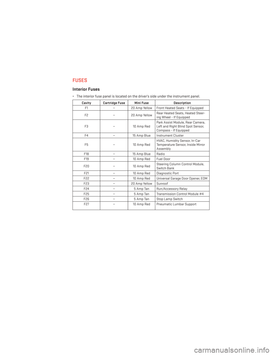
FUSES
Interior Fuses
• The interior fuse panel is located on the driver's side under the instrument panel.
Cavity Cartridge Fuse Mini FuseDescription
F1 — 20 Amp Yellow Front Heated Seats - If Equipped
F2 — 20 Amp Yellow Rear Heated Seats, Heated Steer-
ing Wheel - If Equipped
F3 — 10 Amp Red Park Assist Module, Rear Camera,
Left and Right Blind Spot Sensor,
Compass - If Equipped
F4 — 15 Amp Blue Instrument Cluster
F5 — 10 Amp Red HVAC, Humidity Sensor, In-Car
Temperature Sensor, Inside Mirror
Assembly
F18 — 15 Amp Blue Radio
F19 — 10 Amp Red Fuel Door
F20 — 10 Amp Red Steering Column Control Module,
Switch Bank
F21 — 10 Amp Red Diagnostic Port
F22 — 10 Amp Red Universal Garage Door Opener, EOM
F23 — 20 Amp Yellow Sunroof
F24 —5 Amp Tan Run/Accessory Relay
F25 —5 Amp Tan Transmission Control Module #4
F26 —5 Amp Tan Stop Lamp Switch
F27 — 10 Amp Red Pneumatic Lumbar Support
MAINTAINING YOUR VEHICLE
117
Page 120 of 140
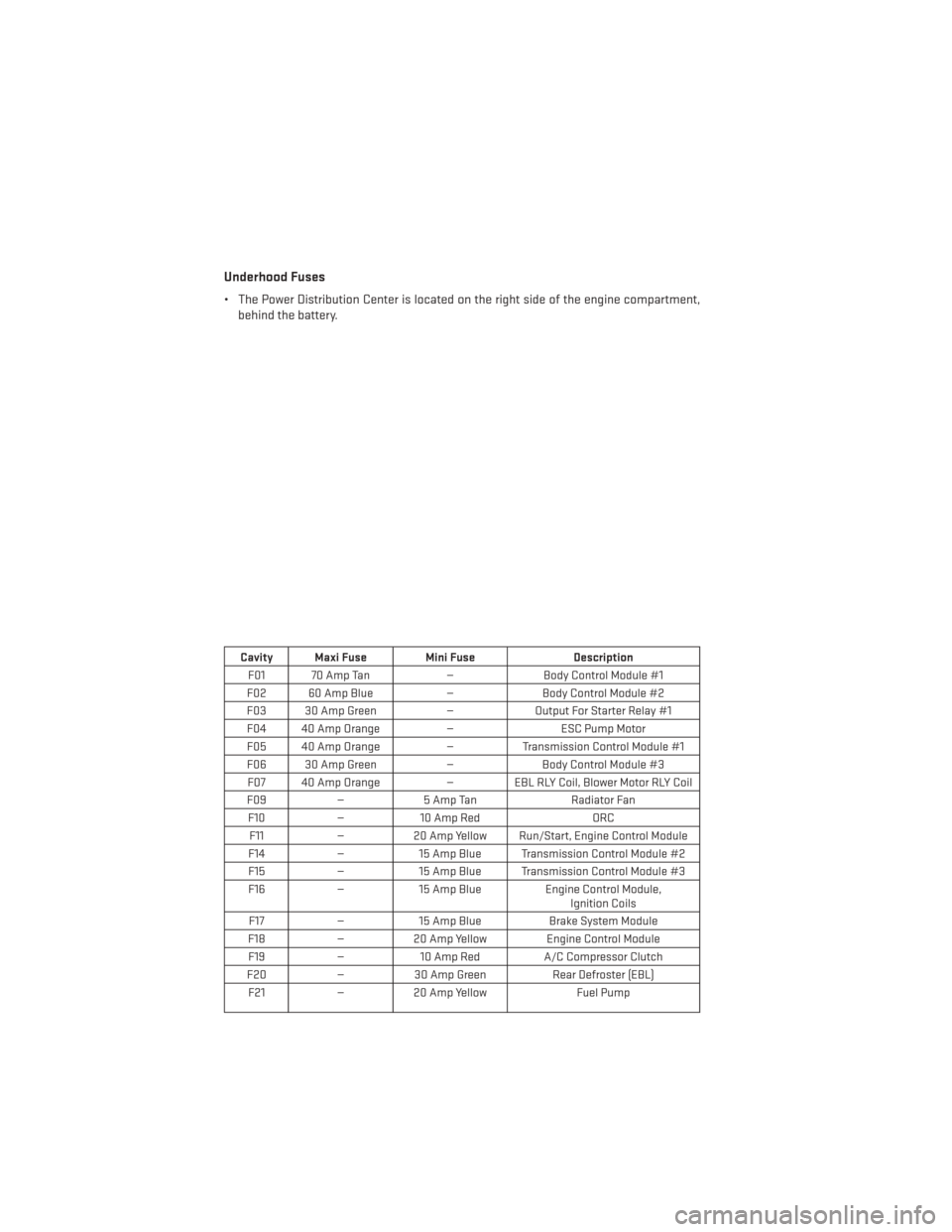
Underhood Fuses
• The Power Distribution Center is located on the right side of the engine compartment,behind the battery.
Cavity Maxi Fuse Mini Fuse Description
F01 70 Amp Tan —Body Control Module #1
F02 60 Amp Blue —Body Control Module #2
F03 30 Amp Green —Output For Starter Relay #1
F04 40 Amp Orange —ESC Pump Motor
F05 40 Amp Orange —Transmission Control Module #1
F06 30 Amp Green —Body Control Module #3
F07 40 Amp Orange — EBL RLY Coil, Blower Motor RLY Coil
F09 —5 Amp Tan Radiator Fan
F10 —10 Amp Red ORC
F11 —20 Amp Yellow Run/Start, Engine Control Module
F14 —15 Amp Blue Transmission Control Module #2
F15 —15 Amp Blue Transmission Control Module #3
F16 —15 Amp Blue Engine Control Module,
Ignition Coils
F17 —15 Amp Blue Brake System Module
F18 —20 Amp Yellow Engine Control Module
F19 —10 Amp Red A/C Compressor Clutch
F20 —30 Amp Green Rear Defroster (EBL)
F21 —20 Amp Yellow Fuel Pump
MAINTAINING YOUR VEHICLE
118