steering wheel DODGE DART 2015 PF / 1.G User Guide
[x] Cancel search | Manufacturer: DODGE, Model Year: 2015, Model line: DART, Model: DODGE DART 2015 PF / 1.GPages: 164, PDF Size: 25.19 MB
Page 3 of 164
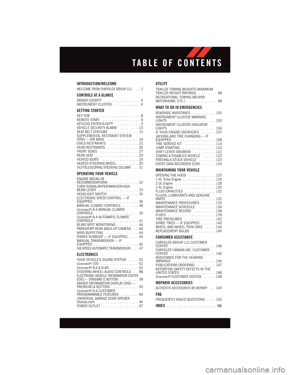
INTRODUCTION/WELCOME
WELCOME FROM CHRYSLER GROUP LLC..2
CONTROLS AT A GLANCE
DRIVER COCKPIT...............4INSTRUMENT CLUSTER...........6
GETTING STARTED
KEY FOB . . . . . . . . . . . . . . . . . . . . 8REMOTE START . . . . . . . . . . . . . . . . 9KEYLESS ENTER-N-GO™..........9VEHICLE SECURITY ALARM........13SEAT BELT SYSTEMS............15SUPPLEMENTAL RESTRAINT SYSTEM(SRS) — AIR BAGS.............16CHILD RESTRAINTS............22HEAD RESTRAINTS.............26FRONT SEATS................27REAR SEAT..................29HEATED SEATS . . . . . . . . . . . . . . . 29HEATED STEERING WHEEL........30TILT/TELESCOPING STEERING COLUMN..31
OPERATING YOUR VEHICLE
ENGINE BREAK-INRECOMMENDATIONS............32TURN SIGNAL/WIPER/WASHER/HIGHBEAM LEVER.................33HEADLIGHT SWITCH............35ELECTRONIC SPEED CONTROL — IFEQUIPPED...................36MANUAL CLIMATE CONTROLS.......38Uconnect®8.4 MANUAL CLIMATECONTROLS..................39Uconnect®8.4 AUTOMATIC CLIMATECONTROLS..................41BLIND SPOT MONITORING.........44PA R K V I E W®REAR BACK-UP CAMERA . . 44WIND BUFFETING..............44POWER SUNROOF — IF EQUIPPED....45MANUAL TRANSMISSION — IFEQUIPPED...................46SIX-SPEED AUTOMATIC TRANSMISSION . . . 47
ELECTRONICS
YOUR VEHICLE'S SOUND SYSTEM....50Uconnect®200 . . . . . . . . . . . . . . . . 52Uconnect®8.4 & 8.4N............62STEERING WHEEL AUDIO CONTROLS . . 88ELECTRONIC VEHICLE INFORMATIONCENTER(EVIC) — STANDARD (2 BUTTON) . . . . . . . . 89DRIVER INFORMATION DISPLAY (DID) —PREMIUM (4 BUTTON)...........90Uconnect®8.4 CUSTOMERPROGRAMMABLE FEATURES.......94UNIVERSAL GARAGE DOOR OPENER(HomeLink®).................94POWER OUTLET...............97
UTILITY
TRAILER TOWING WEIGHTS (MAXIMUMTRAILER WEIGHT RATINGS)........98RECREATIONAL TOWING (BEHINDMOTORHOME, ETC.)............98
WHAT TO DO IN EMERGENCIES
ROADSIDE ASSISTANCE..........100INSTRUMENT CLUSTER WARNINGLIGHTS...................100INSTRUMENT CLUSTER INDICATORLIGHTS...................106IF YOUR ENGINE OVERHEATS......107JACKING AND TIRE CHANGING — IFEQUIPPED..................108TIRE SERVICE KIT.............114JUMP-STARTING..............120SHIFT LEVER OVERRIDE.........122TOWING A DISABLED VEHICLE.....123FREEING A STUCK VEHICLE.......123EVENT DATA RECORDER (EDR).....124
MAINTAINING YOUR VEHICLE
OPENING THE HOOD...........1251.4L Turbo Engine..............1262.0L Engine.................1282.4L Engine.................130FLUID CAPACITIES.............132FLUIDS, LUBRICANTS AND GENUINEPA RT S . . . . . . . . . . . . . . . . . . . . 1 3 2MAINTENANCE PROCEDURES......133MAINTENANCE SCHEDULE.......134MAINTENANCE RECORD.........138FUSES....................139TIRE PRESSURES.............142SPARE TIRES — IF EQUIPPED......143WHEEL AND WHEEL TRIM CARE....144REPLACEMENT BULBS..........145
CONSUMER ASSISTANCE
CHRYSLER GROUP LLC CUSTOMERCENTER...................146CHRYSLER CANADA INC. CUSTOMERCENTER...................146ASSISTANCE FOR THE HEARINGIMPAIRED..................146PUBLICATIONS ORDERING........147REPORTING SAFETY DEFECTS IN THEUNITED STATES..............148Uconnect®CUSTOMER CENTER.....148
MOPAR® ACCESSORIES
AUTHENTIC ACCESSORIES BY MOPAR®..149
FAQ
FREQUENTLY ASKED QUESTIONS....150
INDEX.....................152
TABLE OF CONTENTS
Page 18 of 164
SUPPLEMENTAL RESTRAINT SYSTEM (SRS) — AIR BAGS
Air Bag System Components
Yo u r v e h i c l e m a y b e e q u i p p e d w i t h t h e f o l l o w i n g a i r b a g s y s t e m c o m p o n e n t s :
•OccupantRestraintController(ORC)
•AirBagWarningLight
•SteeringWheelandColumn
•InstrumentPanel
•KneeImpactBolsters
•AdvancedFrontAirBags
•SupplementalSideAirBags
•SupplementalKneeAirBags
•FrontandSideImpactSensors
•SeatBeltPretenioners
•SeatBeltBuckleSwitch
•SeatTrackPositionSensors
•OccupantClassificationSystem
Advanced Front Air Bags
•ThisvehiclehasAdvancedFrontAirBagsforboththedriverandfrontpassengerasa
supplement to the seat belt restraint systems. The Advanced Front Air Bags will not
deploy in every type of collision.
•AdvancedFrontAirBagsaredesignedtoprovideadditionalprotectionbysupplement-
ing the seat belts. Advanced Front Air Bags are not expected to reduce the risk of injury
in rear, side, or rollover collisions.
•TheAdvancedFrontAirBagswillnotdeployinallfrontalcollisions,includingsome
that may produce substantial vehicle damage — for example, some pole collisions,
truck underrides, and angle offset collisions.
•Ontheotherhand,dependingonthetypeandlocationofimpact,AdvancedFrontAir
Bags may deploy in crashes with little vehicle front-end damage but that produce a
severe initial deceleration.
•Becauseairbagsensorsmeasurevehicledecelerationovertime,vehiclespeedand
damage by themselves are not good indicators of whether or not an air bag should have
deployed.
•Seatbeltsarenecessaryforyourprotectioninallcollisions,andalsoareneededtohelp
keep you in position, away from an inflating air bag.
•Theairbagsmustbereadytoinflateforyourprotectioninacollision.TheOccupant
Restraint Controller (ORC) monitors the internal circuits and interconnecting wiring
associated with air bag system electrical components.
GETTING STARTED
16
Page 23 of 164
•AtnotimeshouldanySupplementalRestraintSystem(SRS)componentorSRS
related component or fastener be modified or replaced with any part except those which
are approved by Chrysler Group LLC.
Supplemental Knee Air Bags
This vehicle is equipped with a Supplemental Driver Knee Air Bag mounted in the
instrument panel below the steering column and a Supplemental Passenger Knee Air Bag
mounted in the instrument panel below the glove compartment. The Supplemental Knee
Air Bags provide enhanced protection during a frontal impact by working together with the
seat belts, pretensioners, and Advanced Front Air Bags.
WARNING!
•Relyingontheairbagsalonecouldleadtomoresevereinjuriesinacollision.The
air bags work with your seat belt to restrain you properly. In some collisions, the air
bags won't deploy at all. Always wear your seat belts even though you have air bags.
•BeingtooclosetothesteeringwheelorinstrumentpanelduringAdvancedFrontAir
Bag deployment could cause serious injury, including death. Air bags need room to
inflate. Sit back, comfortably extending your arms to reach the steering wheel or
instrument panel.
•Noobjectsshouldbeplacedoverorneartheairbagontheinstrumentpanelor
steering wheel because any such objects could cause harm if the vehicle is in a
collision severe enough to cause the air bag to inflate.
Supplemental Side Air Bags
•ThisvehicleisequippedwithSupplementalSeat-MountedSideAirBags(SABs)
located in the outboard side of the front and rear (in vehicles equipped with outboard
rear seat SABs) seats. The SABs are marked with a SRS AIRBAG label sewn into the
outboard side of the seats.
•ThisvehicleisequippedwithSupplementalSideAirBagInflatableCurtains(SABICs)
located above the side windows. The trim covering the SABICs is labeled SRS AIRBAG.
The SABICs may help reduce the risk of partial or complete ejection of vehicle
occupants through side windows in certain side impact events.
•TheSABICsandSABs(“SideAirBags”)aredesignedtoactivateincertainside
impacts. The Occupant Restraint Controller (“ORC”) determines whether the deploy-
ment of the Side Air Bags in a particular impact event is appropriate, based on the
severity and type of collision. Vehicle damage by itself is not a good indicator of whether
or not Side Air Bags should have deployed.
GETTING STARTED
21
Page 32 of 164
NOTE:
On models that are equipped with remote start, this feature can be programmed to come
on during a remote start through the Uconnect®system. Refer to “Uconnect®Settings”
in “Understanding Your Instrument Panel” in the Owner's Manual on the DVD.
WARNING!
•Personswhoareunabletofeelpaintotheskinbecauseofadvancedage,chronic
illness, diabetes, spinal cord injury, medication, alcohol use, exhaustion or other
physical conditions must exercise care when using the seat heater. It may cause
burns even at low temperatures, especially if used for long periods of time.
•Donotplaceanythingontheseatthatinsulatesagainstheat,suchasablanketor
cushion. This may cause the seat heater to overheat. Sitting in a seat that has been
overheated could cause serious burns due to the increased surface temperature of
the seat.
HEATED STEERING WHEEL
The steering wheel contains a heating element that heats the steering wheel to one
temperature setting.
The heated steering wheel control button is located within the Uconnect®system. You can
gain access to the control buttons through the climate screen or the controls screen.
•Presstheheatedsteeringwheelbuttononce to turn the heating element ON.
•Presstheheatedsteeringwheelbuttonasecondtimetoturntheheatingelement
OFF.
Once the heated steering wheel has been turned on, it will operate for up to 80 minutes
before automatically shutting off. The heated steering wheel can shut off early or may not
turn on when the steering wheel is already warm.
NOTE:
Vehicle Equipped With Remote Start
On models that are equipped with remote start, this feature can be programmed to come
on during a remote start through the Uconnect®system. Refer to “Uconnect®Settings”
in “Understanding Your Instrument Panel” in the Owner's Manual on the DVD.
WARNING!
•Personswhoareunabletofeelpaintotheskinbecauseofadvancedage,chronic
illness, diabetes, spinal cord injury, medication, alcohol use, exhaustion, or other
physical conditions must exercise care when using the steering wheel heater. It may
cause burns even at low temperatures, especially if used for long periods.
•Donotplaceanythingonthesteeringwheelthatinsulatesagainstheat,suchasa
blanket or steering wheel covers of any type and material. This may cause the
steering wheel heater to overheat.
GETTING STARTED
30
Page 33 of 164
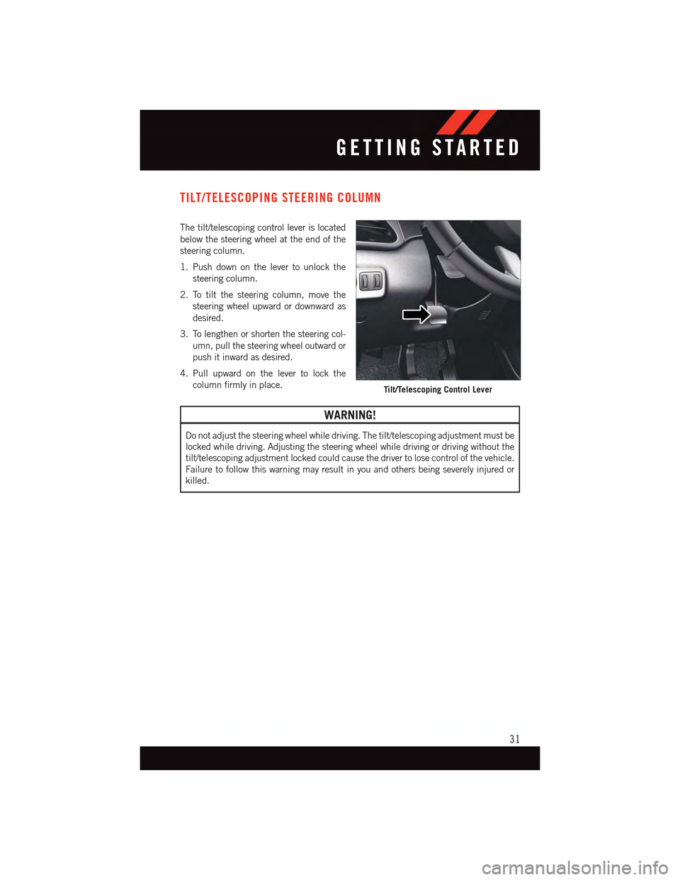
TILT/TELESCOPING STEERING COLUMN
The tilt/telescoping control lever is located
below the steering wheel at the end of the
steering column.
1. Push down on the lever to unlock the
steering column.
2. To tilt the steering column, move the
steering wheel upward or downward as
desired.
3. To lengthen or shorten the steering col-
umn, pull the steering wheel outward or
push it inward as desired.
4. Pull upward on the lever to lock the
column firmly in place.
WARNING!
Do not adjust the steering wheel while driving. The tilt/telescoping adjustment must be
locked while driving. Adjusting the steering wheel while driving or driving without the
tilt/telescoping adjustment locked could cause the driver to lose control of the vehicle.
Failure to follow this warning may result in you and others being severely injured or
killed.
Tilt/Telescoping Control Lever
GETTING STARTED
31
Page 37 of 164
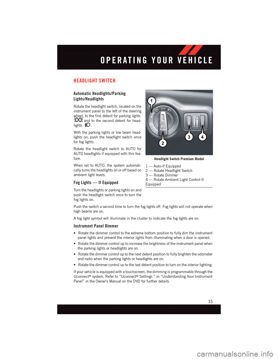
HEADLIGHT SWITCH
Automatic Headlights/Parking
Lights/Headlights
Rotate the headlight switch, located on the
instrument panel to the left of the steering
wheel, to the first detent for parking lights
and to the second detent for head-
lights.
With the parking lights or low beam head-
lights on, push the headlight switch once
for fog lights.
Rotate the headlight switch to AUTO for
AUTO headlights if equipped with this fea-
ture.
When set to AUTO, the system automati-
cally turns the headlights on or off based on
ambient light levels.
Fog Lights — If Equipped
Tu r n t h e h e a d l i g h t s o r p a r k i n g l i g h t s o n a n d
push the headlight switch once to turn the
fog lights on.
Push the switch a second time to turn the fog lights off. Fog lights will not operate when
high beams are on.
Afoglightsymbolwillilluminateintheclustertoindicatethefoglightsareon.
Instrument Panel Dimmer
•Rotatethedimmercontroltotheextremebottompositiontofullydimtheinstrument
panel lights and prevent the interior lights from illuminating when a door is opened.
•Rotatethedimmercontroluptoincreasethebrightnessoftheinstrumentpanelwhen
the parking lights or headlights are on.
•Rotatethedimmercontroluptothenextdetentpositiontofullybrightentheodometer
and radio when the parking lights or headlights are on.
•Rotatethedimmercontroluptothelastdetentpositiontoturnontheinteriorlighting.
If your vehicle is equipped with a touchscreen, the dimming is programmable through the
Uconnect®system. Refer to “Uconnect®Settings ” in “Understanding Your Instrument
Panel” in the Owner's Manual on the DVD for further details.
Headlight Switch Premium Model
1—Auto-IfEquipped2—RotateHeadlightSwitch3—RotateDimmer4—RotateAmbientLightControl-IfEquipped
OPERATING YOUR VEHICLE
35
Page 38 of 164
ELECTRONIC SPEED CONTROL — IF EQUIPPED
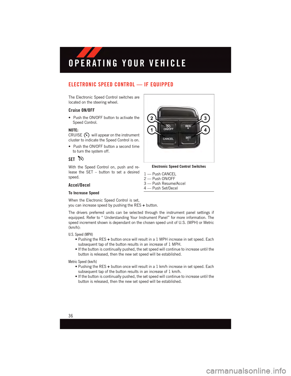
The Electronic Speed Control switches are
located on the steering wheel.
Cruise ON/OFF
•PushtheON/OFFbuttontoactivatethe
Speed Control.
NOTE:
CRUISEwill appear on the instrument
cluster to indicate the Speed Control is on.
•PushtheON/OFFbuttonasecondtime
to turn the system off.
SET
With the Speed Control on, push and re-
lease the SET – button to set a desired
speed.
Accel/Decel
To Increase Speed
When the Electronic Speed Control is set,
you can increase speed by pushing the RES+button.
The drivers preferred units can be selected through the instrument panel settings if
equipped. Refer to “ Understanding Your Instrument Panel” for more information. The
speed increment shown is dependant on the chosen speed unit of U.S. (MPH) or Metric
(km/h):
U.S. Speed (MPH)
•PushingtheRES+button once will result in a 1 MPH increase in set speed. Each
subsequent tap of the button results in an increase of 1 MPH.
•Ifthebuttoniscontinuallypushed,thesetspeedwillcontinuetoincreaseuntilthe
button is released, then the new set speed will be established.
Metric Speed (km/h)
•PushingtheRES+button once will result in a 1 km/h increase in set speed. Each
subsequent tap of the button results in an increase of 1 km/h.
•Ifthebuttoniscontinuallypushed,thesetspeedwillcontinuetoincreaseuntilthe
button is released, then the new set speed will be established.
Electronic Speed Control Switches
1—PushCANCEL2—PushON/OFF3—PushResume/Accel4—PushSet/Decel
OPERATING YOUR VEHICLE
36
Page 52 of 164
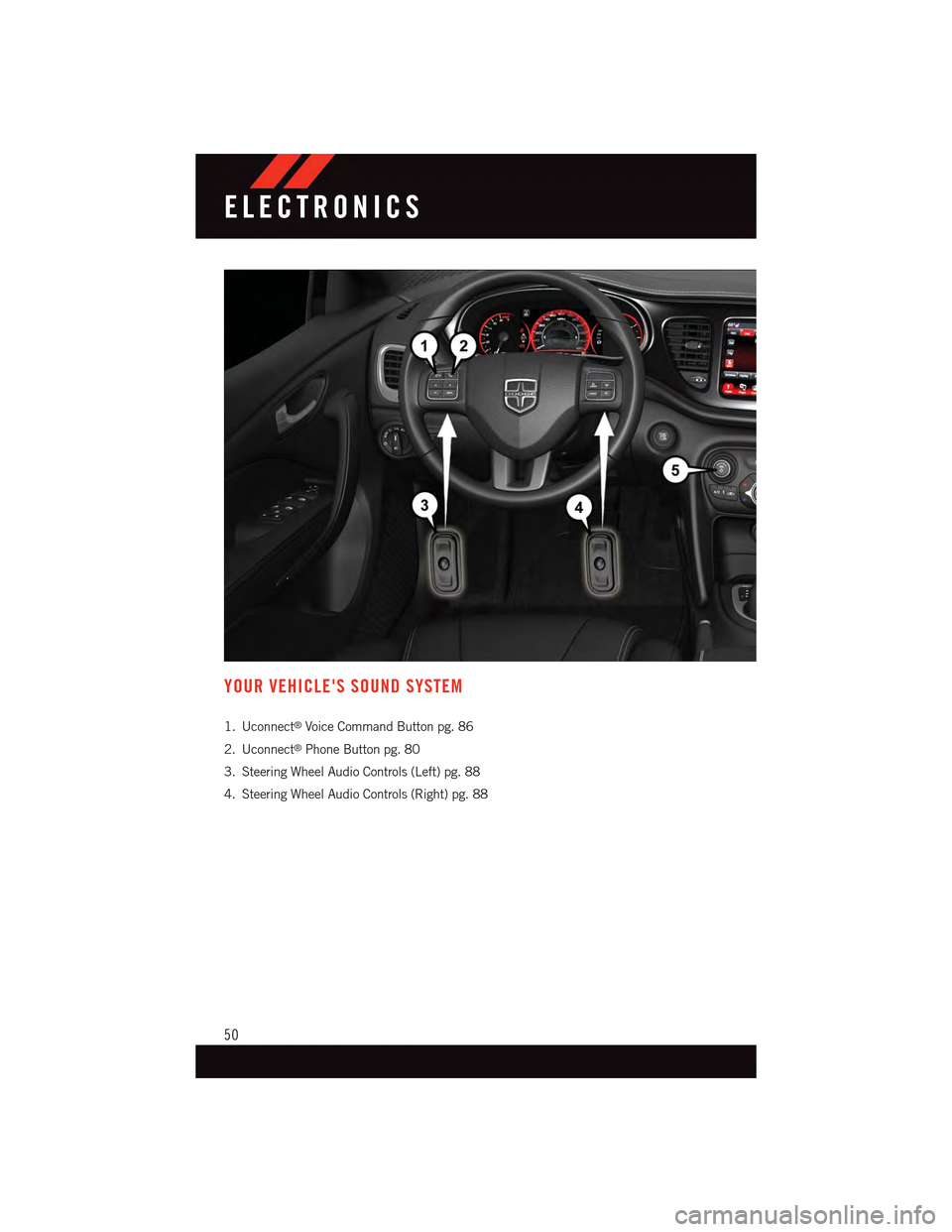
YOUR VEHICLE'S SOUND SYSTEM
1. Uconnect®Voice Command Button pg. 86
2. Uconnect®Phone Button pg. 80
3. Steering Wheel Audio Controls (Left) pg. 88
4. Steering Wheel Audio Controls (Right) pg. 88
ELECTRONICS
50
Page 54 of 164
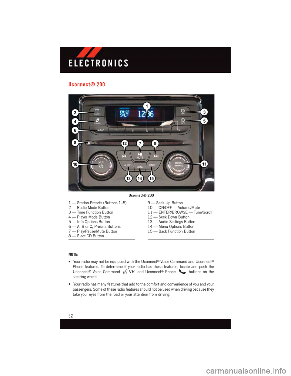
Uconnect® 200
NOTE:
•YourradiomaynotbeequippedwiththeUconnect®Voice Command and Uconnect®
Phone features. To determine if your radio has these features, locate and push the
Uconnect®Voice Commandand Uconnect®Phonebuttons on the
steering wheel.
•Yourradiohasmanyfeaturesthataddtothecomfortandconvenienceofyouandyour
passengers. Some of these radio features should not be used when driving because they
take your eyes from the road or your attention from driving.
Uconnect® 200
1—StationPresets(Buttons1–5)2—RadioModeButton3—TimeFunctionButton4—PlayerModeButton5—InfoOptionsButton6—A,BorC,PresetsButtons7—Play/Pause/MuteButton8—EjectCDButton
9—SeekUpButton10 — ON/OFF — Volume/Mute11 — ENTER/BROWSE — Tune/Scroll12 — Seek Down Button13 — Audio Settings Button14 — Menu Options Button15 — Back Function Button
ELECTRONICS
52
Page 58 of 164
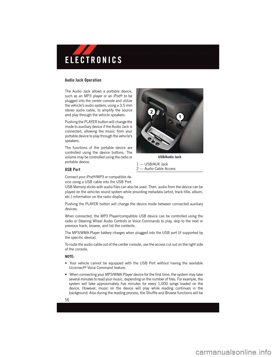
Audio Jack Operation
The Audio Jack allows a portable device,
such as an MP3 player or an iPod®to be
plugged into the center console and utilize
the vehicle’s audio system, using a 3.5 mm
stereo audio cable, to amplify the source
and play through the vehicle speakers.
Pushing the PLAYER button will change the
mode to auxiliary device if the Audio Jack is
connected, allowing the music from your
portable device to play through the vehicle's
speakers.
The functions of the portable device are
controlled using the device buttons. The
volume may be controlled using the radio or
portable device.
USB Port
Connect your iPod®/MP3 or compatible de-
vice using a USB cable into the USB Port.
USB Memory sticks with audio files can also be used. Then, audio from the device can be
played on the vehicles sound system while providing metadata (artist, track title, album,
etc.) information on the radio display.
Pushing the PLAYER button will change the device mode between connected auxiliary
devices.
When connected, the MP3 Player/compatible USB device can be controlled using the
radio or Steering Wheel Audio Controls or Voice Commands to play, skip to the next or
previous track, browse, and list the contents.
The MP3/WMA Player battery charges when plugged into the USB port (if supported by
the specific device).
To r o u t e t h e a u d i o c a b l e o u t o f t h e c e n t e r c o n s o l e , u s e t h e a c c e s s c u t o u t o n t h e r i g h t s i d e
of the console.
NOTE:
•YourvehiclecannotbeequippedwiththeUSBPortwithouthavingtheavailable
Uconnect®Voice Command feature.
•WhenconnectingyourMP3/WMAPlayerdeviceforthefirsttime,thesystemmaytake
several minutes to read your music, depending on the number of files. For example, the
system will take approximately five minutes for every 1,000 songs loaded on the
device. However, music on the device will play while reading continues in the
background. Also during the reading process, the Shuffle and Browse functions will be
USB/Audio Jack
1—USB/AUXJack2—AudioCableAccess
ELECTRONICS
56