brake light DODGE DURANGO 2014 3.G User Guide
[x] Cancel search | Manufacturer: DODGE, Model Year: 2014, Model line: DURANGO, Model: DODGE DURANGO 2014 3.GPages: 188, PDF Size: 3.8 MB
Page 10 of 188
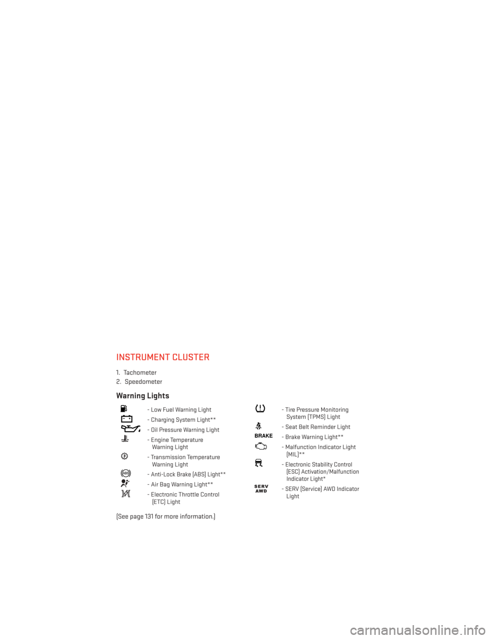
INSTRUMENT CLUSTER
1. Tachometer
2. Speedometer
Warning Lights
- Low Fuel Warning Light
- Charging System Light**
- Oil Pressure Warning Light
- Engine TemperatureWarning Light
- Transmission TemperatureWarning Light
-Anti-Lock Brake (ABS) Light**
- Air Bag Warning Light**
- Electronic Throttle Control(ETC) Light
- Tire Pressure MonitoringSystem (TPMS) Light
- Seat Belt Reminder Light
BRAKE- Brake Warning Light**
- Malfunction Indicator Light(MIL)**
-Electronic Stability Control(ESC) Activation/Malfunction
Indicator Light*
-SERV (Service) AWD Indicator Light
(See page 131 for more information.)
CONTROLS AT A GLANCE
8
Page 16 of 188
Accessory Positions With Engine Off
NOTE:
The following functions are with the driver’s foot OFF the Brake Pedal (transmission in PARK
or NEUTRAL).
Beginning With The Ignition Switch In The OFF Position:
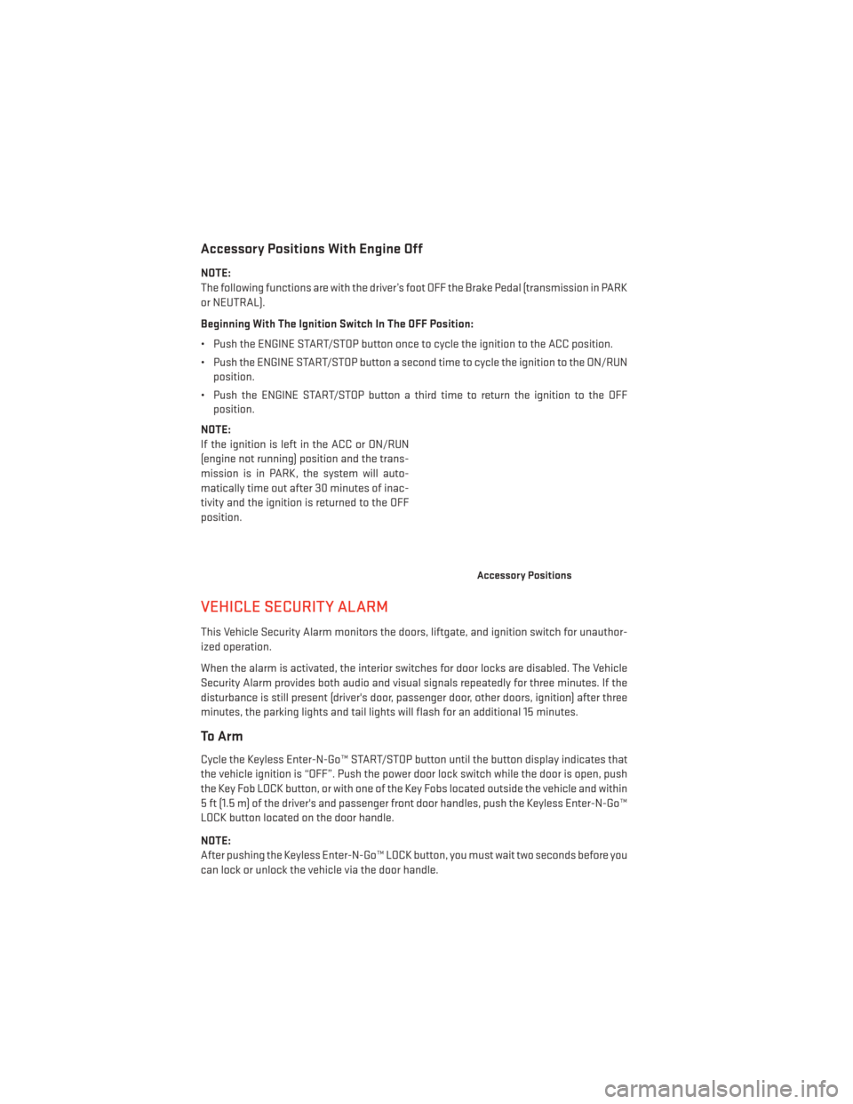
• Push the ENGINE START/STOP button once to cycle the ignition to the ACC position.
• Push the ENGINE START/STOP button a second time to cycle the ignition to the ON/RUNposition.
• Push the ENGINE START/STOP button a third time to return the ignition to the OFF position.
NOTE:
If the ignition is left in the ACC or ON/RUN
(engine not running) position and the trans-
mission is in PARK, the system will auto-
matically time out after 30 minutes of inac-
tivity and the ignition is returned to the OFF
position.
VEHICLE SECURITY ALARM
This Vehicle Security Alarm monitors the doors, liftgate, and ignition switch for unauthor-
ized operation.
When the alarm is activated, the interior switches for door locks are disabled. The Vehicle
Security Alarm provides both audio and visual signals repeatedly for three minutes. If the
disturbance is still present (driver's door, passenger door, other doors, ignition) after three
minutes, the parking lights and tail lights will flash for an additional 15 minutes.
To Arm
Cycle the Keyless Enter-N-Go™ START/STOP button until the button display indicates that
the vehicle ignition is “OFF”. Push the power door lock switch while the door is open, push
the Key Fob LOCK button, or with one of the Key Fobs located outside the vehicle and within
5 ft (1.5 m) of the driver's and passenger front door handles, push the Keyless Enter-N-Go™
LOCK button located on the door handle.
NOTE:
After pushing the Keyless Enter-N-Go™ LOCK button, you must wait two seconds before you
can lock or unlock the vehicle via the door handle.
Accessory Positions
GETTING STARTED
14
Page 118 of 188
Compass Calibration
This compass is self-calibrating, which eliminates the need to set the compass manually.
When the vehicle is new, the compass may appear erratic and the EVIC will display “CAL”
until the compass is calibrated.
You may also calibrate the compass by completing one or more 360 degree turns (in an area
free from large metal or metallic objects) until the “CAL” message displayed in the EVIC
turns off. The compass will now function normally.
ECO
The ECO message will appear in your EVIC display whenever you are driving in a fuel
efficient manner.
This feature allows you to monitor when you are driving in a fuel efficient manner, and it can
be used to modify driving habits in order to increase fuel economy.
PROGRAMMABLE FEATURES
EVIC Programmable Features
The EVIC can be used to view the following main menu items:
NOTE:
Depending on the vehicles options, feature settings may vary.
• Speedometer• Trip
• MPH to km/h • Audio
• Vehicle Info • Stored Messages
• Driver Assist • Screen Setup
• Fuel Economy • Speed Warning - If Equipped
NOTE:
Refer to your Owner's Manual on the DVD for further information.
Uconnect® Customer Programmable Features
The Uconnect® system allows you to access Customer Programmable feature settings
such as Display, Clock, Safety/Assistance, Lights, Doors & Locks, Auto-On Comfort &
Remote Start, Engine Off Operation, Compass Settings, Audio, Trailer Brake, Phone/
Bluetooth®, Suspension and SiriusXM Setup and System Information through soft-keys.
• Press the SETTINGS button (Uconnect® 5.0), or press the “Apps” button (Uconnect® 8.4)
located near the bottom of the touchscreen, then press the “Settings” button on the
touchscreen to access the Settings screen. When making a selection, scroll up or down
until the preferred setting is highlighted, then press and release the preferred setting
until a check-mark appears next to the setting, showing that setting has been selected.
ELECTRONICS
116
Page 119 of 188
The following feature settings are available:
• Display• Clock
• Safety/Assistance • Doors & Locks
• Auto-On Comfort & Remote Start • Engine Off Options
• Phone/Bluetooth® • Audio
• Lights • SiriusXM Setup
• Compass (Uconnect® 5.0) • Trailer Brake
• Suspension • System Information
• Units • Voice
NOTE:
Depending on the vehicles options, feature settings may vary.
EVIC Screen Setup
The following settings allow you to change what information is displayed in the instrument
cluster as well as the location that information is displayed.
• Compass • Fuel Economy Info
• Date • Speed
• Time • Range to Empty
• Outside Temp
Trip A
• Press and release the UP or DOWN arrow button until the Trip A icon is highlighted in the EVIC (Toggle left or right to select Trip A or Trip B). Press and release the OK button to
display the Trip A information.
Trip B
• Press and release the UP or DOWN arrow button until the Trip B icon is highlighted in theEVIC (Toggle left or right to select Trip A or Trip B). Press and release the OK button to
display the Trip B information.
Fuel Economy
Press and release the UP or DOWN arrow button until the Fuel Economy icon is highlighted.
Press the RIGHT arrow button and the next screen will display the following:
• Average Fuel Economy/Miles Per Gallon (MPG Bargraph)
• Range To Empty (RTE)
• Current Miles Per Gallon (MPG)
ELECTRONICS
117
Page 125 of 188
ALL-WHEEL DRIVE OPERATION
Single-Speed Operating Instructions/Precautions
This system contains a single-speed (HI range only) transfer case, which provides conve-
nient full-time all-wheel drive. No driver interaction is required. The Brake Traction Control
(BTC) System, which combines standard ABS and Traction Control, provides resistance to
any wheel that is slipping to allow additional torque transfer to wheels with traction.
NOTE:
This system is not appropriate for conditions where AWD LOW range is recommended. Refer to
“Off-Road Driving Tips” in “Starting and Operating” on the DVD for further information.
Electronically Shifted Transfer Case (Three-Position Switch)
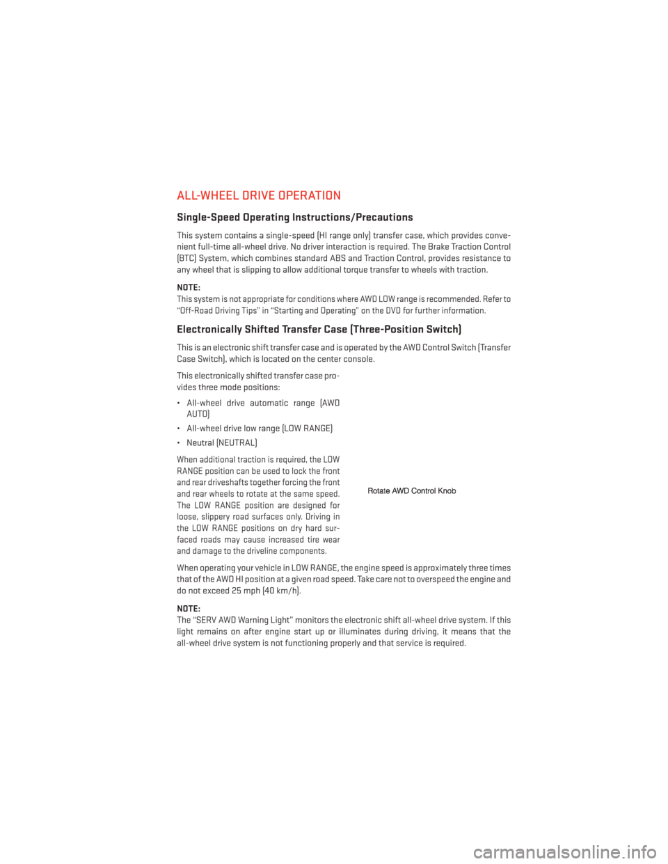
This is an electronic shift transfer case and is operated by the AWD Control Switch (Transfer
Case Switch), which is located on the center console.
This electronically shifted transfer case pro-
vides three mode positions:
• All-wheel drive automatic range (AWDAUTO)
• All-wheel drive low range (LOW RANGE)
• Neutral (NEUTRAL)
When additional traction is required, the LOW
RANGE position can be used to lock the front
and rear driveshafts together forcing the front
and rear wheels to rotate at the same speed.
The LOW RANGE position are designed for
loose, slippery road surfaces only. Driving in
the LOW RANGE positions on dry hard sur-
faced roads may cause increased tire wear
and damage to the driveline components.
When operating your vehicle in LOW RANGE, the engine speed is approximately three times
that of the AWD HI position at a given road speed. Take care not to overspeed the engine and
do not exceed 25 mph (40 km/h).
NOTE:
The “SERV AWD Warning Light” monitors the electronic shift all-wheel drive system. If this
light remains on after engine start up or illuminates during driving, it means that the
all-wheel drive system is not functioning properly and that service is required.
OFF-ROAD CAPABILITIES
123
Page 126 of 188
Shifting Procedures
AWD Auto To Low Range
NOTE:
When shifting into or out of LOW RANGE some gear noise may be heard. This noise is
normal and is not detrimental to the vehicle or occupants.
• Shifting can be performed with the vehicle rolling 2 to 3 mph (3 to 5 km/h) or completelystopped. Use either of the following procedures:
Preferred Procedure
1. With the engine running, slow the vehicle to 2 to 3 mph (3 to 5 km/h).
2. Shift the transmission into NEUTRAL.
3. While still rolling, rotate the transfer case control switch to the desired position.
4. After the desired position indicator light is ON (not flashing), shift the transmission back into gear.
Alternate Procedure
1. Bring the vehicle to complete stop.
2. With the ignition switch in the ON position and the engine either OFF or running, shift the transmission into NEUTRAL.
3. Rotate the transfer case control switch to the desired position.
4. After the desired position indicator light is ON (not flashing), shift the transmission back into gear.
NOTE:
• If Steps 1 or 2 of either the Preferred or Alternate Procedure are not satisfied prior to attempting the shift or if they no longer are being met while the shift attempt is in
process, the desired position indicator light will flash continuously while the original
position indicator light is ON, until all requirements have been met.
• The ignition switch must be in the ON position for a shift to take place and for the position indicator lights to be operable. If the ignition switch is not in the ON position, then the
shift will not take place and no position indicator lights will be on or flashing.
WARNING!
• Always engage the parking brake when powering down the vehicle if the “SERV AWD
Warning Light” is illuminated. Not engaging the parking brake may allow the vehicle
to roll which may cause personal injury.
•
You or others could be injured if you leave the vehicle unattended with the transfer case
in the NEUTRAL position without first fully engaging the parking brake. The transfer case
NEUTRAL position disengages both the front and rear driveshafts from the powertrain
and will allow the vehicle to move regardless of the transmission position. The parking
brake should always be applied when the driver is not in the vehicle.
OFF-ROAD CAPABILITIES
124
Page 130 of 188
Shifting Into NEUTRAL
Use the following procedure to prepare your vehicle for recreational towing:
1. Bring the vehicle to a complete stop, with the engine running.
2. Press and hold the brake pedal.
3. Shift the transmission into NEUTRAL.
4. Using a ballpoint pen or similar object, press and hold the recessed transfer caseNEUTRAL (N) button (located by the selector switch) for four seconds. The light behind
the N symbol will blink, indicating shift in progress. The light will stop blinking (stay on
solid) when the shift to NEUTRAL (N) is complete. A “FOUR WHEEL DRIVE SYSTEM IN
NEUTRAL” message will display on the EVIC (Electronic Vehicle Information Center).
5. After the shift is completed and the NEUTRAL (N) light stays on, release the NEUTRAL (N) button.
6. Shift the transmission into REVERSE.
7. Release the brake pedal for five seconds and ensure that there is no vehicle movement.
8. Shift the transmission back into NEUTRAL.
9. Firmly apply the parking brake.
10. With the transmission and transfer case in NEUTRAL, press and hold the ENGINE START/STOP button until the engine turns off. Turning the engine off will automatically
place the transmission in PARK.
11.
Press the ENGINE STOP/START button again (without pressing the brake pedal), if needed,
to turn the ignition switch to the OFF position.
CAUTION!
Damage to the transmission may occur if the transmission is shifted into PARK with the
transfer case in NEUTRAL (N) and the engine running. With the transfer case in NEUTRAL
(N) ensure that the engine is OFF before shifting the transmission into PARK.
12. Attach the vehicle to the tow vehicle using a suitable tow bar.
13. Release the parking brake.
UTILITY
128
Page 131 of 188
NOTE:
• Steps 1 through 3 are requirements that must be met before pressing the NEUTRAL (N)button, and must continue to be met until the shift has been completed. If any of these
requirements are not met before pressing the NEUTRAL (N) button or are no longer met
during the shift, the NEUTRAL (N) indicator light will flash continuously until all require-
ments are met or until the NEUTRAL (N) button is released.
• The ignition switch must be in the ON/RUN position for a shift to take place and for the position indicator lights to be operable. If the ignition switch is not in the ON/RUN
position, the shift will not take place and no position indicator lights will be on or flashing.
• A flashing NEUTRAL (N) position indicator light indicates that shift requirements have not been met.
CAUTION!
•Towing with the rear wheels on the ground will cause severe transmission damage.
Damage from improper towing is not covered under the New Vehicle Limited Warranty.
• Front or rear wheel lifts should not be used. Internal damage to the transmission or
transfer case will occur if a front or rear wheel lift is used when recreational towing.
• It is necessary to follow these steps to be certain that the transfer case is fully in NEUTRAL before recreational towing to prevent damage to internal parts.
WARNING!
You or others could be injured if you leave the vehicle unattended with the transfer case
in the NEUTRAL position without first fully engaging the parking brake. The transfer case
NEUTRAL position disengages both the front and rear driveshafts from the powertrain
and will allow the vehicle to move even if the transmission is in PARK. The parking brake
should always be applied when the driver is not in the vehicle.
UTILITY
129
Page 132 of 188
Shifting Out Of NEUTRAL (N)
Use the following procedure to prepare your vehicle for normal usage:
1. Bring the vehicle to a complete stop, leaving it connected to the tow vehicle.
2. Firmly apply the parking brake.
3. Start the engine.
4. Press and hold the brake pedal.
5. Shift the transmission into NEUTRAL.
6. Using a ballpoint pen or similar object, press and hold the recessed transfer caseNEUTRAL (N) button (located by the selector switch) for one second.
7. When the NEUTRAL (N) indicator light turns off, release the NEUTRAL (N) button.
8. After the NEUTRAL (N) button has been released, the transfer case will shift to the position indicated by the selector switch.
9. Shift the transmission into PARK and turn the engine OFF.
10. Release the brake pedal.
11. Disconnect vehicle from the tow vehicle.
12. Start the engine.
13. Press and hold the brake pedal.
14. Release the parking brake.
15. Shift the transmission into DRIVE, release the brake pedal, and check that the vehicle operates normally.
NOTE:
• Steps 1 through 5 are requirements that must be met before pressing the NEUTRAL (N) button, and must continue to be met until the shift has been completed. If any of these
requirements are not met before pressing the NEUTRAL (N) button or are no longer met
during the shift, the NEUTRAL (N) indicator light will flash continuously until all require-
ments are met or until the NEUTRAL (N) button is released.
• The ignition switch must be in the ON/RUN position for a shift to take place and for the position indicator lights to be operable. If the ignition switch is not in the ON/RUN
position, the shift will not take place and no position indicator lights will be on or flashing.
• A flashing NEUTRAL (N) position indicator light indicates that shift requirements have not been met.
UTILITY
130
Page 134 of 188
When the malfunction indicator is illuminated, the system may not be able to detect or
signal low tire pressure as intended. TPMS malfunctions may occur for a variety of reasons,
including the installation of replacement or alternate tires or wheels on the vehicle that
prevent the TPMS from functioning properly. Always check the TPMS malfunction telltale
after replacing one or more tires or wheels on your vehicle, to ensure that the replacement
or alternate tires and wheels allow the TPMS to continue to function properly.
NOTE:
Tire pressures change by approximately 1 psi (7 kPa) per 12° F (7° C) of air temperature
change. Keep this in mind when checking tire pressure inside a garage, especially in the
Winter. Example: If garage temperature is 68°F (20°C) and the outside temperature is 32°F
(0°C), then the cold tire inflation pressure should be increased by 3 psi (21 kPa), which equals
1 psi (7 kPa) for every 12°F (7°C) for this outside temperature condition.
CAUTION!
The TPMS has been optimized for the original equipment tires and wheels. TPMS
pressures and warning have been established for the tire size equipped on your vehicle.
Undesirable system operation or sensor damage may result when using replacement
equipment that is not of the same size, type, and/or style. Aftermarket wheels can cause
sensor damage. Do not use tire sealant from a can, or balance beads if your vehicle is
equipped with a TPMS, as damage to the sensors may result.
BRAKE- Brake Warning Light
This light monitors various brake functions, including brake fluid level and parking brake
application. If the brake light turns on it may indicate that the parking brake is applied, that the
brake fluid level is low, or that there is a problem with the anti-lock brake system reservoir.
If the light remains on when the parking brake has been disengaged, and the fluid level is at
the full mark on the master cylinder reservoir, it indicates a possible brake hydraulic system
malfunction or that a problem with the Brake Booster has been detected by the Anti-Lock
Brake System (ABS)/Electronic Stability Control (ESC) system. In this case, the light will
remain on until the condition has been corrected. If the problem is related to the brake
booster, the ABS pump will run when applying the brake and a brake pedal pulsation may be
felt during each stop.
The dual brake system provides a reserve braking capacity in the event of a failure to a
portion of the hydraulic system. A leak in either half of the dual brake system is indicated by
the Brake Warning Light, which will turn on when the brake fluid level in the master cylinder
has dropped below a specified level. The light will remain on until the cause is corrected.
Vehicles equipped with the Anti-Lock Brake System (ABS), are also equipped with Electronic
Brake Force Distribution (EBD). In the event of an EBD failure, the Brake Warning Light will
turn on along with the ABS Light. Immediate repair to the ABS system is required.
WHAT TO DO IN EMERGENCIES
132