steering wheel DODGE DURANGO 2015 3.G User Guide
[x] Cancel search | Manufacturer: DODGE, Model Year: 2015, Model line: DURANGO, Model: DODGE DURANGO 2015 3.GPages: 236, PDF Size: 35.01 MB
Page 3 of 236
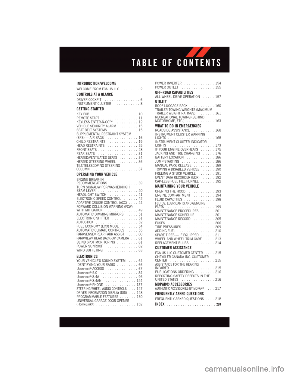
INTRODUCTION/WELCOME
WELCOME FROM FCA US LLC.......2
CONTROLS AT A GLANCE
DRIVER COCKPIT...............6INSTRUMENT CLUSTER...........8
GETTING STARTED
KEY FOB . . . . . . . . . . . . . . . . . . . 10REMOTE START . . . . . . . . . . . . . . . . 11KEYLESS ENTER-N-GO™.........12VEHICLE SECURITY ALARM........15SEAT BELT SYSTEMS............15SUPPLEMENTAL RESTRAINT SYSTEM(SRS) — AIR BAGS.............16CHILD RESTRAINTS............19HEAD RESTRAINTS.............25FRONT SEATS.................28REAR SEATS.................31HEATED/VENTILATED SEATS........34HEATED STEERING WHEEL........36TILT/TELESCOPING STEERINGCOLUMN...................37
OPERATING YOUR VEHICLE
ENGINE BREAK-INRECOMMENDATIONS............39TURN SIGNAL/WIPER/WASHER/HIGHBEAM LEVER.................40HEADLIGHT SWITCH............41ELECTRONIC SPEED CONTROL......42ADAPTIVE CRUISE CONTROL (ACC)....44FORWARD COLLISION WARNING (FCW)WITH MITIGATION..............49AUTOMATIC DIMMING MIRRORS.....51ELECTRONIC SHIFTER...........51AUTOSTICK..................52FUEL ECONOMY (ECO) MODE.......54AUTOMATIC CLIMATE CONTROLS.....55PA R K S E N S E®REAR PARK ASSIST.....60PA R K V I E W®REAR BACK-UP CAMERA...61BLIND SPOT MONITORING.........61POWER SUNROOF..............62WIND BUFFETING..............63
ELECTRONICSYOUR VEHICLE'S SOUND SYSTEM....64IDENTIFYING YOUR RADIO.........66Uconnect®ACCESS.............67Uconnect®5.0 . . . . . . . . . . . . . . . . 84Uconnect®8.4A...............96Uconnect®8.4AN.............124Uconnect®PHONE.............137STEERING WHEEL AUDIO CONTROLS...147DRIVER INFORMATION DISPLAY (DID)...148PROGRAMMABLE FEATURES.......150UNIVERSAL GARAGE DOOR OPENER(HomeLink®).................152
POWER INVERTER.............154POWER OUTLET..............155
OFF-ROAD CAPABILITIESALL-WHEEL DRIVE OPERATION.....157
UTILITYROOF LUGGAGE RACK..........160TRAILER TOWING WEIGHTS (MAXIMUMTRAILER WEIGHT RATINGS).......161RECREATIONAL TOWING (BEHINDMOTORHOME, ETC.)............163
WHAT TO DO IN EMERGENCIESROADSIDE ASSISTANCE..........168INSTRUMENT CLUSTER WARNINGLIGHTS....................168INSTRUMENT CLUSTER INDICATORLIGHTS...................173IF YOUR ENGINE OVERHEATS......175JACKING AND TIRE CHANGING.....176BATTERY LOCATION............186JUMP-STARTING..............186MANUAL PARK RELEASE.........189TOWING A DISABLED VEHICLE.....190FREEING A STUCK VEHICLE.......191EVENT DATA RECORDER (EDR).....192CAP-LESS FUEL FILL FUNNEL......192
MAINTAINING YOUR VEHICLE
OPENING THE HOOD...........193ENGINE COMPARTMENT.........194FLUID CAPACITIES.............198FLUIDS, LUBRICANTS AND GENUINEPA RT S....................199MAINTENANCE PROCEDURES......201MAINTENANCE SCHEDULE.......201MAINTENANCE RECORD.........205FUSES....................206TIRE PRESSURES.............209ADDING FUEL................210SPARE TIRES — IF EQUIPPED......211WHEEL AND WHEEL TRIM CARE....213REPLACEMENT BULBS..........214
CUSTOMER ASSISTANCE
FCA US LLC CUSTOMER CENTER....215CHRYSLER CANADA INC. CUSTOMERCENTER...................215ASSISTANCE FOR THE HEARINGIMPAIRED..................215PUBLICATIONS ORDERING........216REPORTING SAFETY DEFECTS IN THEUNITED STATES..............216
MOPAR® ACCESSORIESAUTHENTIC ACCESSORIES BY MOPAR®...217
FREQUENTLY ASKED QUESTIONS
FREQUENTLY ASKED QUESTIONS....218
INDEX.....................220
TABLE OF CONTENTS
Page 8 of 236
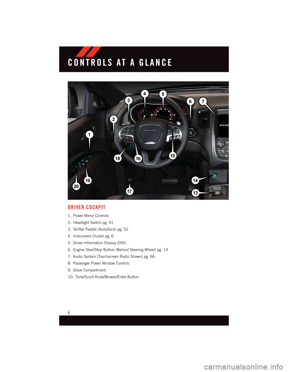
DRIVER COCKPIT
1. Power Mirror Controls
2. Headlight Switch pg. 41
3. Shifter Paddle (AutoStick) pg. 52
4. Instrument Cluster pg. 6
5. Driver Information Display (DID)
6. Engine Start/Stop Button (Behind Steering Wheel) pg. 14
7. Audio System (Touchscreen Radio Shown) pg. 66
8. Passenger Power Window Controls
9. Glove Compartment
10. Tune/Scroll Knob/Browse/Enter Button.
CONTROLS AT A GLANCE
6
Page 18 of 236
WARNING!
•Inacollision,youandyourpassengerscansuffermuchgreaterinjuriesifyouare
not properly buckled up. You can strike the interior of your vehicle or other
passengers, or you can be thrown out of the vehicle. Always be sure you and others
in your vehicle are buckled up properly.
•Ashoulderbeltplacedbehindyouwillnotprotectyoufrominjuryduringacollision.
Yo u a r e m o r e l i k e l y t o h i t y o u r h e a d i n a c o l l i s i o n i f y o u d o n o t w e a r y o u r s h o u l d e r
belt. The lap and shoulder belt are meant to be used together.
•Aseatbeltthatistooloosewillnotprotectyouproperly.Inasuddenstop,youcould
move too far forward, increasing the possibility of injury. Wear your seat belt snugly.
•Afrayedortornseatbeltcouldripapartinacollisionandleaveyouwithno
protection. Inspect the seat belt system periodically, checking for cuts, frays, or
loose parts. Damaged parts must be replaced immediately. Do not disassemble or
modify the system. Seat belt assemblies must be replaced after a collision.
SUPPLEMENTAL RESTRAINT SYSTEM (SRS) — AIR BAGS
Air Bag System Components
Yo u r v e h i c l e m a y b e e q u i p p e d w i t h t h e f o l l o w i n g a i r b a g s y s t e m c o m p o n e n t s :
•OccupantRestraintController(ORC)
•AirBagWarningLight
•SteeringWheelandColumn
•InstrumentPanel
•KneeImpactBolsters
•AdvancedFrontAirBags
•SupplementalSideAirBags
•SupplementalKneeAirBags
•FrontandSideImpactSensors
•SeatBeltPretentioners
•SeatBeltBuckleSwitch
•SeatTrackPositionSensors
Advanced Front Air Bags
•ThisvehiclehasAdvancedFrontAirBagsforboththedriverandfrontpassengerasa
supplement to the seat belt restraint systems. The Advanced Front Air Bags will not
deploy in every type of collision.
•AdvancedFrontAirBagsaredesignedtoprovideadditionalprotectionbysupplement-
ing the seat belts. Advanced Front Air Bags are not expected to reduce the risk of injury
in rear, side, or rollover collisions.
GETTING STARTED
16
Page 20 of 236
Supplemental Knee Air Bags
This vehicle is equipped with a Supplemental Driver Knee Air Bag mounted in the
instrument panel below the steering column. The Supplemental Driver Knee Air Bag
provides enhanced protection during a frontal impact by working together with the seat
belts, pretensioners, and Advanced Front Air Bags.
WARNING!
•Relyingontheairbagsalonecouldleadtomoresevereinjuriesinacollision.The
air bags work with your seat belt to restrain you properly. In some collisions, the air
bags won't deploy at all. Always wear your seat belts even though you have air bags.
•BeingtooclosetothesteeringwheelorinstrumentpanelduringAdvancedFrontAir
Bag deployment could cause serious injury, including death. Air bags need room to
inflate. Sit back, comfortably extending your arms to reach the steering wheel or
instrument panel.
•Noobjectsshouldbeplacedoverorneartheairbagontheinstrumentpanelor
steering wheel because any such objects could cause harm if the vehicle is in a
collision severe enough to cause the air bag to inflate.
Supplemental Side Air Bags
•ThisvehicleisequippedwithSupplementalSeat-MountedSideAirBags(SABs)
located in the outboard side of the front seats. The SABs are marked with a SRS
AIRBAG or AIRBAG label sewn into the outboard side of the seats.
•ThisvehicleisequippedwithSupplementalSideAirBagInflatableCurtains(SABICs)
located above the side windows. The trim covering the SABICs is labeled SRS AIRBAG
or AIRBAG. The SABICs may help reduce the risk of partial or complete ejection of
vehicle occupants through side windows in certain side impact events.
•TheSABICsandSABs(“SideAirBags”)aredesignedtoactivateincertainside
impacts and certain rollover events. The Occupant Restraint Controller (“ORC”)
determines whether the deployment of the Side Air Bags in a particular side impact or
rollover event is appropriate, based on the severity and type of collision. Vehicle damage
by itself is not a good indicator of whether or not Side Air Bags should have deployed.
GETTING STARTED
18
Page 38 of 236
HEATED STEERING WHEEL
The steering wheel contains a heating element that heats the steering wheel to one
temperature setting.
The heated steering wheel control button is located within the Uconnect®system. You can
gain access to the control buttons through the climate screen or the controls screen.
•Presstheheatedsteeringwheelbuttononce to turn the heating element ON.
•Presstheheatedsteeringwheelbuttonasecondtimetoturntheheatingelement
OFF.
Once the heated steering wheel has been turned on, it will operate for up to 80 minutes
before automatically shutting off. The heated steering wheel can shut off early or may not
turn on when the steering wheel is already warm.
NOTE:
On models that are equipped with Remote Start, this feature can be programmed to come
on during a Remote Start through the Uconnect®system. Refer to “Uconnect®Settings”
in “Understanding Your Instrument Panel” in the Owner's Manual on the DVD.
WARNING!
•Personswhoareunabletofeelpaintotheskinbecauseofadvancedage,chronic
illness, diabetes, spinal cord injury, medication, alcohol use, exhaustion, or other
physical conditions must exercise care when using the steering wheel heater. It may
cause burns even at low temperatures, especially if used for long periods.
•Donotplaceanythingonthesteeringwheelthatinsulatesagainstheat,suchasa
blanket or steering wheel covers of any type and material. This may cause the
steering wheel heater to overheat.
GETTING STARTED
36
Page 39 of 236
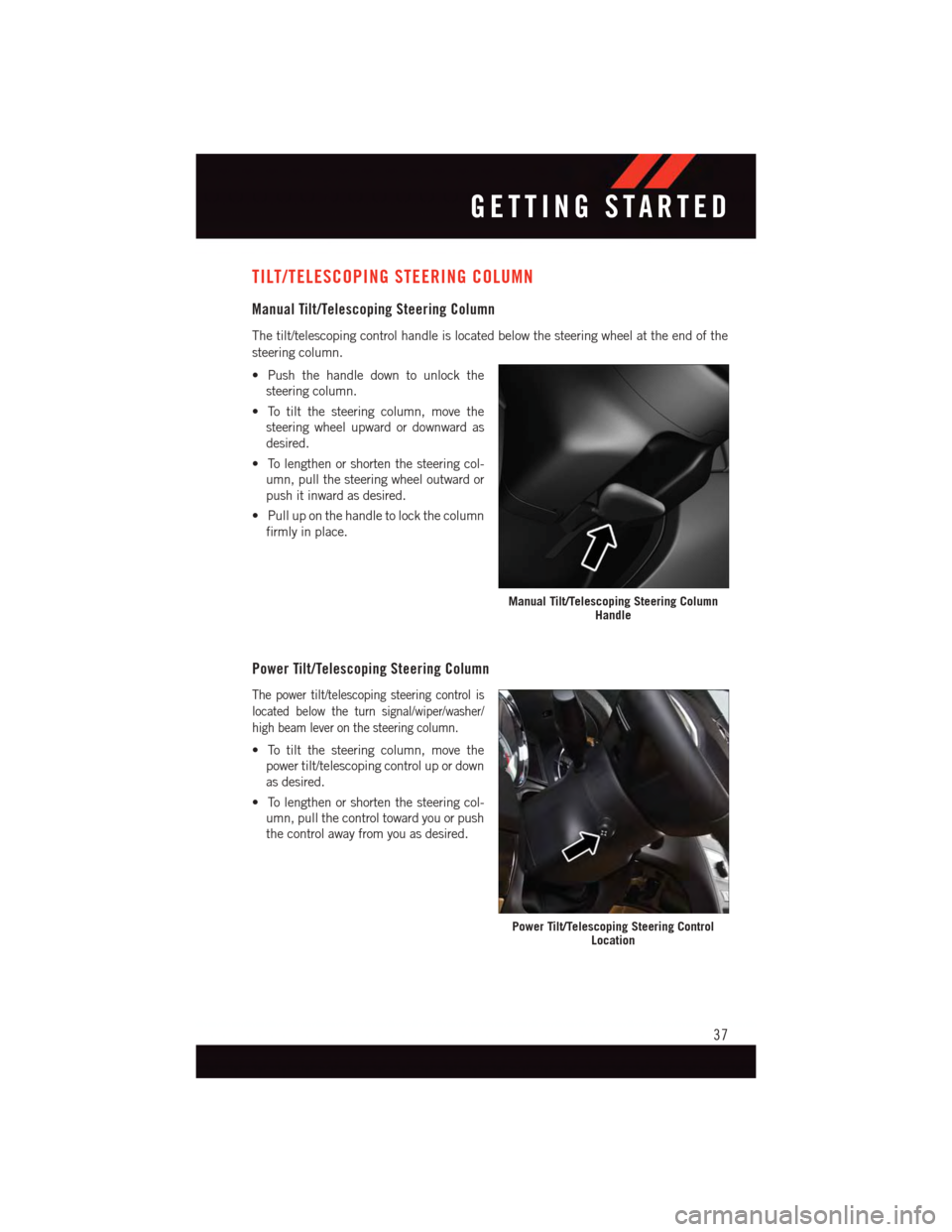
TILT/TELESCOPING STEERING COLUMN
Manual Tilt/Telescoping Steering Column
The tilt/telescoping control handle is located below the steering wheel at the end of the
steering column.
•Pushthehandledowntounlockthe
steering column.
•Totiltthesteeringcolumn,movethe
steering wheel upward or downward as
desired.
•Tolengthenorshortenthesteeringcol-
umn, pull the steering wheel outward or
push it inward as desired.
•Pulluponthehandletolockthecolumn
firmly in place.
Power Tilt/Telescoping Steering Column
The power tilt/telescoping steering control is
located below the turn signal/wiper/washer/
high beam lever on the steering column.
•Totiltthesteeringcolumn,movethe
power tilt/telescoping control up or down
as desired.
•Tolengthenorshortenthesteeringcol-
umn, pull the control toward you or push
the control away from you as desired.
Manual Tilt/Telescoping Steering ColumnHandle
Power Tilt/Telescoping Steering ControlLocation
GETTING STARTED
37
Page 40 of 236
WARNING!
•Donotadjustthesteeringwheelwhiledriving.Thetilt/telescopingadjustmentmust
be locked while driving. Adjusting the steering wheel while driving or driving
without the tilt/telescoping adjustment locked could cause the driver to lose control
of the vehicle. Failure to follow this warning may result in you and others being
severely injured or killed.
•Movingthesteeringcolumnwhilethevehicleismovingisdangerous.Withouta
stable steering column, you could lose control of the vehicle and have a collision.
Adjust the column only while the vehicle is stopped.
GETTING STARTED
38
Page 43 of 236
Rear Wiper
Rear Wiper Operation
Rotate the center portion of the lever forward to the first detent for intermittent operation
and to the second detent for rear wiper operation.
Rear Washer Operation
Rotate the center portion of the lever past the second detent to activate the rear washer.
High Beam Operation
Push the lever forward to activate the high beams. Pull the lever toward you for flash to
pass.
NOTE:
For safe driving, turn off high beams when oncoming traffic is present to prevent headlight
glare and as a courtesy to other motorists.
HEADLIGHT SWITCH
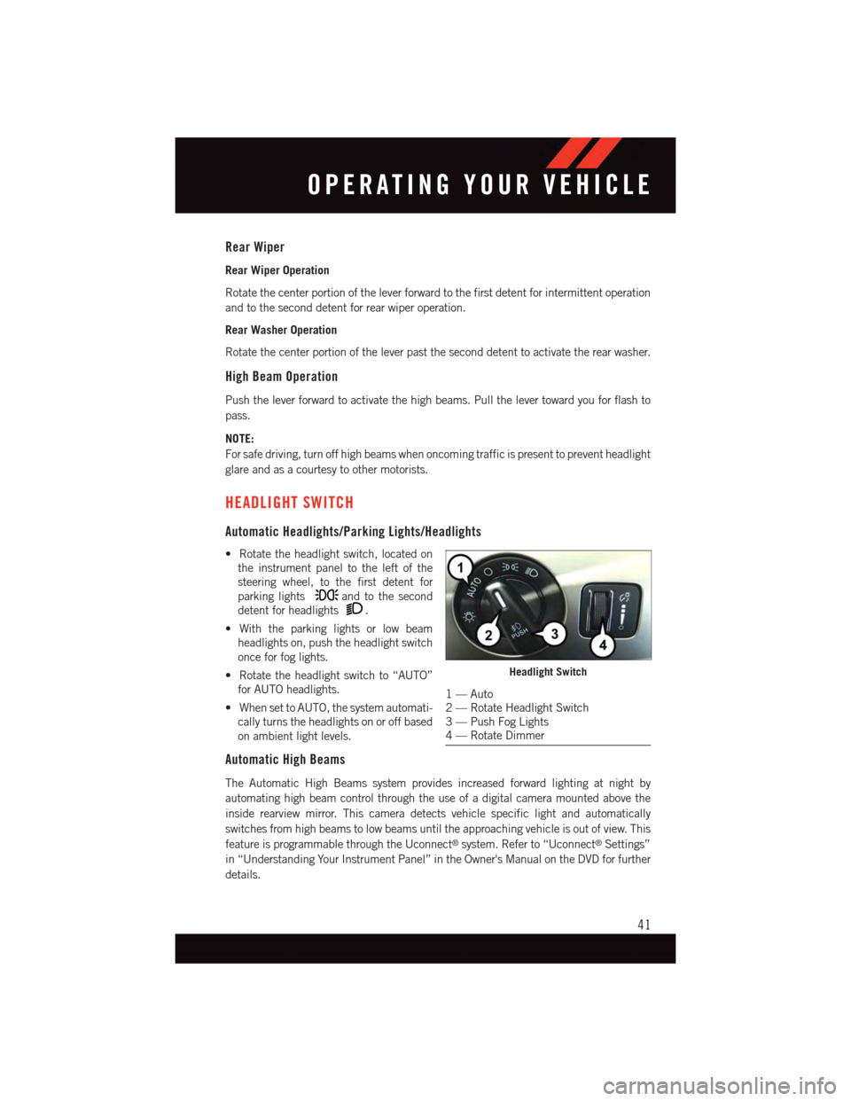
Automatic Headlights/Parking Lights/Headlights
•Rotatetheheadlightswitch,locatedon
the instrument panel to the left of the
steering wheel, to the first detent for
parking lightsand to the second
detent for headlights.
•Withtheparkinglightsorlowbeam
headlights on, push the headlight switch
once for fog lights.
•Rotatetheheadlightswitchto“AUTO”
for AUTO headlights.
•WhensettoAUTO,thesystemautomati-
cally turns the headlights on or off based
on ambient light levels.
Automatic High Beams
The Automatic High Beams system provides increased forward lighting at night by
automating high beam control through the use of a digital camera mounted above the
inside rearview mirror. This camera detects vehicle specific light and automatically
switches from high beams to low beams until the approaching vehicle is out of view. This
feature is programmable through the Uconnect®system. Refer to “Uconnect®Settings”
in “Understanding Your Instrument Panel” in the Owner's Manual on the DVD for further
details.
Headlight Switch
1—Auto2—RotateHeadlightSwitch3—PushFogLights4—RotateDimmer
OPERATING YOUR VEHICLE
41
Page 44 of 236
Instrument Panel Dimmer
•Rotatethedimmercontroltotheextremebottompositiontofullydimtheinstrument
panel lights and prevent the interior lights from illuminating when a door is opened.
•Rotatethedimmercontroluptoincreasethebrightnessoftheinstrumentpanelwhen
the parking lights or headlights are on.
•Rotatethedimmercontroluptothenextdetentpositiontofullybrightentheodometer
and radio when the parking lights or headlights are on.
•Rotatethedimmercontroluptothelastdetentpositiontoturnontheinteriorlighting.
If your vehicle is equipped with a touchscreen, the dimming is programmable through the
Uconnect®system. Refer to “Uconnect®Settings ” in “Understanding Your Instrument
Panel” in the Owner's Manual on the DVD for further details.
ELECTRONIC SPEED CONTROL
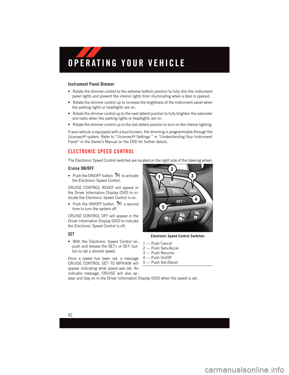
The Electronic Speed Control switches are located on the right side of the steering wheel.
Cruise ON/OFF
•PushtheON/OFFbuttonto activate
the Electronic Speed Control.
CRUISE CONTROL READY will appear in
the Driver Information Display (DID) to in-
dicate the Electronic Speed Control is on.
•PushtheON/OFFbuttonasecond
time to turn the system off.
CRUISE CONTROL OFF will appear in the
Driver Information Display (DID) to indicate
the Electronic Speed Control is off.
SET
•WiththeElectronicSpeedControlon,
push and release the SET+ or SET- but-
ton to set a desired speed.
Once a speed has been set, a message
CRUISE CONTROL SET TO MPH/KM will
appear indicating what speed was set. An
indicator message, CRUISE will also ap-
pear and stay on in the Driver Information Display (DID) when the speed is set.
Electronic Speed Control Switches
1—PushCancel2—PushSet+/Accel3—PushResume4—PushOn/Off5—PushSet-/Decel
OPERATING YOUR VEHICLE
42
Page 55 of 236
Operation
When the transmission is in DRIVE, it will operate automatically, shifting between the
eight available gears. To engage AutoStick, simply tap one of the steering wheel-mounted
shift paddles (+/-). Tapping (-) to enter AutoStick mode will downshift the transmission to
the next lower gear, while using (+) to enter AutoStick mode will retain the current gear.
When AutoStick is active, the current transmission gear is displayed in the instrument
cluster.
In AutoStick mode, the transmission will shift up or down when (+/-) is manually selected
by the driver, unless an engine lugging or overspeed condition would result. It will remain
in the selected gear until another upshift or downshift is chosen, except as described
below.
•Thetransmissionwillautomaticallydownshiftasthevehicleslows(topreventengine
lugging) and will display the current gear.
•Thetransmissionwillautomaticallydownshifttofirstgearwhencomingtoastop.After
astop,thedrivershouldmanuallyupshift(+)thetransmissionasthevehicleis
accelerated.
•Youcanstartout,fromastop,infirstorsecondgear.Tapping(+)atastopwillallow
starting in second gear. Starting out in second gear can be helpful in snowy or icy
conditions.
•Ifarequesteddownshiftwouldcausetheenginetoover-speed,thatshiftwillnotoccur.
•Thesystemwillignoreattemptstoupshiftattoolowofavehiclespeed.
•Holdingthe(-)paddledepressedwilldownshiftthetransmissiontothelowestgear
possible at the current speed.
•TransmissionshiftingwillbemorenoticeablewhenAutoStickisengaged.
•Thesystemmayreverttoautomaticshiftmodeifafaultoroverheatconditionis
detected.
To d i s e n g a g e A u t o S t i c k m o d e , p r e s s a n d h o l d t h e ( + ) s h i f t p a d d l e u n t i l " D " i s o n c e a g a i n
indicated in the instrument cluster. You can shift in or out of AutoStick mode at any time
without taking your foot off the accelerator pedal.
WARNING!
Do not downshift for additional engine braking on a slippery surface. The drive wheels
could lose their grip and the vehicle could skid, causing a collision or personal injury.
OPERATING YOUR VEHICLE
53