radio DODGE DURANGO 2020 Owner's Guide
[x] Cancel search | Manufacturer: DODGE, Model Year: 2020, Model line: DURANGO, Model: DODGE DURANGO 2020Pages: 464, PDF Size: 22.14 MB
Page 158 of 464
156SAFETY
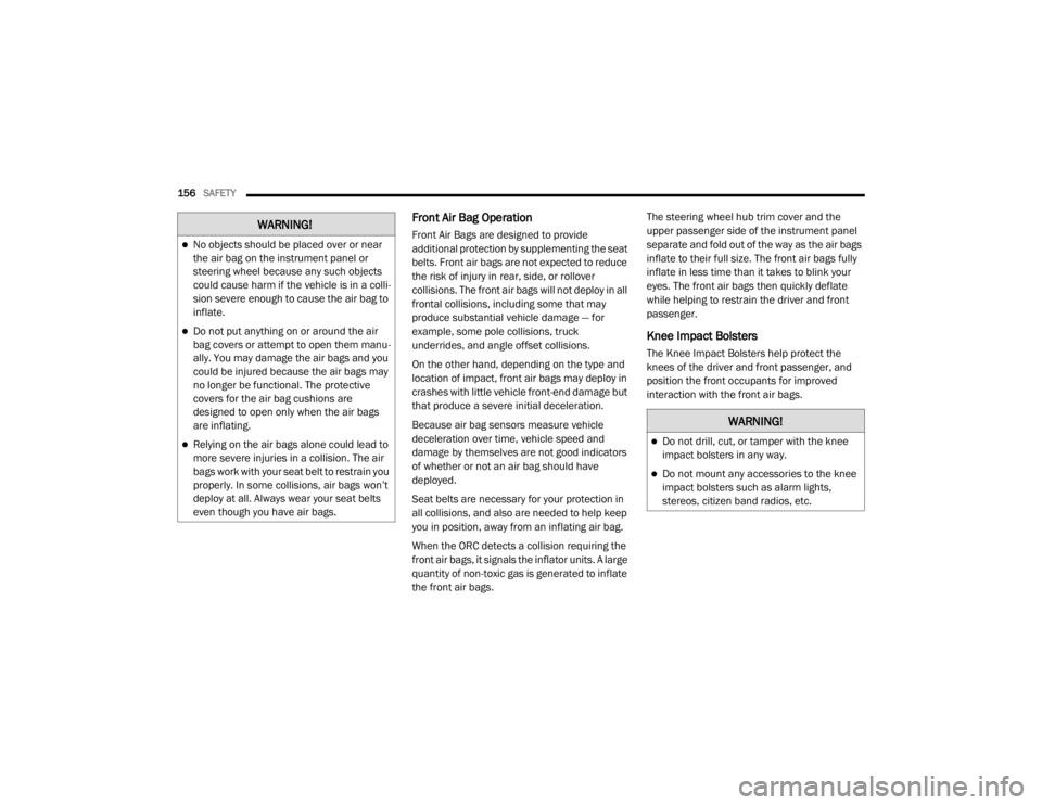
Front Air Bag Operation
Front Air Bags are designed to provide
additional protection by supplementing the seat
belts. Front air bags are not expected to reduce
the risk of injury in rear, side, or rollover
collisions. The front air bags will not deploy in all
frontal collisions, including some that may
produce substantial vehicle damage — for
example, some pole collisions, truck
underrides, and angle offset collisions.
On the other hand, depending on the type and
location of impact, front air bags may deploy in
crashes with little vehicle front-end damage but
that produce a severe initial deceleration.
Because air bag sensors measure vehicle
deceleration over time, vehicle speed and
damage by themselves are not good indicators
of whether or not an air bag should have
deployed.
Seat belts are necessary for your protection in
all collisions, and also are needed to help keep
you in position, away from an inflating air bag.
When the ORC detects a collision requiring the
front air bags, it signals the inflator units. A large
quantity of non-toxic gas is generated to inflate
the front air bags. The steering wheel hub trim cover and the
upper passenger side of the instrument panel
separate and fold out of the way as the air bags
inflate to their full size. The front air bags fully
inflate in less time than it takes to blink your
eyes. The front air bags then quickly deflate
while helping to restrain the driver and front
passenger.
Knee Impact Bolsters
The Knee Impact Bolsters help protect the
knees of the driver and front passenger, and
position the front occupants for improved
interaction with the front air bags.
WARNING!
No objects should be placed over or near
the air bag on the instrument panel or
steering wheel because any such objects
could cause harm if the vehicle is in a colli
-
sion severe enough to cause the air bag to
inflate.
Do not put anything on or around the air
bag covers or attempt to open them manu -
ally. You may damage the air bags and you
could be injured because the air bags may
no longer be functional. The protective
covers for the air bag cushions are
designed to open only when the air bags
are inflating.
Relying on the air bags alone could lead to
more severe injuries in a collision. The air
bags work with your seat belt to restrain you
properly. In some collisions, air bags won’t
deploy at all. Always wear your seat belts
even though you have air bags.
WARNING!
Do not drill, cut, or tamper with the knee
impact bolsters in any way.
Do not mount any accessories to the knee
impact bolsters such as alarm lights,
stereos, citizen band radios, etc.
20_WD_OM_EN_USC_t.book Page 156
Page 221 of 464
STARTING AND OPERATING219
GENERAL INFORMATION
The following regulatory statement applies to all
Radio Frequency (RF) devices equipped in this
vehicle:
This device complies with Part 15 of the FCC
Rules and with Innovation, Science and
Economic Development Canada license-exempt
RSS standard(s). Operation is subject to the
following two conditions:
1. This device may not cause harmful
interference, and
2. This device must accept any interference received, including interference that may
cause undesired operation.
Le présent appareil est conforme aux CNR
d`Innovation, Science and Economic
Development applicables aux appareils radio
exempts de licence. L'exploitation est autorisée
aux deux conditions suivantes:
1. l'appareil ne doit pas produire de brouillage, et
2. l'utilisateur de l'appareil doit accepter tout
brouillage radioélectrique subi, même si le
brouillage est susceptible d'en compro -
mettre le fonctionnement.
La operación de este equipo está sujeta a las
siguientes dos condiciones:
1. es posible que este equipo o dispositivo no cause interferencia perjudicial y
2. este equipo o dispositivo debe aceptar cualquier interferencia, incluyendo la que
pueda causar su operación no deseada.
NOTE:
Changes or modifications not expressly
approved by the party responsible for compli -
ance could void the user’s authority to operate
the equipment.
NORMAL (FIXED SPEED) CRUISE
C
ONTROL MODE
In addition to Adaptive Cruise Control mode, a
Normal (Fixed Speed) Cruise Control mode is
available for cruising at fixed speeds. The Normal (Fixed Speed) Cruise Control mode
is designed to maintain a set cruising speed
without requiring the driver to operate the
accelerator. Cruise Control can only be
operated if the vehicle speed is above 20 mph
(32 km/h).
To change between the different control modes,
push the Adaptive Cruise Control (ACC) on/off
button which turns the ACC and the Normal
(Fixed Speed) Cruise Control off. Pushing the
Normal (Fixed Speed) Cruise Control on/off
button will result in turning on (changing to) the
Normal (Fixed Speed) Cruise Control mode.
WARNING!
In the Normal (Fixed Speed) Cruise Control
mode, the system will not react to vehicles
ahead. In addition, the proximity warning
does not activate and no alarm will sound
even if you are too close to the vehicle ahead
since neither the presence of the vehicle
ahead nor the vehicle-to-vehicle distance is
detected. Be sure to maintain a safe distance
between your vehicle and the vehicle ahead.
Always be aware which mode is selected.
5
20_WD_OM_EN_USC_t.book Page 219
Page 226 of 464

224STARTING AND OPERATING
The vehicle is close to the obstacle when the warning display shows one flashing arc and sounds a continuous tone. The following chart shows the
warning alert operation when the system is detecting an obstacle:
NOTE:
ParkSense will reduce the volume of the radio,
if on, when the system is sounding an audio
tone.
Adjustable Chime Volume Settings
Rear chime volume settings can be selected
from the Customer-Programmable Features
section of the Uconnect System, refer to
“Uconnect Settings” in “Multimedia” for further
information. The chime volume settings include low,
medium, and high. The factory default volume
setting is medium.
ParkSense will retain its last known
configuration state through ignition cycles.
PARKSENSE WARNING DISPLAY
The ParkSense Warning screen will only be
displayed if Sound and Display is selected from
the Customer - Programmable Features section
of the Uconnect System.Refer to "Uconnect Settings” in “Multimedia” for
further information.
The ParkSense Warning screen is located within
the instrument cluster display. It provides visual
warnings to indicate the distance between the
rear fascia/bumper and the detected obstacle.
Refer to “Instrument Cluster Display” in
“Getting To Know Your Instrument Panel” for
further information.
WARNING ALERTS
Rear Distance
(inches/cm) Greater than
79 inches (200 cm) 79-59 inches
(200-150 cm) 59-47 inches
(150-120 cm) 47-39 inches
(120-100 cm) 39-25 inches
(100-65 cm) 25-12 inches
(65-30 cm) Less than
12 inches (30 cm)
Audible Alert Chime NoneSingle 1/2
Second Tone Slow
Slow FastFast Continuous
Arcs-Left None NoneNoneNoneNone 2nd Flashing 1st Flashing
Arcs-Center None 6th Solid 5th Solid 4th Solid 3rd Flashing 2nd Flashing 1st Flashing Arcs-Right None NoneNoneNoneNone 2nd Flashing 1st Flashing
Radio Volume Reduced No
Yes YesYesYesYesYes
20_WD_OM_EN_USC_t.book Page 224
Page 228 of 464
226STARTING AND OPERATING
CLEANING THE PARKSENSE SYSTEM
Clean the ParkSense sensors with water, car
wash soap and a soft cloth. Do not use rough or
hard cloths. Do not scratch or poke the sensors.
Otherwise, you could damage the sensors.
PARKSENSE SYSTEM USAGE
P
RECAUTIONS
NOTE:
Ensure that the rear bumper is free of snow,
ice, mud, dirt and debris to keep the
ParkSense system operating properly.
Jackhammers, large trucks, and other vibra -
tions could affect the performance of
ParkSense.
When you turn ParkSense off, the instrument
cluster will display “PARKSENSE OFF.”
Furthermore, once you turn ParkSense off, it
remains off until you turn it on again, even if
you cycle the ignition.
When you move the gear selector to the
REVERSE position and ParkSense is turned
off, the instrument cluster display will display
“PARKSENSE OFF” message for as long as
the vehicle is in REVERSE.
ParkSense, when on, will reduce the volume
of the radio when it is sounding a tone.
Clean the ParkSense sensors regularly,
taking care not to scratch or damage them.
The sensors must not be covered with ice,
snow, slush, mud, dirt or debris. Failure to do
so can result in the system not working prop -
erly. The ParkSense system might not detect
an obstacle behind the fascia/bumper, or it
could provide a false indication that an
obstacle is behind the fascia/bumper.
Use the ParkSense switch to turn the Park -
Sense system off if objects such as bicycle
carriers, trailer hitches, etc. are placed within
12 inches (30 cm) from the rear fascia/
bumper. Failure to do so can result in the
system misinterpreting a close object as a
sensor problem, causing the “PARKSENSE
UNAVAILABLE SERVICE REQUIRED” message
to be displayed in the instrument cluster
display.
WARNING!
Drivers must be careful when backing up
even when using ParkSense. Always check
carefully behind your vehicle, look behind
you, and be sure to check for pedestrians,
animals, other vehicles, obstructions, and
blind spots before backing up. You are
responsible for safety and must continue to
pay attention to your surroundings. Failure
to do so can result in serious injury or
death.
Before using ParkSense, it is strongly
recommended that the ball mount and
hitch ball assembly is disconnected from
the vehicle when the vehicle is not used for
towing. Failure to do so can result in injury
or damage to vehicles or obstacles
because the hitch ball will be much closer
to the obstacle than the rear fascia when
the loudspeaker sounds the continuous
tone. Also, the sensors could detect the ball
mount and hitch ball assembly, depending
on its size and shape, giving a false indica -
tion that an obstacle is behind the vehicle.
20_WD_OM_EN_USC_t.book Page 226
Page 232 of 464
230STARTING AND OPERATING
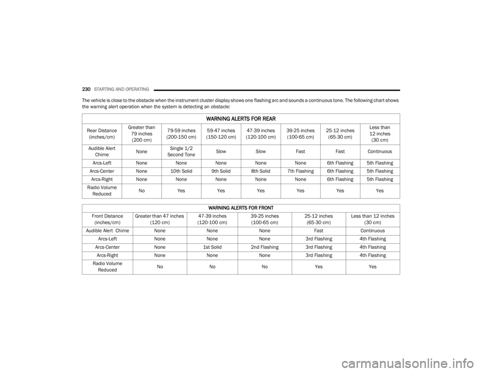
The vehicle is close to the obstacle when the instrument cluster display shows one flashing arc and sounds a continuous tone. The following chart shows
the warning alert operation when the system is detecting an obstacle:
WARNING ALERTS FOR REAR
Rear Distance
(inches/cm) Greater than
79 inches (200 cm) 79-59 inches
(200-150 cm) 59-47 inches
(150-120 cm) 47-39 inches
(120-100 cm) 39-25 inches
(100-65 cm) 25-12 inches
(65-30 cm) Less than
12 inches (30 cm)
Audible Alert Chime NoneSingle 1/2
Second Tone Slow
Slow FastFast Continuous
Arcs-Left None NoneNoneNoneNone 6th Flashing 5th Flashing
Arcs-Center None 10th Solid 9th Solid 8th Solid 7th Flashing 6th Flashing 5th Flashing Arcs-Right None NoneNoneNoneNone 6th Flashing 5th Flashing
Radio Volume Reduced No
Yes YesYesYesYesYes
WARNING ALERTS FOR FRONT
Front Distance (inches/cm) Greater than 47 inches
(120 cm) 47-39 inches
(120-100 cm) 39-25 inches
(100-65 cm) 25-12 inches
(65-30 cm) Less than 12 inches
(30 cm)
Audible Alert Chime None NoneNone FastContinuous
Arcs-Left NoneNoneNone3rd Flashing 4th Flashing
Arcs-Center None1st Solid2nd Flashing 3rd Flashing4th Flashing
Arcs-Right NoneNoneNone3rd Flashing 4th Flashing
Radio Volume Reduced No
NoNo Yes Yes
20_WD_OM_EN_USC_t.book Page 230
Page 233 of 464
STARTING AND OPERATING231
NOTE:
ParkSense will reduce the volume of the radio,
if on, when the system is sounding an audio
tone.
Front Park Assist Audible Alerts
ParkSense will turn off the Front Park Assist
audible alert (chime) after approximately three
seconds when an obstacle has been detected,
the vehicle is stationary, and brake pedal is
applied.
Adjustable Chime Volume Settings
Front and Rear chime volume settings can be
selected from the Uconnect System. Refer to
"Uconnect Settings” in “Multimedia” for further
information.
The chime volume settings include low,
medium, and high. The factory default volume
setting is medium.
ParkSense will retain its last known
configuration state through ignition cycles.
PARKSENSE WARNING DISPLAY
The ParkSense Warning screen will only be
displayed if Sound and Display is selected from
the Customer Programmable Features section
of the Uconnect System. Refer to "Uconnect Settings” in “Multimedia” for
further information.
The ParkSense Warning screen is located within
the instrument cluster display. It provides visual
warnings to indicate the distance between the
rear fascia/bumper and/or front fascia/bumper
and the detected obstacle. Refer to “Instrument
Cluster Display” in “Getting To Know Your
Instrument Panel” for further information.
ENABLING AND DISABLING PARKSENSE
ParkSense can be enabled and disabled with
the ParkSense switch.
When the ParkSense switch is pushed
to disable the system, the instrument
cluster will display the “PARKSENSE
OFF” message for approximately five
seconds. When the gear selector is moved to
REVERSE and the system is disabled, the
instrument cluster display will display the
“PARKSENSE OFF” message for as long as the
vehicle is in REVERSE.
Refer to “Instrument Cluster Display” in
“Getting To Know Your Instrument Panel” for
further information. NOTE:
When ParkSense is disabled and the gear
selector is moved to the DRIVE position, no
warning message will be displayed.
The ParkSense switch LED will be on when
ParkSense is disabled or requires service. The
ParkSense switch LED will be off when the
system is enabled. If the ParkSense switch is
pushed, and the system requires service, the
ParkSense switch LED will blink momentarily,
and then the LED will be on.OPERATION WITH A TRAILER
For vehicles equipped with an Integrated Trailer
Brake Module (ITBM), the operation of the rear
sensors is automatically deactivated when the
trailer's electric plug is inserted in the vehicle's
tow hook socket. The front system is still
functional, and the arcs will be overlaid with a
“Trailer” message. The rear sensors are
automatically reactivated when the trailer's
cable plug is removed.
5
20_WD_OM_EN_USC_t.book Page 231
Page 235 of 464
STARTING AND OPERATING233
PARKSENSE SYSTEM USAGE
P
RECAUTIONS
NOTE:
Ensure that the front and rear bumper are
free of snow, ice, mud, dirt and debris to keep
the ParkSense system operating properly.
Jackhammers, large trucks, and other vibra -
tions could affect the performance of
ParkSense.
When you turn ParkSense off, the instrument
cluster will display “PARKSENSE OFF.”
Furthermore, once you turn ParkSense off, it
remains off until you turn it on again, even if
you cycle the ignition.
When you move the gear selector to the
REVERSE position and ParkSense is turned
off, the instrument cluster will display “PARK -
SENSE OFF” for as long as the vehicle is in
REVERSE.
ParkSense, when on, will reduce the volume
of the radio when it is sounding a tone.
Clean the ParkSense sensors regularly,
taking care not to scratch or damage them.
The sensors must not be covered with ice,
snow, slush, mud, dirt or debris. Failure to do
so can result in the system not working prop -
erly. The ParkSense system might not detect
an obstacle behind or in front of the fascia/
bumper, or it could provide a false indication
that an obstacle is behind or in front of the
fascia/bumper.
Use the ParkSense switch to turn the
ParkSense system off if objects such as
bicycle carriers, trailer hitches, etc. are
placed within 12 inches (30 cm) from the
rear fascia/bumper. Failure to do so can
result in the system misinterpreting a close
object as a sensor problem, causing the
“PARKSENSE UNAVAILABLE SERVICE
REQUIRED” message to be displayed in the
instrument cluster.
ParkSense should be disabled when the lift -
gate is in the open position. An opened lift -
gate could provide a false indication that an
obstacle is behind the vehicle.
WARNING!
Drivers must be careful when backing up
even when using ParkSense. Always check
carefully behind your vehicle, look behind
you, and be sure to check for pedestrians,
animals, other vehicles, obstructions, and
blind spots before backing up. You are
responsible for safety and must continue to
pay attention to your surroundings. Failure
to do so can result in serious injury or
death.
Before using ParkSense, it is strongly
recommended that the ball mount and
hitch ball assembly is disconnected from
the vehicle when the vehicle is not used for
towing. Failure to do so can result in injury
or damage to vehicles or obstacles
because the hitch ball will be much closer
to the obstacle than the rear fascia when
the loudspeaker sounds the continuous
tone. Also, the sensors could detect the ball
mount and hitch ball assembly, depending
on its size and shape, giving a false indica -
tion that an obstacle is behind the vehicle.5
20_WD_OM_EN_USC_t.book Page 233
Page 239 of 464
STARTING AND OPERATING237
CHANGING LANESENSE STATUS
The LaneSense system has settings to adjust
the intensity of the torque warning and the
warning zone sensitivity (early/late) that you
can configure through the Uconnect system
screen. Refer to “Uconnect Settings” in
“Multimedia” for further information.
NOTE:
When enabled the system operates above
37 mph (60 km/h) and below 112 mph
(180 km/h).
Use of the turn signal suppresses the
warnings.
The system will not apply torque to the
steering wheel whenever a safety system
engages (Anti-Lock Brakes, Traction Control
System, Electronic Stability Control, Forward
Collision Warning, etc.).
PARKVIEW REAR BACK UP CAMERA
Your vehicle is equipped with the ParkView Rear
Back Up Camera that allows you to see an
on-screen image of the rear surroundings of
your vehicle whenever the gear selector is put
into REVERSE. The image will be displayed on
the Navigation/Multimedia radio display screen
along with a caution note to “check entire
surroundings” across the top of the screen.
After five seconds this note will disappear. The
ParkView camera is located on the rear of the
vehicle above the rear license plate.
When the vehicle is shifted out of REVERSE
(with camera delay turned off), the rear camera
mode is exited and the navigation or audio
screen appears again.
Manual Activation Of The Backup Camera
1. Press the “Controls” button located on the
bottom of the Uconnect display.
2. Press the “Backup Camera” button to turn the Rear View Camera system on. NOTE:
The ParkView Rear Back Up Camera has
programmable modes of operation that may be
selected through the Uconnect System.
Refer to “Uconnect Settings” in “Multimedia”
for further information.
When the vehicle is shifted out of REVERSE
(with camera delay turned off), the rear camera
mode is exited and the previous screen appears
again. When the vehicle is shifted out of
REVERSE (with camera delay turned on), the
camera image will continue to be displayed for
up to ten seconds, unless the vehicle speed
exceeds 8 mph (13 km/h), the vehicle is shifted
into PARK, the vehicle’s ignition is placed in the
OFF position, or the user presses image defeat
“X” to exit out of the camera video display.
When enabled, active guidelines are overlaid on
the image to illustrate the width of the vehicle
and its projected backup path based on the
steering wheel position. A dashed center line
overlay indicates the center of the vehicle to
assist with parking or aligning to a hitch/
receiver. Different colored zones indicate the
distance to the rear of the vehicle.
5
20_WD_OM_EN_USC_t.book Page 237
Page 265 of 464
IN CASE OF EMERGENCY263
(Continued)
NOTE:
Your vehicle may be transmitting data as
authorized by the subscriber.
Once a connection is made between the
vehicle’s SOS Call system and the SOS oper -
ator, the SOS operator may be able to open a
voice connection with the vehicle to deter -
mine if additional assistance is needed. Once
the SOS operator opens a voice connection
with the vehicle’s SOS Call system, the oper -
ator should be able to speak with you or other
vehicle occupants and hear sounds occurring
in the vehicle. The vehicle’s SOS Call system will attempt to
remain connected with the SOS operator
until the SOS operator terminates the
connection.
5. The SOS operator may attempt to contact appropriate emergency responders and
provide them with important vehicle
information and GPS coordinates.
WARNING!
ALWAYS obey traffic laws and pay attention to
the road. ALWAYS drive safely with your hands
on the steering wheel. You have full
responsibility and assume all risks related to
the use of the features and applications in
this vehicle. Only use the features and
applications when it is safe to do so. Failure
to do so may result in an accident involving
serious injury or death.
WARNING!
If anyone in the vehicle could be in danger
(e.g., fire or smoke is visible, dangerous
road conditions or location), do not wait for
voice contact from an Emergency Services
Agent. All occupants should exit the vehicle
immediately and move to a safe location.
Never place anything on or near the
vehicle’s operable network and GPS
antennas. You could prevent operable
network and GPS signal reception, which
can prevent your vehicle from placing an
emergency call. An operable network and
GPS signal reception is required for the SOS
Call system to function properly.
The SOS Call system is embedded into the
vehicle’s electrical system. Do not add
aftermarket electrical equipment to the
vehicle’s electrical system. This may
prevent your vehicle from sending a signal
to initiate an emergency call. To avoid inter -
ference that can cause the SOS Call system
to fail, never add aftermarket equipment
(e.g., two-way mobile radio, CB radio, data
recorder, etc.) to your vehicle’s electrical
system or modify the antennas on your
vehicle. IF YOUR VEHICLE LOSES BATTERY
POWER FOR ANY REASON (INCLUDING
DURING OR AFTER AN ACCIDENT), THE
UCONNECT FEATURES, APPS AND
SERVICES, AMONG OTHERS, WILL NOT
OPERATE.
Modifications to any part of the SOS Call
system could cause the air bag system to
fail when you need it. You could be injured
if the air bag system is not there to help
protect you.
WARNING! (Continued)
6
20_WD_OM_EN_USC_t.book Page 263
Page 267 of 464
IN CASE OF EMERGENCY265
NOTE:
Your vehicle may be transmitting data as
authorized by the subscriber.
Never place anything on or near the vehicle’s
LTE (voice/data) or 4G (data) and GPS
antennas. You could prevent LTE (voice/
data) or 4G (data) and GPS signal reception,
which can prevent your vehicle from placing
an emergency call. An operable LTE (voice/
data) or 4G (data) network connection and a
GPS signal is required for the SOS Call
system to function properly.
NOTE:
Changes or modifications not expressly
approved by the party responsible for compli -
ance could void the user's authority to operate
the equipment.
GENERAL INFORMATION
The following regulatory statement applies to all
Radio Frequency (RF) devices equipped in this
vehicle:
This device complies with Part 15 of the FCC
Rules and with Innovation, Science and
Economic Development Canada license-exempt
RSS standard(s). Operation is subject to the
following two conditions:
1. This device may not cause harmful interference, and
2. This device must accept any interference received, including interference that may
cause undesired operation. Le présent appareil est conforme aux CNR
d`Innovation, Science and Economic
Development applicables aux appareils radio
exempts de licence. L'exploitation est autorisée
aux deux conditions suivantes:
1. l'appareil ne doit pas produire de
brouillage, et
2. l'utilisateur de l'appareil doit accepter tout brouillage radioélectrique subi, même si le
brouillage est susceptible d'en compro -
mettre le fonctionnement.
La operación de este equipo está sujeta a las
siguientes dos condiciones:
1. es posible que este equipo o dispositivo no cause interferencia perjudicial y
2. este equipo o dispositivo debe aceptar cualquier interferencia, incluyendo la que
pueda causar su operación no deseada.
NOTE:
Changes or modifications not expressly
approved by the party responsible for compli -
ance could void the user’s authority to operate
the equipment.
CAUTION!
To avoid damage to the mirror during
cleaning, never spray any cleaning solution
directly onto the mirror. Apply the solution
onto a clean cloth and wipe the mirror clean.
6
20_WD_OM_EN_USC_t.book Page 265