radio DODGE DURANGO 2020 User Guide
[x] Cancel search | Manufacturer: DODGE, Model Year: 2020, Model line: DURANGO, Model: DODGE DURANGO 2020Pages: 464, PDF Size: 22.14 MB
Page 30 of 464
28GETTING TO KNOW YOUR VEHICLE
NOTE:
If “Unlock All Doors 1st Press” is programmed in
Uconnect Settings, all doors will unlock when
you push the button on the liftgate. If "Unlock
Driver Door 1st Press" is programmed in Ucon -
nect Settings, the liftgate will unlock when you
push the button on the liftgate. For further infor -
mation, refer to “Uconnect Settings” in “Multi -
media”.
To Lock The Vehicle’s Doors
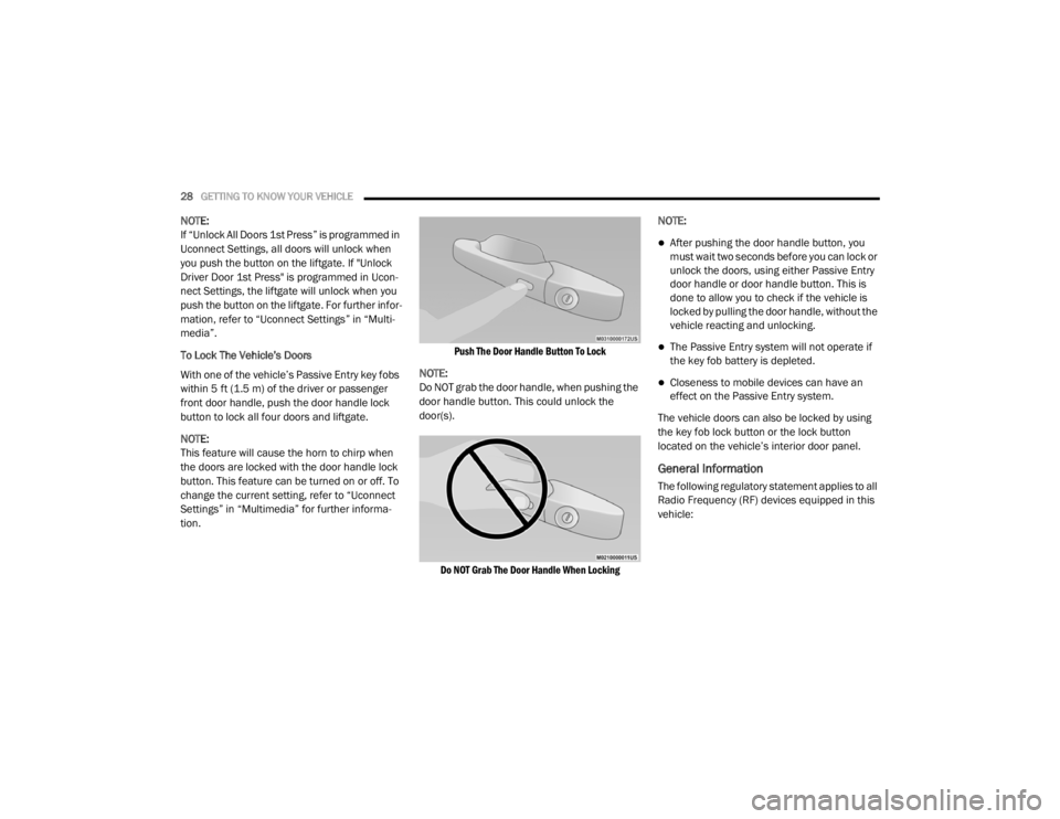
With one of the vehicle’s Passive Entry key fobs
within 5 ft (1.5 m) of the driver or passenger
front door handle, push the door handle lock
button to lock all four doors and liftgate.
NOTE:
This feature will cause the horn to chirp when
the doors are locked with the door handle lock
button. This feature can be turned on or off. To
change the current setting, refer to “Uconnect
Settings” in “Multimedia” for further informa -
tion.
Push The Door Handle Button To Lock
NOTE:
Do NOT grab the door handle, when pushing the
door handle button. This could unlock the
door(s).
Do NOT Grab The Door Handle When Locking
NOTE:
After pushing the door handle button, you
must wait two seconds before you can lock or
unlock the doors, using either Passive Entry
door handle or door handle button. This is
done to allow you to check if the vehicle is
locked by pulling the door handle, without the
vehicle reacting and unlocking.
The Passive Entry system will not operate if
the key fob battery is depleted.
Closeness to mobile devices can have an
effect on the Passive Entry system.
The vehicle doors can also be locked by using
the key fob lock button or the lock button
located on the vehicle’s interior door panel.
General Information
The following regulatory statement applies to all
Radio Frequency (RF) devices equipped in this
vehicle:
20_WD_OM_EN_USC_t.book Page 28
Page 31 of 464

GETTING TO KNOW YOUR VEHICLE29
This device complies with Part 15 of the FCC
Rules and with Innovation, Science and
Economic Development Canada license-exempt
RSS standard(s). Operation is subject to the
following two conditions:
1. This device may not cause harmful
interference, and
2. This device must accept any interference received, including interference that may
cause undesired operation.
Le présent appareil est conforme aux CNR
d`Innovation, Science and Economic
Development applicables aux appareils radio
exempts de licence. L'exploitation est autorisée
aux deux conditions suivantes:
1. l'appareil ne doit pas produire de brouillage, et
2. l'utilisateur de l'appareil doit accepter tout brouillage radioélectrique subi, même si le
brouillage est susceptible d'en compro -
mettre le fonctionnement. La operación de este equipo está sujeta a las
siguientes dos condiciones:
1. es posible que este equipo o dispositivo no
cause interferencia perjudicial y
2. este equipo o dispositivo debe aceptar cualquier interferencia, incluyendo la que
pueda causar su operación no deseada.
NOTE:
Changes or modifications not expressly
approved by the party responsible for compli -
ance could void the user’s authority to operate
the equipment.
AUTOMATIC UNLOCK ON EXIT FEATURE
— I
F EQUIPPED
If Auto Unlock is enabled, this feature will
unlock all the doors when any door is opened if
the vehicle is in PARK.
Refer to “Uconnect Settings” in “Multimedia”
for further information.
AUTOMATIC DOOR LOCKS — IF
E
QUIPPED
When enabled, the door locks will lock
automatically when the vehicle’s speed
exceeds 15 mph (24 km/h). Auto door lock
feature is enabled/disabled in the Uconnect
Settings sections in the radio. Refer to
“Uconnect Settings” in “Multimedia” for further
information.
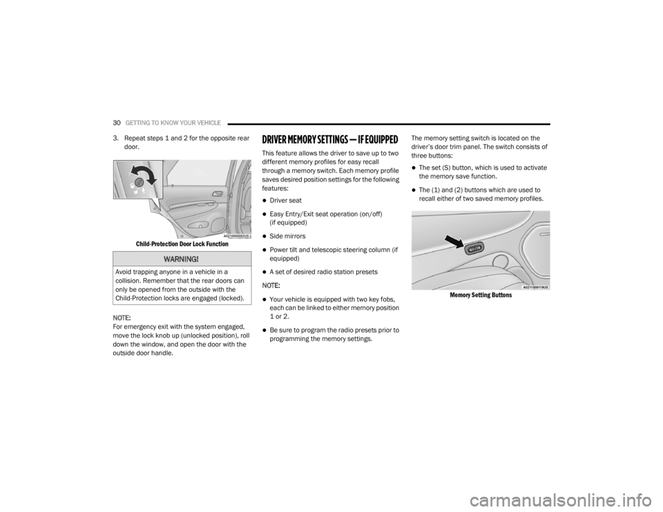
CHILD-PROTECTION DOOR LOCK
S
YSTEM — REAR DOORS
To provide a safer environment for small
children riding in the rear seats, the rear doors
are equipped with Child-Protection Door Lock
system.
To Engage Or Disengage The Child Protection
Door Lock System
1. Open the rear door.
2. Insert the tip of the emergency key into the
lock and rotate to the lock or unlock
position.
2
20_WD_OM_EN_USC_t.book Page 29
Page 32 of 464
30GETTING TO KNOW YOUR VEHICLE
3. Repeat steps 1 and 2 for the opposite rear
door.
Child-Protection Door Lock Function
NOTE:
For emergency exit with the system engaged,
move the lock knob up (unlocked position), roll
down the window, and open the door with the
outside door handle.DRIVER MEMORY SETTINGS — IF EQUIPPED
This feature allows the driver to save up to two
different memory profiles for easy recall
through a memory switch. Each memory profile
saves desired position settings for the following
features:
Driver seat
Easy Entry/Exit seat operation (on/off)
(if equipped)
Side mirrors
Power tilt and telescopic steering column (if
equipped)
A set of desired radio station presets
NOTE:
Your vehicle is equipped with two key fobs,
each can be linked to either memory position
1 or 2.
Be sure to program the radio presets prior to
programming the memory settings. The memory setting switch is located on the
driver’s door trim panel. The switch consists of
three buttons:
The set (S) button, which is used to activate
the memory save function.
The (1) and (2) buttons which are used to
recall either of two saved memory profiles.
Memory Setting Buttons
WARNING!
Avoid trapping anyone in a vehicle in a
collision. Remember that the rear doors can
only be opened from the outside with the
Child-Protection locks are engaged (locked).
20_WD_OM_EN_USC_t.book Page 30
Page 33 of 464

GETTING TO KNOW YOUR VEHICLE31
PROGRAMMING THE MEMORY FEATURE
To create a new memory profile, perform the
following:
1. Place the vehicle’s ignition in the ON/RUN
position (do not start the engine).
2. Adjust all memory profile settings to desired preferences (i.e., seat, side mirror, power tilt
and telescopic steering column [if
equipped], and radio station presets).
3. Push the set (S) button on the memory switch, and then push the desired memory
button (1 or 2) within five seconds. The
instrument cluster display will display which
memory position has been set.
NOTE:
Memory profiles can be set without the vehicle
in PARK, but the vehicle must be in PARK to
recall a memory profile.
LINKING AND UNLINKING THE REMOTE
K
EYLESS ENTRY KEY FOB TO MEMORY
Your key fobs can be programmed to recall one
of two saved memory profiles by pushing the
unlock button on the key fob.
NOTE:
Before programming your key fobs you must
select the “Memory Linked To Fob” feature
through the Uconnect system settings. Refer to
“Uconnect Settings” in “Multimedia” for further
information.
To program your key fobs, perform the following:
1. Place the vehicle’s ignition in the OFF
position.
2. Select a desired memory profile, 1 or 2.
3. Once the profile has been recalled, push and release the set (S) button on the
memory switch. Then, within five seconds,
push and release button (1) or (2)
accordingly. “Memory Profile Set” (1 or 2)
will display in the instrument cluster display.
4. Push and release the lock button on the key fob within 10 seconds. NOTE:
Your key fobs can be unlinked from your
memory settings by pushing the set (S) button,
and within 10 seconds, followed by pushing the
unlock button on the key fob.
MEMORY POSITION RECALL
NOTE:
If a recall is attempted when the vehicle is not in
PARK, a message will be displayed in the instru
-
ment cluster display.
To recall the memory settings for driver one or
two, push the desired memory button (1 or 2) or
the unlock button on the key fob linked to the
desired memory position.
A recall can be canceled by pushing any of the
memory buttons during a recall (S, 1, or 2), or by
pushing any of the seat adjustment switches.
When a recall is canceled, the driver's seat and
telescopic steering column (if equipped) will
stop moving. A delay of one second will occur
before another recall can be selected.
2
20_WD_OM_EN_USC_t.book Page 31
Page 42 of 464
40GETTING TO KNOW YOUR VEHICLE
When you place the vehicle’s ignition in the
OFF position, the driver seat will move about
2.4 inches (60 mm) rearward if the driver
seat position is greater than or equal to
2.7 inches (67.7 mm) forward of the rear stop. The seat will return to its previously set
position when you place the vehicle’s ignition
in the ACC or RUN position.
The Easy Entry/Easy Exit feature is disabled
when the driver seat position is less than 0.9
of an inch (22.7 mm) forward of the rear
stop. At this position, there is no benefit to
the driver by moving the seat for Easy Exit or
Easy Entry.
When enabled in Uconnect Settings, Easy Entry
and Easy Exit positions are stored in each
memory setting profile. Refer to “Driver Memory
Settings — If Equipped” in this chapter for
further information.
NOTE:
The Easy Entry/Exit feature is not enabled when
the vehicle is delivered from the factory. The
Easy Entry/Exit feature is enabled (or later
disabled) through the programmable features
in the Uconnect system. Refer to “Uconnect
Settings” in “Multimedia” for further
information.
HEATED SEATS — IF EQUIPPED
On some models, the front and rear seats may
be equipped with heaters located in the seat
cushions and seatbacks.
Front Heated Seats
The front heated seat control buttons are
located within the climate or controls screen of
the touchscreen. You can choose from HI, LO, or OFF heat
settings. The indicator arrows on the
touchscreen buttons indicate the level of heat
in use. Two indicator arrows will illuminate for
HI, and one for LO. Turning the heating
elements off will return the user to the radio
screen.
Press the heated seat button once to turn
the HI setting on.
Press the heated seat button a second
time to turn the LO setting on.
Press the heated seat button a third time
to turn the heating elements off.
NOTE:
Once a heat setting is selected, heat will be
felt within two to five minutes.
The engine must be running for the heated
seats to operate.
The level of heat selected will stay on until
the operator changes it.
WARNING!
Persons who are unable to feel pain to the
skin because of advanced age, chronic
illness, diabetes, spinal cord injury, medica -
tion, alcohol use, exhaustion or other phys -
ical condition must exercise care when
using the seat heater. It may cause burns
even at low temperatures, especially if
used for long periods of time.
Do not place anything on the seat or seat -
back that insulates against heat, such as a
blanket or cushion. This may cause the seat
heater to overheat. Sitting in a seat that has
been overheated could cause serious
burns due to the increased surface
temperature of the seat.
20_WD_OM_EN_USC_t.book Page 40
Page 57 of 464
GETTING TO KNOW YOUR VEHICLE55
When a door is open and the interior lights are
on, rotating the dimmer control all the way
down, to the (O) off detent, will cause all the
interior lights to go out. This is also known as
the “Party” mode because it allows the doors to
stay open for extended periods of time without
discharging the vehicle’s battery.
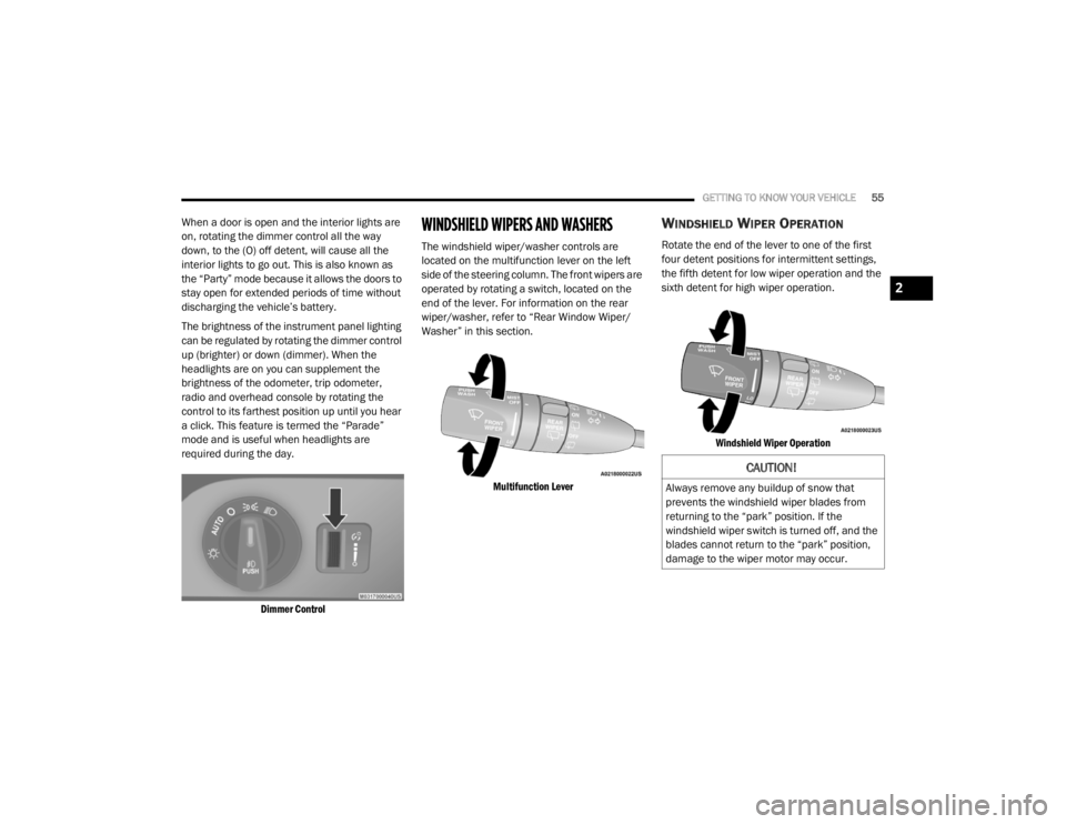
The brightness of the instrument panel lighting
can be regulated by rotating the dimmer control
up (brighter) or down (dimmer). When the
headlights are on you can supplement the
brightness of the odometer, trip odometer,
radio and overhead console by rotating the
control to its farthest position up until you hear
a click. This feature is termed the “Parade”
mode and is useful when headlights are
required during the day.
Dimmer Control
WINDSHIELD WIPERS AND WASHERS
The windshield wiper/washer controls are
located on the multifunction lever on the left
side of the steering column. The front wipers are
operated by rotating a switch, located on the
end of the lever. For information on the rear
wiper/washer, refer to “Rear Window Wiper/
Washer” in this section.
Multifunction Lever
WINDSHIELD WIPER OPERATION
Rotate the end of the lever to one of the first
four detent positions for intermittent settings,
the fifth detent for low wiper operation and the
sixth detent for high wiper operation.
Windshield Wiper Operation
CAUTION!
Always remove any buildup of snow that
prevents the windshield wiper blades from
returning to the “park” position. If the
windshield wiper switch is turned off, and the
blades cannot return to the “park” position,
damage to the wiper motor may occur.
2
20_WD_OM_EN_USC_t.book Page 55
Page 60 of 464
58GETTING TO KNOW YOUR VEHICLE
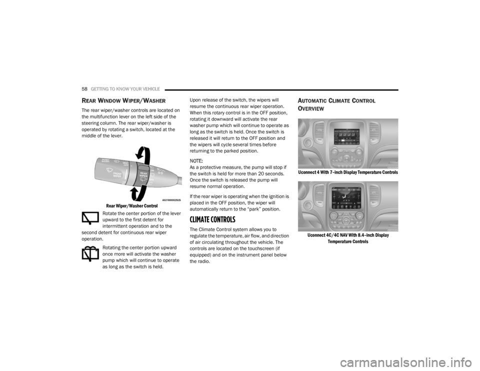
REAR WINDOW WIPER/WASHER
The rear wiper/washer controls are located on
the multifunction lever on the left side of the
steering column. The rear wiper/washer is
operated by rotating a switch, located at the
middle of the lever.
Rear Wiper/Washer Control
Rotate the center portion of the lever
upward to the first detent for
intermittent operation and to the
second detent for continuous rear wiper
operation.
Rotating the center portion upward
once more will activate the washer
pump which will continue to operate
as long as the switch is held. Upon release of the switch, the wipers will
resume the continuous rear wiper operation.
When this rotary control is in the OFF position,
rotating it downward will activate the rear
washer pump which will continue to operate as
long as the switch is held. Once the switch is
released it will return to the OFF position and
the wipers will cycle several times before
returning to the parked position.
NOTE:
As a protective measure, the pump will stop if
the switch is held for more than 20 seconds.
Once the switch is released the pump will
resume normal operation.
If the rear wiper is operating when the ignition is
placed in the OFF position, the wiper will
automatically return to the “park” position.
CLIMATE CONTROLS
The Climate Control system allows you to
regulate the temperature, air flow, and direction
of air circulating throughout the vehicle. The
controls are located on the touchscreen (if
equipped) and on the instrument panel below
the radio.
AUTOMATIC CLIMATE CONTROL
O
VERVIEW
Uconnect 4 With 7–inch Display Temperature Controls
Uconnect 4C/4C NAV With 8.4–inch Display Temperature Controls
20_WD_OM_EN_USC_t.book Page 58
Page 81 of 464
GETTING TO KNOW YOUR VEHICLE79
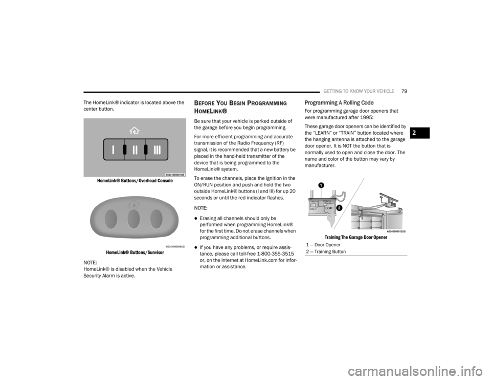
The HomeLink® indicator is located above the
center button.
HomeLink® Buttons/Overhead ConsoleHomeLink® Buttons/Sunvisor
NOTE:
HomeLink® is disabled when the Vehicle
Security Alarm is active.BEFORE YOU BEGIN PROGRAMMING
H
OMELINK®
Be sure that your vehicle is parked outside of
the garage before you begin programming.
For more efficient programming and accurate
transmission of the Radio Frequency (RF)
signal, it is recommended that a new battery be
placed in the hand-held transmitter of the
device that is being programmed to the
HomeLink® system.
To erase the channels, place the ignition in the
ON/RUN position and push and hold the two
outside HomeLink® buttons (I and III) for up 20
seconds or until the red indicator flashes.
NOTE:
Erasing all channels should only be
performed when programming HomeLink®
for the first time. Do not erase channels when
programming additional buttons.
If you have any problems, or require assis -
tance, please call toll-free 1-800-355-3515
or, on the Internet at HomeLink.com for infor -
mation or assistance.
Programming A Rolling Code
For programming garage door openers that
were manufactured after 1995:
These garage door openers can be identified by
the “LEARN” or “TRAIN” button located where
the hanging antenna is attached to the garage
door opener. It is NOT the button that is
normally used to open and close the door. The
name and color of the button may vary by
manufacturer.
Training The Garage Door Opener
1 — Door Opener
2 — Training Button
2
20_WD_OM_EN_USC_t.book Page 79
Page 83 of 464

GETTING TO KNOW YOUR VEHICLE81
Release both buttons after the indicator
light changes from slow to rapid.
5. Push and hold the programmed HomeLink® button and observe the
indicator light.
If the indicator light stays on constantly,
programming is complete and the garage
door/device should activate when the
HomeLink® button is pushed.
To program the two remaining Home -
Link® buttons, repeat each step for each
remaining button. DO NOT erase the
channels.
CANADIAN/GATE OPERATOR
P
ROGRAMMING
For programming transmitters in Canada/
United States that require the transmitter
signals to “time-out” after several seconds of
transmission:
Canadian Radio Frequency (RF) laws require
transmitter signals to time-out (or quit) after
several seconds of transmission, which may not
be long enough for HomeLink® to pick up the
signal during programming. Similar to this Canadian law, some U.S. gate
operators are designed to time-out in the same
manner.
It may be helpful to unplug the device during the
cycling process to prevent possible overheating
of the garage door or gate motor.
1. Place the ignition in the ON/RUN position.
NOTE:
For vehicles equipped with Keyless Enter-N-Go,
place the ignition in the RUN position with the
engine on. Make sure while programming
HomeLink® with the engine on that your vehicle
is outside of your garage, or that the garage
door remains open at all times.
2. Place the hand-held transmitter 1 to
3 inches (3 to 8 cm) away from the
HomeLink® button you wish to program
while keeping the HomeLink® indicator
light in view.
3. Continue to push and hold the HomeLink® button while you push and release (“cycle”)
your hand-held transmitter every two
seconds until HomeLink® has successfully
accepted the frequency signal. The indicator light will flash slowly and then
rapidly when fully trained.
4. Watch for the HomeLink® indicator to change flash rates. When it changes, it is
programmed. It may take up to 30 seconds
or longer in rare cases. The garage door
may open and close while you are
programming.
5. Push and hold the programmed HomeLink® button and observe the
indicator light.
NOTE:
If the indicator light stays on constantly,
programming is complete and the garage
door/device should activate when the Home -
Link® button is pushed.
To program the two remaining HomeLink®
buttons, repeat each step for each remaining
button. DO NOT erase the channels.
If you unplugged the garage door opener/
device for programming, plug it back in at this
time.
2
20_WD_OM_EN_USC_t.book Page 81
Page 85 of 464
GETTING TO KNOW YOUR VEHICLE83
GENERAL INFORMATION
The following regulatory statement applies to all
Radio Frequency (RF) devices equipped in this
vehicle:
This device complies with Part 15 of the FCC
Rules and with Innovation, Science and
Economic Development Canada license-exempt
RSS standard(s). Operation is subject to the
following two conditions:
1. This device may not cause harmful
interference, and
2. This device must accept any interference received, including interference that may
cause undesired operation.
Le présent appareil est conforme aux CNR
d`Innovation, Science and Economic
Development applicables aux appareils radio
exempts de licence. L'exploitation est autorisée aux deux conditions
suivantes:
1. l'appareil ne doit pas produire de
brouillage, et
2. l'utilisateur de l'appareil doit accepter tout brouillage radioélectrique subi, même si le
brouillage est susceptible d'en compro -
mettre le fonctionnement.
La operación de este equipo está sujeta a las
siguientes dos condiciones:
1. es posible que este equipo o dispositivo no cause interferencia perjudicial y
2. este equipo o dispositivo debe aceptar cualquier interferencia, incluyendo la que
pueda causar su operación no deseada.
NOTE:
Changes or modifications not expressly
approved by the party responsible for compli -
ance could void the user’s authority to operate
the equipment.
INTERNAL EQUIPMENT
STORAGE
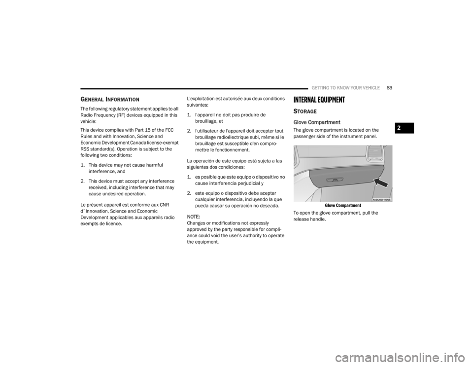
Glove Compartment
The glove compartment is located on the
passenger side of the instrument panel.
Glove Compartment
To open the glove compartment, pull the
release handle.2
20_WD_OM_EN_USC_t.book Page 83