ECO mode DODGE DURANGO 2020 Service Manual
[x] Cancel search | Manufacturer: DODGE, Model Year: 2020, Model line: DURANGO, Model: DODGE DURANGO 2020Pages: 464, PDF Size: 22.14 MB
Page 155 of 464
SAFETY153
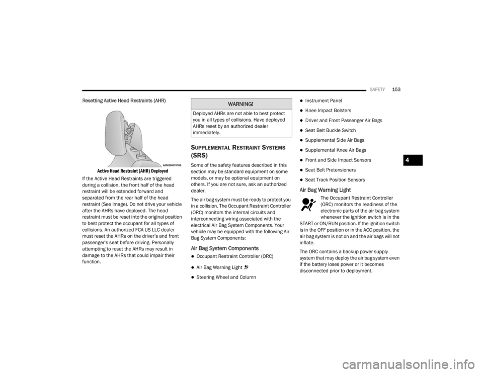
Resetting Active Head Restraints (AHR)
Active Head Restraint (AHR) Deployed
If the Active Head Restraints are triggered
during a collision, the front half of the head
restraint will be extended forward and
separated from the rear half of the head
restraint (See Image). Do not drive your vehicle
after the AHRs have deployed. The head
restraint must be reset into the original position
to best protect the occupant for all types of
collisions. An authorized FCA US LLC dealer
must reset the AHRs on the driver’s and front
passenger’s seat before driving. Personally
attempting to reset the AHRs may result in
damage to the AHRs that could impair their
function.
SUPPLEMENTAL RESTRAINT SYSTEMS
(SRS)
Some of the safety features described in this
section may be standard equipment on some
models, or may be optional equipment on
others. If you are not sure, ask an authorized
dealer.
The air bag system must be ready to protect you
in a collision. The Occupant Restraint Controller
(ORC) monitors the internal circuits and
interconnecting wiring associated with the
electrical Air Bag System Components. Your
vehicle may be equipped with the following Air
Bag System Components:
Air Bag System Components
Occupant Restraint Controller (ORC)
Air Bag Warning Light
Steering Wheel and Column
Instrument Panel
Knee Impact Bolsters
Driver and Front Passenger Air Bags
Seat Belt Buckle Switch
Supplemental Side Air Bags
Supplemental Knee Air Bags
Front and Side Impact Sensors
Seat Belt Pretensioners
Seat Track Position Sensors
Air Bag Warning Light
The Occupant Restraint Controller
(ORC) monitors the readiness of the
electronic parts of the air bag system
whenever the ignition switch is in the
START or ON/RUN position. If the ignition switch
is in the OFF position or in the ACC position, the
air bag system is not on and the air bags will not
inflate.
The ORC contains a backup power supply
system that may deploy the air bag system even
if the battery loses power or it becomes
disconnected prior to deployment.
WARNING!
Deployed AHRs are not able to best protect
you in all types of collisions. Have deployed
AHRs reset by an authorized dealer
immediately.
4
20_WD_OM_EN_USC_t.book Page 153
Page 177 of 464
SAFETY175
Installing Child Restraints Using The
Vehicle Seat Belt
Child restraint systems are designed to be
secured in vehicle seats by lap belts or the lap
belt portion of a lap/shoulder belt.
The seat belts in the passenger seating
positions are equipped with a Switchable
Automatic Locking Retractor (ALR) that is
designed to keep the lap portion of the seat belt
tight around the child restraint so that it is not
necessary to use a locking clip. The ALR
retractor can be “switched” into a locked mode
by pulling all of the webbing out of the retractor
and then letting the webbing retract back into
the retractor. If it is locked, the ALR will make a
clicking noise while the webbing is pulled back
into the retractor. Refer to the “Automatic Locking Mode”
description in “Switchable Automatic Locking
Retractors (ALR)” under “Occupant Restraint
Systems” for additional information on ALR.
Please see the table below and the following
sections for more information.
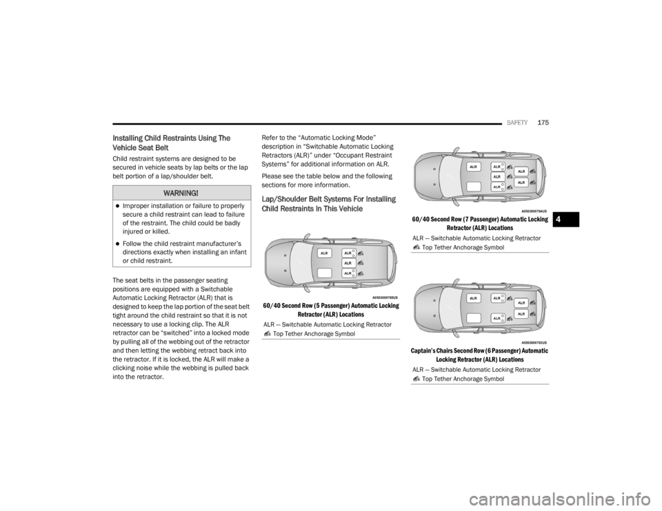
Lap/Shoulder Belt Systems For Installing
Child Restraints In This Vehicle
60/40 Second Row (5 Passenger) Automatic Locking
Retractor (ALR) Locations 60/40 Second Row (7 Passenger) Automatic Locking
Retractor (ALR) Locations
Captain’s Chairs Second Row (6 Passenger) Automatic Locking Retractor (ALR) Locations
WARNING!
Improper installation or failure to properly
secure a child restraint can lead to failure
of the restraint. The child could be badly
injured or killed.
Follow the child restraint manufacturer’s
directions exactly when installing an infant
or child restraint.
ALR — Switchable Automatic Locking Retractor
Top Tether Anchorage Symbol
ALR — Switchable Automatic Locking Retractor Top Tether Anchorage Symbol
ALR — Switchable Automatic Locking Retractor Top Tether Anchorage Symbol
4
20_WD_OM_EN_USC_t.book Page 175
Page 179 of 464
SAFETY177
Installing A Child Restraint With A
Switchable Automatic Locking Retractor
(ALR):
Child restraint systems are designed to be
secured in vehicle seats by lap belts or the lap
belt portion of a lap/shoulder belt.
1. Place the child seat in the center of the
seating position. For some second row
seats, you may need to recline the seat
and/or raise the head restraint (if
adjustable) to get a better fit. If the rear
seat can be moved forward and rearward
in the vehicle, you may wish to move it to its
rear-most position to make room for the
child seat. You may also move the front
seat forward to allow more room for the
child seat.
2. Pull enough of the seat belt webbing from
the retractor to pass it through the belt path
of the child restraint. Do not twist the belt
webbing in the belt path.
3. Slide the latch plate into the buckle until you hear a “click.”
4. Pull on the webbing to make the lap portion tight against the child seat.
5. To lock the seat belt, pull down on the shoulder part of the belt until you have
pulled all the seat belt webbing out of the
retractor. Then, allow the webbing to retract
back into the retractor. As the webbing
retracts, you will hear a clicking sound. This
means the seat belt is now in the Automatic
Locking mode.
6. Try to pull the webbing out of the retractor. If it is locked, you should not be able to pull
out any webbing. If the retractor is not
locked, repeat step 5. 7. Finally, pull up on any excess webbing to
tighten the lap portion around the child
restraint while you push the child restraint
rearward and downward into the vehicle
seat.
8. If the child restraint has a top tether strap and the seating position has a top tether
anchorage, connect the tether strap to the
anchorage and tighten the tether strap. See
the section “Installing Child Restraints
Using the Top Tether Anchorage” for
directions to attach a tether anchor.
9. Test that the child restraint is installed tightly by pulling back and forth on the child
seat at the belt path. It should not move
more than 1 inch (25.4 mm) in any
direction.
Any seat belt system will loosen with time, so
check the belt occasionally, and pull it tight if
necessary.
WARNING!
Improper installation or failure to properly
secure a child restraint can lead to failure
of the restraint. The child could be badly
injured or killed.
Follow the child restraint manufacturer’s
directions exactly when installing an infant
or child restraint.
4
20_WD_OM_EN_USC_t.book Page 177
Page 183 of 464

SAFETY181
The best protection against carbon monoxide
entry into the vehicle body is a properly
maintained engine exhaust system.
Whenever a change is noticed in the sound of
the exhaust system, when exhaust fumes can
be detected inside the vehicle, or when the
underside or rear of the vehicle is damaged,
have a competent mechanic inspect the
complete exhaust system and adjacent body
areas for broken, damaged, deteriorated, or
mispositioned parts. Open seams or loose
connections could permit exhaust fumes to
seep into the passenger compartment. In
addition, inspect the exhaust system each time
the vehicle is raised for lubrication or oil
change. Replace as required.
SAFETY CHECKS YOU SHOULD MAKE
I
NSIDE THE VEHICLE
Seat Belts
Inspect the seat belt system periodically,
checking for cuts, frays, and loose parts.
Damaged parts must be replaced immediately.
Do not disassemble or modify the system.
Front seat belt assemblies must be replaced
after a collision. Rear seat belt assemblies must
be replaced after a collision if they have been
damaged (i.e., bent retractor, torn webbing,
etc.). If there is any question regarding seat belt
or retractor condition, replace the seat belt.
Air Bag Warning Light
The Air Bag warning light will turn on for four
to eight seconds as a bulb check when the
ignition switch is first turned to ON/RUN. If the
light is either not on during starting, stays on, or
turns on while driving, have the system
inspected at an authorized dealer as soon as
possible. After the bulb check, this light will
illuminate with a single chime when a fault with
the Air Bag System has been detected. It will
stay on until the fault is removed. If the light comes on intermittently or remains
on while driving, have an authorized dealer
service the vehicle immediately.
Refer to “Occupant Restraint Systems” in this
section for further information.
Defroster
Check operation by selecting the defrost mode
and place the blower control on high speed. You
should be able to feel the air directed against
the windshield. See an authorized dealer for
service if your defroster is inoperable.
Floor Mat Safety Information
Always use floor mats designed to fit your
vehicle. Only use a floor mat that does not
interfere with the operation of the accelerator,
brake or clutch pedals. Only use a floor mat that
is securely attached using the floor mat
fasteners so it cannot slip out of position and
interfere with the accelerator, brake or clutch
pedals or impair safe operation of your vehicle
in other ways.
If it is necessary to sit in a parked vehicle
with the engine running, adjust your
heating or cooling controls to force outside
air into the vehicle. Set the blower at high
speed.
WARNING!
(Continued)
4
20_WD_OM_EN_USC_t.book Page 181
Page 184 of 464
182SAFETY
(Continued)
(Continued)
WARNING!
An improperly attached, damaged, folded, or
stacked floor mat, or damaged floor mat
fasteners may cause your floor mat to
interfere with the accelerator, brake, or clutch
pedals and cause a loss of vehicle control. To
prevent SERIOUS INJURY or DEATH:
ALWAYS securely attach your floor mat
using the floor mat fasteners. DO NOT
install your floor mat upside down or turn
your floor mat over. Lightly pull to confirm
mat is secured using the floor mat
fasteners on a regular basis.
ALWAYS REMOVE THE EXISTING FLOOR
MAT FROM THE VEHICLE before
installing any other floor mat. NEVER install
or stack an additional floor mat on top of an
existing floor mat.
ONLY install floor mats designed to fit your
vehicle. NEVER install a floor mat that
cannot be properly attached and secured to
your vehicle. If a floor mat needs to be
replaced, only use a FCA approved floor
mat for the specific make, model, and year
of your vehicle.
ONLY use the driver’s side floor mat on the
driver’s side floor area. To check for inter
-
ference, with the vehicle properly parked
with the engine off, fully depress the accel -
erator, the brake, and the clutch pedal (if
present) to check for interference. If your
floor mat interferes with the operation of
any pedal, or is not secure to the floor,
remove the floor mat from the vehicle and
place the floor mat in your trunk.
ONLY use the passenger’s side floor mat on
the passenger’s side floor area.
ALWAYS make sure objects cannot fall or
slide into the driver’s side floor area when
the vehicle is moving. Objects can become
trapped under accelerator, brake, or clutch
pedals and could cause a loss of vehicle
control.
WARNING! (Continued)
NEVER place any objects under the floor
mat (e.g., towels, keys, etc.). These objects
could change the position of the floor mat
and may cause interference with the accel -
erator, brake, or clutch pedals.
If the vehicle carpet has been removed and
re-installed, always properly attach carpet
to the floor and check the floor mat
fasteners are secure to the vehicle carpet.
Fully depress each pedal to check for inter -
ference with the accelerator, brake, or
clutch pedals then re-install the floor mats.
It is recommended to only use mild soap
and water to clean your floor mats. After
cleaning, always check your floor mat has
been properly installed and is secured to
your vehicle using the floor mat fasteners
by lightly pulling mat.
WARNING! (Continued)
20_WD_OM_EN_USC_t.book Page 182
Page 187 of 464

STARTING AND OPERATING185
NORMAL STARTING
To Turn On The Engine Using The ENGINE
START/STOP Button
1. The transmission must be in PARK (P).
2. Press and hold the brake pedal while
pushing the ENGINE START/STOP button
once.
3. The system takes over and attempts to start the vehicle. If the vehicle fails to start, the
starter will disengage automatically after
10 seconds.
4. If you wish to stop the cranking of the engine prior to the engine starting, push the
ENGINE START/STOP button again.
NOTE:
Normal starting of either a cold or a warm
engine is obtained without pumping or pressing
the accelerator pedal. To Turn Off The Engine Using ENGINE START/
STOP Button
1. Place the gear selector in PARK, then push
and release the ENGINE START/STOP
button.
2. The ignition will return to the OFF mode.
3. If the gear selector is not in PARK, the ENGINE START/STOP button must be held
for two seconds or three short pushes in a
row with the vehicle speed above 5 mph
(8 km/h) before the engine will shut off. The
ignition will remain in the ACC mode until
the gear selector is in PARK and the button
is pushed twice to the OFF mode.
4. If the gear selector is not in PARK and the ENGINE START/STOP button is pushed
once with the vehicle speed above 5 mph
(8 km/h), the instrument cluster will display
a “Vehicle Not In Park ” message and the
engine will remain running. Never leave
a vehicle out of the PARK position, or it
could roll. NOTE:
If the gear selector is not in PARK, and the
ENGINE START/STOP button is pushed once
with the vehicle speed below 5 mph (8 km/h),
the engine will shut off and the ignition will
remain in the ACC position. If vehicle speed
drops below 1.2 mph (1.9 km/h), the vehicle
will AutoPark. See AutoPark section for further
details.
ENGINE START/STOP Button Functions — With
Driver’s Foot OFF The Brake Pedal (In PARK Or
NEUTRAL Position)
The ENGINE START/STOP button operates
similar to an ignition switch. It has three modes:
OFF, ACC, and RUN. To change the ignition
modes without starting the vehicle and use the
accessories, follow these directions:
1. Start with the ignition in the OFF mode.
2. Push the ENGINE START/STOP button once
to place the ignition to the ACC mode.
3. Push the ENGINE START/STOP button a second time to place the ignition to the RUN
mode.
5
20_WD_OM_EN_USC_t.book Page 185
Page 190 of 464
188STARTING AND OPERATING
COLD WEATHER OPERATION (BELOW
–22°F O
R −30°C)
To ensure reliable starting at these
temperatures, use of an externally powered
electric engine block heater (available from an
authorized dealer) is recommended.
AFTER STARTING
The idle speed is controlled automatically, and
it will decrease as the engine warms up.
ENGINE BLOCK HEATER — IF EQUIPPED
The engine block heater warms the engine, and
permits quicker starts in cold weather. Connect
the cord to a standard 110-115 Volt AC
electrical outlet with a grounded, three-wire
extension cord.
The engine block heater must be plugged in at
least one hour to have an adequate warming
effect on the engine. The engine block heater cord is located:
3.6L Engine — Coiled and strapped to the
engine oil dipstick tube.
5.7L Engine — Bundled and fastened to the
injector harness.
ENGINE BREAK-IN RECOMMENDATIONS –
NON-SRT
A long break-in period is not required for the
engine and drivetrain (transmission and axle) in
your vehicle.
Drive moderately during the first 300 miles
(500 km). After the initial 60 miles (100 km),
speeds up to 50 or 55 mph (80 or 90 km/h) are
desirable.
While cruising, brief full-throttle acceleration
within the limits of local traffic laws contributes
to a good break-in.
Wide-open throttle acceleration in low gear can
be detrimental and should be avoided.
The engine oil installed in the engine at the
factory is a high-quality energy conserving type
lubricant. Oil changes should be consistent with
anticipated climate conditions under which
vehicle operations will occur. For the
recommended viscosity and quality grades,
refer to “Dealer Service” in “Servicing And
Maintenance”.
NOTE:
A new engine may consume some oil during its
first few thousand miles (kilometers) of opera
-
tion. This should be considered a normal part of
the break-in and not interpreted as a problem.
Please check your oil level with the engine oil
indicator often during the break-in period. Add
oil as required.
CAUTION!
To prevent damage to the starter, do not
continuously crank the engine for more than
25 seconds at a time. Wait 60 seconds
before trying again.
WARNING!
Remember to disconnect the engine block
heater cord before driving. Damage to the
110-115 Volt electrical cord could cause
electrocution.
CAUTION!
Never use Non-Detergent Oil or Straight
Mineral Oil in the engine or damage may
result.
20_WD_OM_EN_USC_t.book Page 188
Page 191 of 464

STARTING AND OPERATING189
ENGINE BREAK-IN RECOMMENDATIONS –
SRT
The following tips will be helpful in obtaining
optimum performance and maximum durability
for your new SRT Vehicle.
Despite modern technology and World Class
manufacturing methods, the moving parts of
the vehicle still require wear in with one
another. This wearing in occurs mainly during
the first 500 miles (805 km) and continues
through the first oil change interval.
It is recommended that the operator observe
the following driving behaviors during the new
vehicle break-in period:
0 to 100 miles (0 to 161 km):
Do not allow the engine to operate at idle for
an extended period of time.
Depress the accelerator pedal slowly and
not more than halfway to avoid rapid
acceleration.
Avoid aggressive braking.
Drive with the engine speed less than
3,500 RPM.
Maintain vehicle speed below 55 mph
(88 km/h) and observe local speed limits.
100 to 300 miles (161 to 483 km):
Depress the accelerator pedal slowly and not
more than halfway to avoid rapid accelera -
tion in lower gears (FIRST to THIRD gears).
Avoid aggressive braking.
Drive with the engine speed less than
5,000 RPM.
Maintain vehicle speed below 70 mph
(112 km/h) and observe local speed limits. 300 to 500 miles (483 to 805 km):
Exercise the full engine RPM range, shifting
manually (paddles or gear shift) at higher
RPM when possible.
Do not perform sustained operation with the
accelerator pedal at wide open throttle.
Maintain vehicle speed below 85 mph
(136 km/h) and observe local speed limits.
For the first 1,500 miles (2,414 km):
Do not participate in track events, sport
driving schools, or similar activities during
the first 1,500 miles (2,414 km).
NOTE:
Check engine oil with every refueling and add if
necessary. Oil and fuel consumption may be
higher through the first oil change interval.
Running the engine with an oil level below the
add mark can cause severe engine damage.5
20_WD_OM_EN_USC_t.book Page 189
Page 192 of 464
190STARTING AND OPERATING
(Continued)
(Continued)
PARKING BRAKE
Before leaving the vehicle, make sure that the
parking brake is fully applied and place the gear
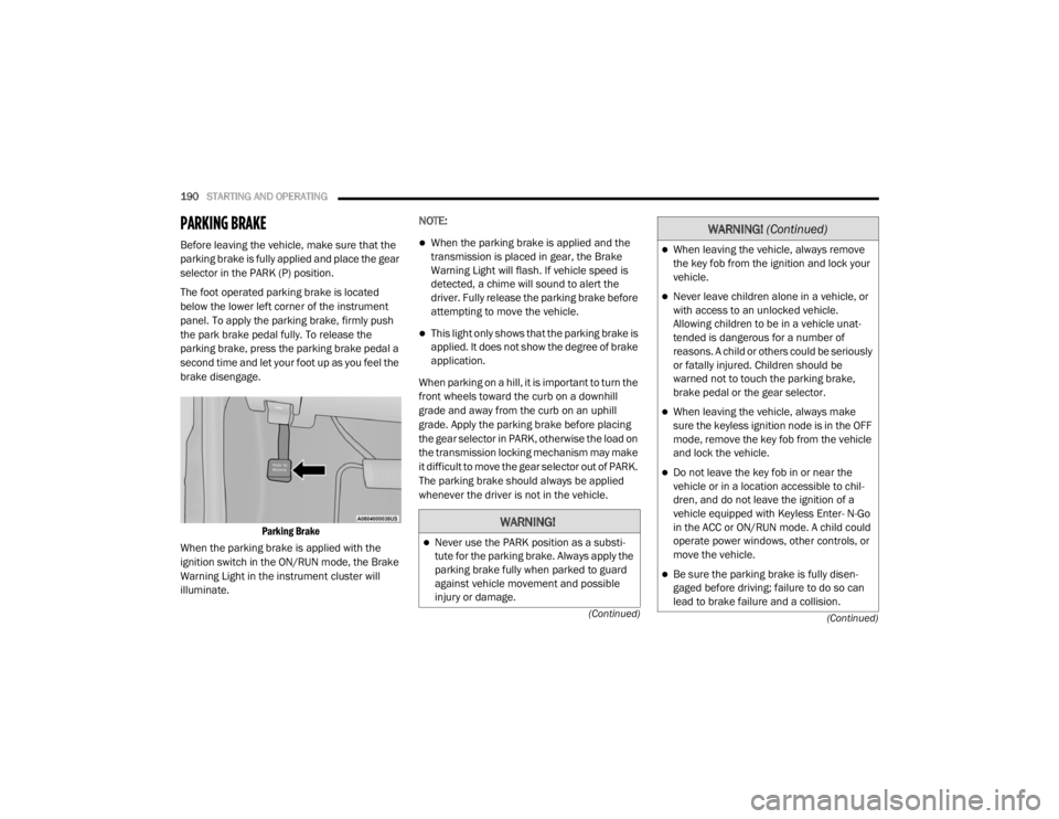
selector in the PARK (P) position.
The foot operated parking brake is located
below the lower left corner of the instrument
panel. To apply the parking brake, firmly push
the park brake pedal fully. To release the
parking brake, press the parking brake pedal a
second time and let your foot up as you feel the
brake disengage.
Parking Brake
When the parking brake is applied with the
ignition switch in the ON/RUN mode, the Brake
Warning Light in the instrument cluster will
illuminate. NOTE:When the parking brake is applied and the
transmission is placed in gear, the Brake
Warning Light will flash. If vehicle speed is
detected, a chime will sound to alert the
driver. Fully release the parking brake before
attempting to move the vehicle.
This light only shows that the parking brake is
applied. It does not show the degree of brake
application.
When parking on a hill, it is important to turn the
front wheels toward the curb on a downhill
grade and away from the curb on an uphill
grade. Apply the parking brake before placing
the gear selector in PARK, otherwise the load on
the transmission locking mechanism may make
it difficult to move the gear selector out of PARK.
The parking brake should always be applied
whenever the driver is not in the vehicle.
WARNING!
Never use the PARK position as a substi -
tute for the parking brake. Always apply the
parking brake fully when parked to guard
against vehicle movement and possible
injury or damage.
When leaving the vehicle, always remove
the key fob from the ignition and lock your
vehicle.
Never leave children alone in a vehicle, or
with access to an unlocked vehicle.
Allowing children to be in a vehicle unat -
tended is dangerous for a number of
reasons. A child or others could be seriously
or fatally injured. Children should be
warned not to touch the parking brake,
brake pedal or the gear selector.
When leaving the vehicle, always make
sure the keyless ignition node is in the OFF
mode, remove the key fob from the vehicle
and lock the vehicle.
Do not leave the key fob in or near the
vehicle or in a location accessible to chil -
dren, and do not leave the ignition of a
vehicle equipped with Keyless Enter- N-Go
in the ACC or ON/RUN mode. A child could
operate power windows, other controls, or
move the vehicle.
Be sure the parking brake is fully disen -
gaged before driving; failure to do so can
lead to brake failure and a collision.
WARNING! (Continued)
20_WD_OM_EN_USC_t.book Page 190
Page 194 of 464
192STARTING AND OPERATING
NOTE:
You must press and hold the brake pedal while
shifting out of PARK.
IGNITION PARK INTERLOCK
This vehicle is equipped with an Ignition Park
Interlock which requires the transmission to be
in PARK (P) before the ignition can be turned to
the OFF mode. This helps the driver avoid
inadvertently leaving the vehicle without placing
the transmission in PARK. This system also
locks the transmission in PARK whenever the
ignition is in the OFF mode.
NOTE:
The transmission is NOT locked in PARK when
the ignition is in the ACC mode (even though the
engine will be off). Ensure that the transmission
is in PARK, and the ignition is OFF (not in ACC
mode) before exiting the vehicle.
BRAKE/TRANSMISSION SHIFT
I
NTERLOCK SYSTEM
This vehicle is equipped with a Brake
Transmission Shift Interlock system (BTSI) that
holds the transmission gear selector in PARK
unless the brakes are applied. To shift the
transmission out of PARK, the engine must be
running and the brake pedal must be pressed.
The brake pedal must also be pressed to shift
from NEUTRAL into DRIVE or REVERSE when the
vehicle is stopped or moving at low speeds.
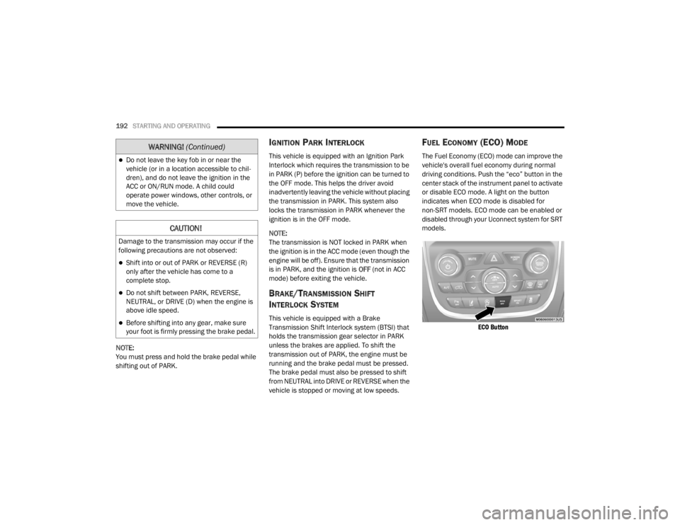
FUEL ECONOMY (ECO) MODE
The Fuel Economy (ECO) mode can improve the
vehicle's overall fuel economy during normal
driving conditions. Push the “eco” button in the
center stack of the instrument panel to activate
or disable ECO mode. A light on the button
indicates when ECO mode is disabled for
non-SRT models. ECO mode can be enabled or
disabled through your Uconnect system for SRT
models.
ECO Button
Do not leave the key fob in or near the
vehicle (or in a location accessible to chil -
dren), and do not leave the ignition in the
ACC or ON/RUN mode. A child could
operate power windows, other controls, or
move the vehicle.
CAUTION!
Damage to the transmission may occur if the
following precautions are not observed:
Shift into or out of PARK or REVERSE (R)
only after the vehicle has come to a
complete stop.
Do not shift between PARK, REVERSE,
NEUTRAL, or DRIVE (D) when the engine is
above idle speed.
Before shifting into any gear, make sure
your foot is firmly pressing the brake pedal.
WARNING! (Continued)
20_WD_OM_EN_USC_t.book Page 192