ECO mode DODGE DURANGO 2020 Owner's Manual
[x] Cancel search | Manufacturer: DODGE, Model Year: 2020, Model line: DURANGO, Model: DODGE DURANGO 2020Pages: 464, PDF Size: 22.14 MB
Page 76 of 464
74GETTING TO KNOW YOUR VEHICLE
CLOSING SUNROOF
Express
Push the switch forward and release it within
one-half second and the sunroof will close
automatically from any position. During Express
Close operation any other actuation of the
sunroof switches will stop the sunroof in a
partially open position.
Manual Mode
Push and hold the switch forward and the
sunroof will close from any position and stop at
a full closed position. Releasing the switch while
the sunroof is in motion will stop the sunroof in
a partially open position.
WIND BUFFETING
Wind buffeting can be described as the
perception of pressure on the ears or a
helicopter-type sound in the ears. Your vehicle
may exhibit wind buffeting with the windows
down, or the sunroof (if equipped) in certain
open or partially open positions. This is a normal
occurrence and can be minimized. If the
buffeting occurs with the rear windows open,
then open the front and rear windows together
to minimize the buffeting. If the buffeting occurs with the sunroof open,
adjust the sunroof opening to minimize the
buffeting or open any window.
SUNSHADE OPERATION
The sunshade can be opened manually.
However, the sunshade will open automatically
as the sunroof opens.
NOTE:
The sunshade cannot be closed if the sunroof is
open.
PINCH PROTECT FEATURE
This feature will detect an obstruction in the
closing of the sunroof during the Express Close
operation. If an obstruction in the path of the
sunroof is detected, the sunroof will
automatically retract. Remove the obstruction if
this occurs.
NOTE:
If three consecutive sunroof close attempts
result in Pinch Protect reversals, Pinch Protect
will disable and the sunroof must be closed in
Manual Mode.
SUNROOF MAINTENANCE
Use only a non-abrasive cleaner and a soft cloth
to clean the glass panel. Periodically check for
and clear out any debris that may have
collected in the tracks.
IGNITION OFF OPERATION
NOTE:
The power sunroof switch can remain active
in Accessory Delay for up to approximately
10 minutes after the vehicle’s ignition is
placed to the OFF position. Opening either
front door will cancel this feature.
This feature is programmable using the Ucon
-
nect System. Refer to “Uconnect Settings” in
“Multimedia” for further information.WARNING!
There is no anti-pinch protection when the
sunroof is almost closed. To avoid personal
injury be sure to clear your arms, hands,
fingers and all objects from the top’s path
before closing.
20_WD_OM_EN_USC_t.book Page 74
Page 82 of 464
80GETTING TO KNOW YOUR VEHICLE
1. Place the ignition in the ON/RUN position.
NOTE:
For vehicles equipped with Keyless Enter-N-Go,
place the ignition in the RUN position with the
engine on. Make sure while programming
HomeLink® with the engine on that your vehicle
is outside of your garage, or that the garage
door remains open at all times.
2. Place the hand-held transmitter 1 to
3 inches (3 to 8 cm) away from the
HomeLink® button you wish to program
while keeping the HomeLink® indicator
light in view.
3. Push and hold the HomeLink® button you want to program while you push and hold
the hand-held transmitter button.
4. Continue to hold both buttons and observe the indicator light. The HomeLink®
indicator will flash slowly and then rapidly
after HomeLink® has received the
frequency signal from the hand-held
transmitter. Release both buttons after the
indicator light changes from slow to rapid. 5. At the garage door opener (in the garage),
locate the “LEARN” or “TRAINING” button.
This can usually be found where the
hanging antenna wire is attached to the
garage door opener/device motor. Firmly
push and release the “LEARN” or
“TRAINING” button. On some garage door
openers/devices there may be a light that
blinks when the garage door opener/device
is in the LEARN/TRAIN mode.
NOTE:
You have 30 seconds in which to initiate the
next step after the LEARN button has been
pushed.
6. Return to the vehicle and push the programmed HomeLink® button twice
(holding the button for two seconds each
time). If the garage door opener/device
activates, programming is complete.
NOTE:
If the garage door opener/device does not acti -
vate, push the button a third time (for two
seconds) to complete the training.
To program the remaining two HomeLink®
buttons, repeat each step for each remain -
ing button. DO NOT erase the channels.Programming A Non-Rolling Code
For programming garage door openers
manufactured before 1995:
1. Place the ignition in the ON/RUN position.
NOTE:
For vehicles equipped with Keyless Enter-N-Go,
place the ignition in the RUN position with the
engine on. Make sure while programming
HomeLink® with the engine on that your vehicle
is outside of your garage, or that the garage
door remains open at all times.
2. Place the hand-held transmitter 1 to 3 inches (3 to 8 cm) away from the
HomeLink® button you wish to program
while keeping the HomeLink® indicator
light in view.
3. Push and hold the Homelink® button you want to program while you push and hold
the hand-held transmitter button.
4. Continue to hold both buttons and observe the indicator light. The Homelink® indicator
will flash slowly and then rapidly after
HomeLink® has received the frequency
signal from the hand-held transmitter.
20_WD_OM_EN_USC_t.book Page 80
Page 84 of 464
82GETTING TO KNOW YOUR VEHICLE
USING HOMELINK®
To operate, place the ignition in the ON/RUN
position and then press and release the
programmed HomeLink® button. Activation will
now occur for the programmed device (i.e.,
garage door opener, gate operator, security
system, entry door lock, home/office lighting,
etc.,). The hand-held transmitter of the device
may also be used at any time. If the ignition is
placed in the OFF position, HomeLink® will
remain active for three minutes. During this
time, if the vehicle is locked, HomeLink® is
disabled.
SECURITY
It is advised to erase all channels before you sell
or turn in your vehicle.
To do this, push and hold the two outside
buttons for 20 seconds until the red indicator
flashes. NOTE:
All channels will be erased. Individual channels
cannot be erased.
The HomeLink® Universal Transceiver is
disabled when the Vehicle Security Alarm is
active.
TROUBLESHOOTING TIPS
If you are having trouble programming
HomeLink®, here are some of the most
common solutions:
Replace the battery in the garage door
opener hand-held transmitter.
Push the LEARN button on the garage door
opener to complete the training for a rolling
code.
Did you unplug the device for programming
and remember to plug it back in?
If you have any problems, or require assistance,
please call toll-free 1-800-355-3515 or, on the
Internet at HomeLink.com for information or
assistance.
WARNING!
Vehicle exhaust contains carbon monoxide,
a dangerous gas. Do not run your vehicle in
the garage while programming the trans -
ceiver. Exhaust gas can cause serious
injury or death.
Your motorized door or gate will open and
close while you are programming the
universal transceiver. Do not program the
transceiver if people, pets or other objects
are in the path of the door or gate. Only use
this transceiver with a garage door opener
that has a “stop and reverse” feature as
required by Federal safety standards. This
includes most garage door opener models
manufactured after 1982. Do not use a
garage door opener without these safety
features.
20_WD_OM_EN_USC_t.book Page 82
Page 96 of 464
94GETTING TO KNOW YOUR VEHICLE
(Continued)
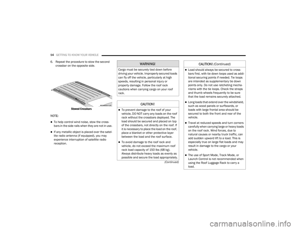
6. Repeat the procedure to stow the second crossbar on the opposite side.
Stowed Crossbars
NOTE:
To help control wind noise, stow the cross -
bars in the side rails when they are not in use.
If any metallic object is placed over the satel -
lite radio antenna (if equipped), you may
experience interruption of satellite radio
reception.
WARNING!
Cargo must be securely tied down before
driving your vehicle. Improperly secured loads
can fly off the vehicle, particularly at high
speeds, resulting in personal injury or
property damage. Follow the roof rack
cautions when carrying cargo on your roof
rack.
CAUTION!
To prevent damage to the roof of your
vehicle, DO NOT carry any loads on the roof
rack without the crossbars deployed. The
load should be secured and placed on top
of the crossbars, not directly on the roof. If
it is necessary to place the load on the roof,
place a blanket or other protective layer
between the load and the roof surface.
To avoid damage to the roof rack and
vehicle, do not exceed the maximum roof
rack load capacity of 150 lbs (68 kg).
Always distribute heavy loads as evenly as
possible and secure the load appropriately.
Load should always be secured to cross -
bars first, with tie down loops used as addi -
tional securing points if needed. Tie loops
are intended as supplementary tie down
points only. Do not use ratcheting mecha -
nisms with the tie loops. Check the straps
and thumb wheels frequently to be sure
that the load remains securely attached.
Long loads that extend over the windshield,
such as wood panels or surfboards, or
loads with large frontal area should be
secured to both the front and rear of the
vehicle.
Travel at reduced speeds and turn corners
carefully when carrying large or heavy loads
on the roof rack. Wind forces, due to
natural causes or nearby truck traffic, can
add sudden upward lift to a load. This is
especially true on large flat loads and may
result in damage to the cargo or your
vehicle.
The use of Sport Mode, Track Mode, or
Launch Control is not recommended when
using the Roof Luggage Rack to carry a
load.
CAUTION! (Continued)
20_WD_OM_EN_USC_t.book Page 94
Page 101 of 464
GETTING TO KNOW YOUR INSTRUMENT PANEL99
INSTRUMENT CLUSTER DISPLAY
Your vehicle will be equipped with an
instrument cluster display, which offers useful
information to the driver. With the ignition in the
OFF mode, opening/closing of a door will
activate the display for viewing, and display the
total miles, or kilometers, in the odometer. Your
instrument cluster display is designed to display
important information about your vehicle’s
systems and features. Using a driver interactive
display located on the instrument panel, your
instrument cluster display can show how
systems are working and give you warnings
when they are not. The steering wheel mounted
controls allow you to scroll through the main
menus and submenus. You can access the
specific information you want and make
selections and adjustments.
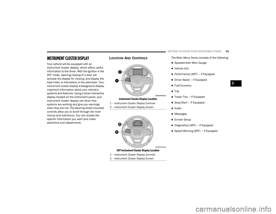
LOCATION AND CONTROLS
Instrument Cluster Display Location
SRT Instrument Cluster Display Location
The Main Menu items consists of the following:
Speedometer Main Gauge
Vehicle Info
Performance (SRT) — If Equipped
Driver Assist — If Equipped
Fuel Economy
Trip
Trailer Tow — If Equipped
Stop/Start — If Equipped
Audio
Messages
Screen Setup
Diagnostics (SRT) — If Equipped
Speed Warning (SRT) — If Equipped
1 – Instrument Cluster Display Controls
2 – Instrument Cluster Display Screen
1 – Instrument Cluster Display Controls
2 – Instrument Cluster Display Screen
3
20_WD_OM_EN_USC_t.book Page 99
Page 106 of 464
104GETTING TO KNOW YOUR INSTRUMENT PANEL
Tire Pressure Monitor System
If tire pressure is OK for all tires a vehicle icon
is displayed with tire pressure values in each
corner of the icon.
If one or more tires have low pressure,
“Inflate Tire To XX” is displayed with the
vehicle icon and the tire pressure values in
each corner of the icon with the pressure
value of the low tire are displayed in a
different color than the other tire pressure
value.
If the Tire Pressure system requires service,
“Service Tire Pressure System” is displayed.
Tire Pressure is an information only function,
and cannot be reset.
Refer to “Tire Pressure Monitoring System
(TPMS)” in “Safety” for further information.
Coolant Temperature — If Equipped
Displays the current temperature of the
coolant.
Transmission Temperature
Displays the actual transmission tempera -
ture. Oil Temperature
Displays the actual oil temperature.
Oil Pressure
Displays the actual oil pressure.
Oil Life
Displays the current oil life of the vehicle.
Battery Voltage
Displays the current voltage level of the
battery.
Storage Mode — If Equipped
Through this option, the vehicle can be
placed into Storage Mode.
SRT Performance Features — If Equipped
Push and release the up or down arrow button
until the SRT icon/title is highlighted in the
instrument cluster display. Push and release
the left or right arrow button to scroll through
the performance feature submenus. The Performance Features include the
following:0-60 mph (0-100 km/h) Timer
Best
Last
Recent
Reaction Time — If Selected
WARNING!
Measurement of vehicle statistics with the
Performance Features is intended for
off-highway or track use only and should not
be done on any public roadways. It is
recommended that these features be used in
a controlled environment and within the limits
of the law. The capabilities of the vehicle as
measured by the performance pages must
never be exploited in a reckless or dangerous
manner, which can jeopardize the user’s
safety or the safety of others. Only a safe,
attentive, and skillful driver can prevent
accidents.
20_WD_OM_EN_USC_t.book Page 104
Page 108 of 464
106GETTING TO KNOW YOUR INSTRUMENT PANEL
Trip
Push and release the up or down arrow button
until the Trip icon/title is highlighted in the
instrument cluster display, then push and
release the left or right arrow button to select
Trip A or Trip B.
The Trip A and Trip B information will display the
following:
Distance
Average Fuel Economy
Elapsed Time
Hold the OK button to reset all the information.
Trailer Tow — If Equipped
Push and release the up or down arrow button
until the Trailer Tow Menu icon/title is
highlighted in the instrument cluster display.
Push and release the left or right arrow button
to select Trailer Trip or Trailer Brake.
Trailer Trip will display the following:
Distance
NOTE:
Press and hold the OK button to reset all the
information. Trailer Brake will display the following:
Output
Type
Gain
Stop/Start – If Equipped
Push and release the
up or down
arrow button on the steering wheel to
scroll to the Stop/Start menu in the
driver interactive display.
For further information on the use and different
modes of the Stop/Start System, refer to “Stop/
Start System – If Equipped” in “Starting And
Operating”.
Audio
Push and release the up or down arrow button
until the Audio Menu icon/title is highlighted in
the instrument cluster display. This menu will
display the audio source information, including
the Song name, Artist name, and audio source
with an accompanying graphic.
Stored Messages
Push and release the up or down arrow button
until the Messages Menu item is highlighted. This feature shows the number of stored
warning messages. Pushing the
left or right
arrow button will allow you to see what the
stored messages are.
When no messages are present, main menu
icon will be a closed envelope.
Screen Setup
Push and release the up or down arrow button
until the Screen Setup Menu icon/title is
highlighted in the instrument cluster display.
Push and release the OK button to enter the
submenus and follow the prompts on the
screen as needed. The Screen Setup feature
allows you to change what information is
displayed in the instrument cluster as well as
the location that information is displayed.
Current Gear
On
Off (default setting)
Gear Display
Full (default setting)
Single
20_WD_OM_EN_USC_t.book Page 106
Page 116 of 464
114GETTING TO KNOW YOUR INSTRUMENT PANEL
Electronic Stability Control (ESC) Active
Warning Light
This warning light will indicate when
the Electronic Stability Control (ESC)
system is Active. The “ESC Indicator
Light” in the instrument cluster will
come on when the ignition is placed in the
ON/RUN or ACC/ON/RUN position, and when
ESC is activated. It should go out with the
engine running. If the “ESC Indicator Light”
comes on continuously with the engine running,
a malfunction has been detected in the ESC
system. If this warning light remains on after
several ignition cycles, and the vehicle has been
driven several miles (kilometers) at speeds
greater than 30 mph (48 km/h), see an
authorized dealer as soon as possible to have
the problem diagnosed and corrected.
The “ESC OFF Indicator Light” and the “ESC
Indicator Light” come on momentarily each
time the ignition is placed in the ON/RUN or
ACC/ON/RUN position.
The ESC system will make buzzing or clicking
sounds when it is active. This is normal; the
sounds will stop when ESC becomes inactive.
This light will come on when the vehicle is in
an ESC event.
Electronic Stability Control (ESC) OFF
Warning Light
This warning light indicates the
Electronic Stability Control (ESC) is
off.
Each time the ignition is turned to ON/RUN or
ACC/ON/RUN, the ESC system will be on, even
if it was turned off previously.
The ESC OFF indicator will be lit any time the
Traction Mode is set to Sport, Track or Full OFF
in Drive Modes.
Low Washer Fluid Warning Light — If
Equipped
This warning light will illuminate when
the windshield washer fluid is low.
Refer to “Adding Washer Fluid” in
“Servicing And Maintenance” for
further information.
Tire Pressure Monitoring System (TPMS)
Warning Light
The warning light switches on and a
message is displayed to indicate that
the tire pressure is lower than the
recommended value and/or that slow
pressure loss is occurring. In these cases,
optimal tire duration and fuel consumption may
not be guaranteed.
Should one or more tires be in the condition
mentioned above, the display will show the
indications corresponding to each tire.
CAUTION!
Prolonged driving with the Malfunction
Indicator Light (MIL) on could cause damage
to the vehicle control system. It also could
affect fuel economy and driveability. If the
MIL is flashing, severe catalytic converter
damage and power loss will soon occur.
Immediate service is required.
20_WD_OM_EN_USC_t.book Page 114
Page 119 of 464
GETTING TO KNOW YOUR INSTRUMENT PANEL117
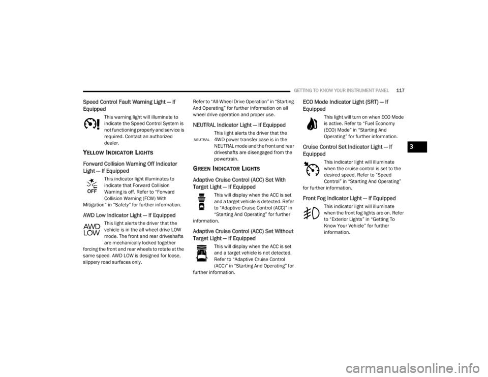
Speed Control Fault Warning Light — If
Equipped
This warning light will illuminate to
indicate the Speed Control System is
not functioning properly and service is
required. Contact an authorized
dealer.
YELLOW INDICATOR LIGHTS
Forward Collision Warning Off Indicator
Light — If Equipped
This indicator light illuminates to
indicate that Forward Collision
Warning is off. Refer to “Forward
Collision Warning (FCW) With
Mitigation” in “Safety” for further information.
AWD Low Indicator Light — If Equipped
This light alerts the driver that the
vehicle is in the all wheel drive LOW
mode. The front and rear driveshafts
are mechanically locked together
forcing the front and rear wheels to rotate at the
same speed. AWD LOW is designed for loose,
slippery road surfaces only. Refer to “All-Wheel Drive Operation” in “Starting
And Operating” for further information on all
wheel drive operation and proper use.
NEUTRAL Indicator Light — If Equipped
This light alerts the driver that the
4WD power transfer case is in the
NEUTRAL mode and the front and rear
driveshafts are disengaged from the
powertrain.
GREEN INDICATOR LIGHTS
Adaptive Cruise Control (ACC) Set With
Target Light — If Equipped
This will display when the ACC is set
and a target vehicle is detected. Refer
to “Adaptive Cruise Control (ACC)” in
“Starting And Operating” for further
information.
Adaptive Cruise Control (ACC) Set Without
Target Light — If Equipped
This will display when the ACC is set
and a target vehicle is not detected.
Refer to “Adaptive Cruise Control
(ACC)” in “Starting And Operating” for
further information.
ECO Mode Indicator Light (SRT) — If
Equipped
This light will turn on when ECO Mode
is active. Refer to “Fuel Economy
(ECO) Mode” in “Starting And
Operating” for further information.
Cruise Control Set Indicator Light — If
Equipped
This indicator light will illuminate
when the cruise control is set to the
desired speed. Refer to “Speed
Control” in “Starting And Operating”
for further information.
Front Fog Indicator Light — If Equipped
This indicator light will illuminate
when the front fog lights are on. Refer
to “Exterior Lights” in “Getting To
Know Your Vehicle” for further
information.
3
20_WD_OM_EN_USC_t.book Page 117
Page 125 of 464
SAFETY123
ABS is designed to function with the Original
Equipment Manufacturer (OEM) tires.
Modification may result in degraded ABS
performance.
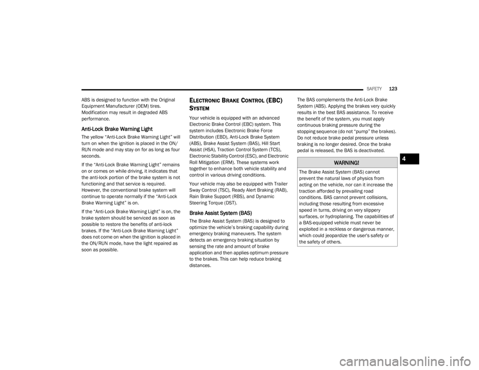
Anti-Lock Brake Warning Light
The yellow “Anti-Lock Brake Warning Light” will
turn on when the ignition is placed in the ON/
RUN mode and may stay on for as long as four
seconds.
If the “Anti-Lock Brake Warning Light” remains
on or comes on while driving, it indicates that
the anti-lock portion of the brake system is not
functioning and that service is required.
However, the conventional brake system will
continue to operate normally if the “Anti-Lock
Brake Warning Light” is on.
If the “Anti-Lock Brake Warning Light” is on, the
brake system should be serviced as soon as
possible to restore the benefits of anti-lock
brakes. If the “Anti-Lock Brake Warning Light”
does not come on when the ignition is placed in
the ON/RUN mode, have the light repaired as
soon as possible.
ELECTRONIC BRAKE CONTROL (EBC)
S
YSTEM
Your vehicle is equipped with an advanced
Electronic Brake Control (EBC) system. This
system includes Electronic Brake Force
Distribution (EBD), Anti-Lock Brake System
(ABS), Brake Assist System (BAS), Hill Start
Assist (HSA), Traction Control System (TCS),
Electronic Stability Control (ESC), and Electronic
Roll Mitigation (ERM). These systems work
together to enhance both vehicle stability and
control in various driving conditions.
Your vehicle may also be equipped with Trailer
Sway Control (TSC), Ready Alert Braking (RAB),
Rain Brake Support (RBS), and Dynamic
Steering Torque (DST).
Brake Assist System (BAS)
The Brake Assist System (BAS) is designed to
optimize the vehicle’s braking capability during
emergency braking maneuvers. The system
detects an emergency braking situation by
sensing the rate and amount of brake
application and then applies optimum pressure
to the brakes. This can help reduce braking
distances. The BAS complements the Anti-Lock Brake
System (ABS). Applying the brakes very quickly
results in the best BAS assistance. To receive
the benefit of the system, you must apply
continuous braking pressure during the
stopping sequence (do not “pump” the brakes).
Do not reduce brake pedal pressure unless
braking is no longer desired. Once the brake
pedal is released, the BAS is deactivated.
WARNING!
The Brake Assist System (BAS) cannot
prevent the natural laws of physics from
acting on the vehicle, nor can it increase the
traction afforded by prevailing road
conditions. BAS cannot prevent collisions,
including those resulting from excessive
speed in turns, driving on very slippery
surfaces, or hydroplaning. The capabilities of
a BAS-equipped vehicle must never be
exploited in a reckless or dangerous manner,
which could jeopardize the user's safety or
the safety of others.
4
20_WD_OM_EN_USC_t.book Page 123