roof DODGE DURANGO 2020 Owners Manual
[x] Cancel search | Manufacturer: DODGE, Model Year: 2020, Model line: DURANGO, Model: DODGE DURANGO 2020Pages: 464, PDF Size: 22.14 MB
Page 5 of 464
3
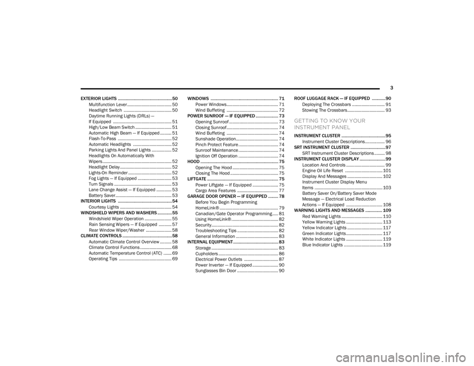
EXTERIOR LIGHTS ................................................50 Multifunction Lever ...................................... 50
Headlight Switch ......................................... 50
Daytime Running Lights (DRLs) —
If Equipped .................................................. 51 High/Low Beam Switch ............................... 51
Automatic High Beam — If Equipped .......... 51
Flash-To-Pass .............................................. 52
Automatic Headlights ................................. 52
Parking Lights And Panel Lights ................. 52
Headlights On Automatically With
Wipers........................................................... 52 Headlight Delay ............................................ 52
Lights-On Reminder ..................................... 52
Fog Lights — If Equipped ............................. 53
Turn Signals ................................................. 53
Lane Change Assist — If Equipped ............. 53
Battery Saver................................................ 53
INTERIOR LIGHTS ................................................54
Courtesy Lights ............................................ 54
WINDSHIELD WIPERS AND WASHERS .............55
Windshield Wiper Operation ....................... 55
Rain Sensing Wipers — If Equipped ........... 57
Rear Window Wiper/Washer ...................... 58
CLIMATE CONTROLS ............................................58
Automatic Climate Control Overview .......... 58
Climate Control Functions ........................... 68
Automatic Temperature Control (ATC) ....... 69
Operating Tips ............................................. 69 WINDOWS ............................................................ 71
Power Windows............................................ 71
Wind Buffeting ............................................ 72
POWER SUNROOF — IF EQUIPPED .................... 73
Opening Sunroof .......................................... 73
Closing Sunroof............................................ 74
Wind Buffeting ............................................ 74
Sunshade Operation.................................... 74
Pinch Protect Feature.................................. 74
Sunroof Maintenance.................................. 74
Ignition Off Operation .................................. 74
HOOD ..................................................................... 75
Opening The Hood ....................................... 75
Closing The Hood ......................................... 75
LIFTGATE ............................................................... 75
Power Liftgate — If Equipped ...................... 75
Cargo Area Features ................................... 77
GARAGE DOOR OPENER — IF EQUIPPED ......... 78
Before You Begin Programming
HomeLink® .................................................. 79 Canadian/Gate Operator Programming ..... 81
Using HomeLink®........................................ 82
Security......................................................... 82
Troubleshooting Tips ................................... 82
General Information .................................... 83
INTERNAL EQUIPMENT ........................................ 83
Storage ......................................................... 83
Cupholders ................................................... 86
Electrical Power Outlets ............................. 87
Power Inverter — If Equipped ...................... 90
Sunglasses Bin Door ................................... 90 ROOF LUGGAGE RACK — IF EQUIPPED ............90
Deploying The Crossbars ............................ 91
Stowing The Crossbars................................ 93
GETTING TO KNOW YOUR
INSTRUMENT PANEL
INSTRUMENT CLUSTER .......................................95Instrument Cluster Descriptions................. 96
SRT INSTRUMENT CLUSTER ...............................97
SRT Instrument Cluster Descriptions ......... 98
INSTRUMENT CLUSTER DISPLAY .......................99
Location And Controls ................................. 99
Engine Oil Life Reset ................................ 101
Display And Messages .............................. 102
Instrument Cluster Display Menu
Items .......................................................... 103 Battery Saver On/Battery Saver Mode
Message — Electrical Load Reduction
Actions — If Equipped ............................... 108
WARNING LIGHTS AND MESSAGES ............... 109
Red Warning Lights ................................... 110
Yellow Warning Lights ............................... 113Yellow Indicator Lights .............................. 117
Green Indicator Lights ............................... 117White Indicator Lights ............................... 119Blue Indicator Lights ................................. 119
20_WD_OM_EN_USC_t.book Page 3
Page 20 of 464
18GETTING TO KNOW YOUR VEHICLE
(Continued)
NOTE:
In case the ignition switch does not change with
the push of a button, the key fob may have a low
or depleted battery. In this situation, a back up
method can be used to operate the ignition
switch. Put the nose side of the key fob (side
opposite of the emergency key) against the
START/STOP ignition button and push to
operate the ignition switch.
IGNITION OR ACCESSORY ON MESSAGE
Upon opening the driver's door when the
ignition is in ACC or ON (engine not running), a
chime will sound to remind you to place the
ignition in the OFF position. In addition to the
chime, the ignition or accessory on message will
display in the cluster.
NOTE:
With the Uconnect system, the power window
switches, radio, power sunroof (if equipped),
and power outlets will remain active for up to
10 minutes after the ignition is placed in the
OFF position. Opening either front door will
cancel this feature. The timing for this feature is programmable.
Refer to “Uconnect Settings” in “Multimedia”
for further information.
DEPLETED KEY FOB BATTERY
Key Not Detected Feature
If the ignition position does not change with a
push of the ignition button, and the instrument
cluster display message “Key Fob Not
Detected” is being displayed, the key fob may
have a low or depleted battery. In this situation,
a back up method can be used to operate the
keyless push button ignition.
WARNING!
Before exiting a vehicle, always shift the
automatic transmission into PARK and
apply the parking brake. Always make sure
the keyless ignition node is in the “OFF”
mode, remove the key fob from the vehicle
and lock the vehicle.
Never leave children alone in a vehicle, or
with access to an unlocked vehicle.
Allowing children to be in a vehicle unat
-
tended is dangerous for a number of
reasons. A child or others could be seriously
or fatally injured. Children should be
warned not to touch the parking brake,
brake pedal or the gear selector.
Do not leave the key fob in or near the
vehicle, or in a location accessible to chil-
dren, and do not leave the ignition of a
vehicle equipped with Keyless Enter-N-Go
in the ACC or ON/RUN mode. A child could
operate power windows, other controls, or
move the vehicle.
Do not leave children or animals inside
parked vehicles in hot weather. Interior
heat build-up may cause serious injury or
death.
CAUTION!
An unlocked vehicle is an invitation. Always
remove the key fobs from vehicle, place the
ignition in the OFF position and lock all doors
when leaving the vehicle unattended.
WARNING! (Continued)
20_WD_OM_EN_USC_t.book Page 18
Page 22 of 464
20GETTING TO KNOW YOUR VEHICLE
REMOTE START ABORT MESSAGE — IF
E
QUIPPED
The following messages will display in the
instrument cluster display if the vehicle fails to
remote start or exits remote start prematurely:
Remote Start Aborted — Door Open
Remote Start Aborted — Hood Open
Remote Start Aborted — Liftgate Open
Remote Start Aborted — Fuel Low
Remote Start Disabled — Start Vehicle To
Reset
The Remote Start Abort message stays active
until the ignition is placed in the ON/RUN
position.
TO ENTER REMOTE START MODE
Push and release the remote start button on the
key fob twice within five seconds. The vehicle
doors will lock, the parking lights will flash, and
the horn will chirp twice (if programmed). Then,
the engine will start, and the vehicle will remain
in the Remote Start mode for a 15 minute cycle. NOTE:
If an engine fault is present or fuel level is
low, the vehicle will start and then shut down
in 10 seconds.
The park lamps will turn on and remain on
during Remote Start mode.
For security, power window and power
sunroof operation (if equipped) are disabled
when the vehicle is in the Remote Start
mode.
The engine can be started two consecutive
times with the key fob. However, the ignition
must be cycled by pushing the START/STOP
ignition button twice (or the ignition switch
must be placed in the ON/RUN position)
before you can repeat the start sequence for
a third cycle.
TO EXIT REMOTE START MODE
W
ITHOUT DRIVING THE VEHICLE
Push and release the remote start button one
time or allow the engine to run for the entire
15 minute cycle. NOTE:
To avoid unintentional shutdowns, the system
will disable for two seconds after receiving a
valid Remote Start request.
TO EXIT REMOTE START MODE AND
D
RIVE THE VEHICLE
Before the end of 15 minute cycle, push and
release the unlock button on the key fob to
unlock the doors, or unlock the vehicle using
Keyless Enter-N-Go — Passive Entry via the door
handles, and disarm the vehicle security alarm
(if equipped). Then, prior to the end of the
15 minute cycle, push and release the START/
STOP ignition button.
NOTE:
For vehicles equipped with the Keyless
Enter-N-Go — Passive Entry feature, the
message “Remote Start Active — Push Start
Button” will display in the instrument cluster
display until you push the ignition START/STOP
ignition button.
20_WD_OM_EN_USC_t.book Page 20
Page 74 of 464
72GETTING TO KNOW YOUR VEHICLE
Auto-Up Feature With Anti-Pinch Protection
— Driver And Front Passenger Door Only
Lift the window switch fully upward to the
second detent, release, and the window will go
up automatically.
To stop the window from going all the way up
during the Auto-Up operation, push down on the
switch briefly.
To close the window part way, lift the window
switch to the first detent and release when you
want the window to stop.
NOTE:
If the window runs into any obstacle during
Auto-Up, it will reverse direction and then go
back down. Remove the obstacle and use the
window switch again to close the window. Any
impact due to rough road conditions may trigger
the auto reverse function unexpectedly during
Auto-Up. If this happens, pull the switch lightly
to the first detent and hold it to close the
window manually.
Reset Auto-Up
Should the Auto-Up feature stop working, the
window may need to be reset. To reset Auto-Up:
1. Make sure the door is fully closed.
2. Pull the window switch up to close the
window completely and continue to hold the
switch up for an additional two seconds
after the window is closed.
3. Push the window switch down firmly to the second detent to open the window
completely and continue to hold the switch
down for an additional two seconds after
the window is fully open.
Window Lockout Switch
The window lockout switch on the driver's door
trim panel allows you to disable the window
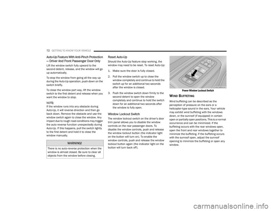
controls on the rear passenger doors. To
disable the window controls, push and release
the window lockout button (the indicator light
on the button will turn on). To enable the
window controls, push and release the window
lockout button again (the indicator light on the
button will turn back off).
Power Window Lockout Switch
WIND BUFFETING
Wind buffeting can be described as the
perception of pressure on the ears or a
helicopter-type sound in the ears. Your vehicle
may exhibit wind buffeting with the windows
down, or the sunroof (if equipped) in certain
open or partially open positions. This is a normal
occurrence and can be minimized. If the
buffeting occurs with the rear windows open,
open the front and rear windows together to
minimize the buffeting. If the buffeting occurs
with the sunroof open, adjust the sunroof
opening to minimize the buffeting or open any
window.
WARNING!
There is no auto-reverse protection when the
window is almost closed. Be sure to clear all
objects from the window before closing.
20_WD_OM_EN_USC_t.book Page 72
Page 75 of 464
GETTING TO KNOW YOUR VEHICLE73
POWER SUNROOF — IF EQUIPPED
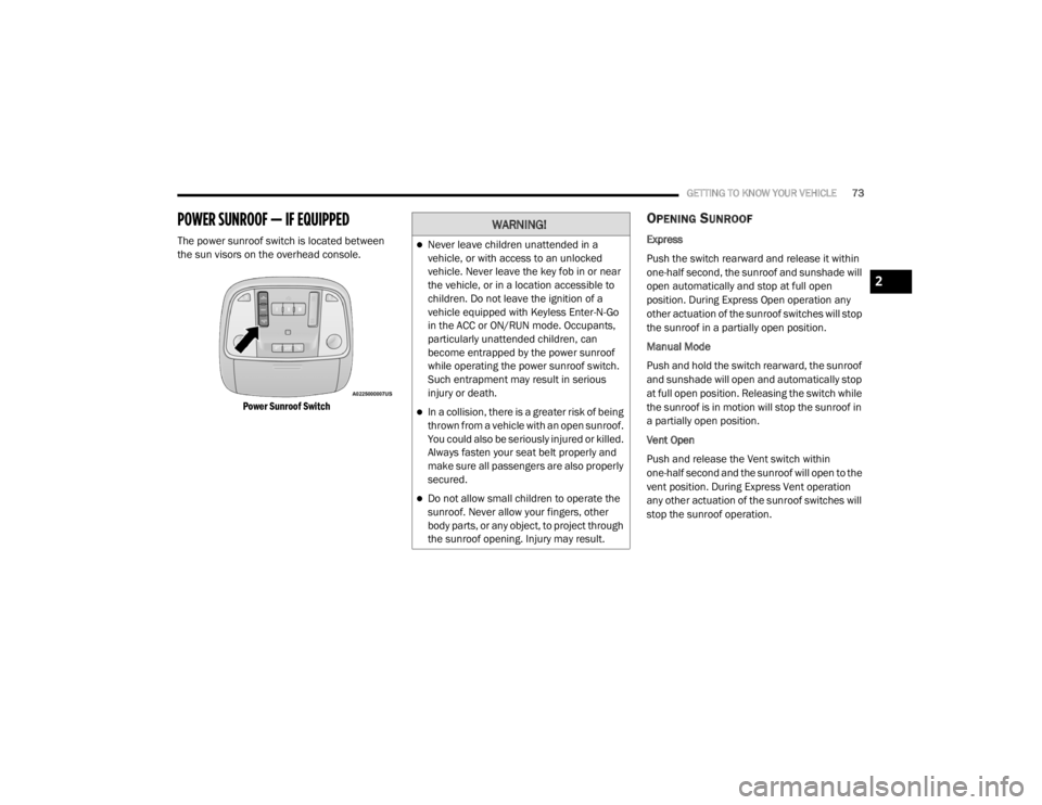
The power sunroof switch is located between
the sun visors on the overhead console.
Power Sunroof Switch
OPENING SUNROOF
Express
Push the switch rearward and release it within
one-half second, the sunroof and sunshade will
open automatically and stop at full open
position. During Express Open operation any
other actuation of the sunroof switches will stop
the sunroof in a partially open position.
Manual Mode
Push and hold the switch rearward, the sunroof
and sunshade will open and automatically stop
at full open position. Releasing the switch while
the sunroof is in motion will stop the sunroof in
a partially open position.
Vent Open
Push and release the Vent switch within
one-half second and the sunroof will open to the
vent position. During Express Vent operation
any other actuation of the sunroof switches will
stop the sunroof operation.
WARNING!
Never leave children unattended in a
vehicle, or with access to an unlocked
vehicle. Never leave the key fob in or near
the vehicle, or in a location accessible to
children. Do not leave the ignition of a
vehicle equipped with Keyless Enter-N-Go
in the ACC or ON/RUN mode. Occupants,
particularly unattended children, can
become entrapped by the power sunroof
while operating the power sunroof switch.
Such entrapment may result in serious
injury or death.
In a collision, there is a greater risk of being
thrown from a vehicle with an open sunroof.
You could also be seriously injured or killed.
Always fasten your seat belt properly and
make sure all passengers are also properly
secured.
Do not allow small children to operate the
sunroof. Never allow your fingers, other
body parts, or any object, to project through
the sunroof opening. Injury may result.
2
20_WD_OM_EN_USC_t.book Page 73
Page 76 of 464
74GETTING TO KNOW YOUR VEHICLE
CLOSING SUNROOF
Express
Push the switch forward and release it within
one-half second and the sunroof will close
automatically from any position. During Express
Close operation any other actuation of the
sunroof switches will stop the sunroof in a
partially open position.
Manual Mode
Push and hold the switch forward and the
sunroof will close from any position and stop at
a full closed position. Releasing the switch while
the sunroof is in motion will stop the sunroof in
a partially open position.
WIND BUFFETING
Wind buffeting can be described as the
perception of pressure on the ears or a
helicopter-type sound in the ears. Your vehicle
may exhibit wind buffeting with the windows
down, or the sunroof (if equipped) in certain
open or partially open positions. This is a normal
occurrence and can be minimized. If the
buffeting occurs with the rear windows open,
then open the front and rear windows together
to minimize the buffeting. If the buffeting occurs with the sunroof open,
adjust the sunroof opening to minimize the
buffeting or open any window.
SUNSHADE OPERATION
The sunshade can be opened manually.
However, the sunshade will open automatically
as the sunroof opens.
NOTE:
The sunshade cannot be closed if the sunroof is
open.
PINCH PROTECT FEATURE
This feature will detect an obstruction in the
closing of the sunroof during the Express Close
operation. If an obstruction in the path of the
sunroof is detected, the sunroof will
automatically retract. Remove the obstruction if
this occurs.
NOTE:
If three consecutive sunroof close attempts
result in Pinch Protect reversals, Pinch Protect
will disable and the sunroof must be closed in
Manual Mode.
SUNROOF MAINTENANCE
Use only a non-abrasive cleaner and a soft cloth
to clean the glass panel. Periodically check for
and clear out any debris that may have
collected in the tracks.
IGNITION OFF OPERATION
NOTE:
The power sunroof switch can remain active
in Accessory Delay for up to approximately
10 minutes after the vehicle’s ignition is
placed to the OFF position. Opening either
front door will cancel this feature.
This feature is programmable using the Ucon
-
nect System. Refer to “Uconnect Settings” in
“Multimedia” for further information.WARNING!
There is no anti-pinch protection when the
sunroof is almost closed. To avoid personal
injury be sure to clear your arms, hands,
fingers and all objects from the top’s path
before closing.
20_WD_OM_EN_USC_t.book Page 74
Page 92 of 464
90GETTING TO KNOW YOUR VEHICLE
POWER INVERTER — IF EQUIPPED
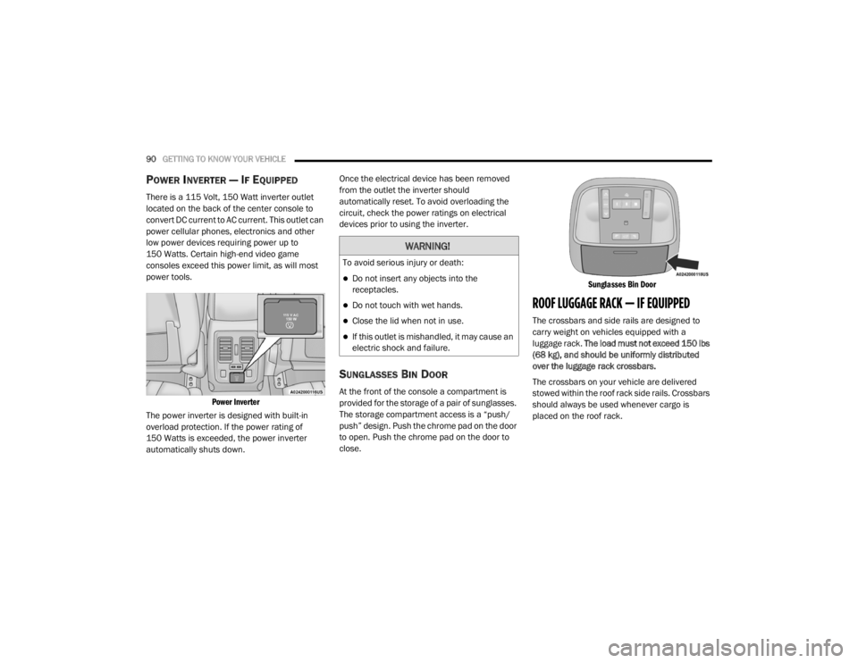
There is a 115 Volt, 150 Watt inverter outlet
located on the back of the center console to
convert DC current to AC current. This outlet can
power cellular phones, electronics and other
low power devices requiring power up to
150 Watts. Certain high-end video game
consoles exceed this power limit, as will most
power tools.
Power Inverter
The power inverter is designed with built-in
overload protection. If the power rating of
150 Watts is exceeded, the power inverter
automatically shuts down. Once the electrical device has been removed
from the outlet the inverter should
automatically reset. To avoid overloading the
circuit, check the power ratings on electrical
devices prior to using the inverter.
SUNGLASSES BIN DOOR
At the front of the console a compartment is
provided for the storage of a pair of sunglasses.
The storage compartment access is a “push/
push” design. Push the chrome pad on the door
to open. Push the chrome pad on the door to
close.
Sunglasses Bin Door
ROOF LUGGAGE RACK — IF EQUIPPED
The crossbars and side rails are designed to
carry weight on vehicles equipped with a
luggage rack.
The load must not exceed 150 lbs
(68 kg), and should be uniformly distributed
over the luggage rack crossbars.
The crossbars on your vehicle are delivered
stowed within the roof rack side rails. Crossbars
should always be used whenever cargo is
placed on the roof rack.
WARNING!
To avoid serious injury or death:
Do not insert any objects into the
receptacles.
Do not touch with wet hands.
Close the lid when not in use.
If this outlet is mishandled, it may cause an
electric shock and failure.
20_WD_OM_EN_USC_t.book Page 90
Page 93 of 464
GETTING TO KNOW YOUR VEHICLE91
Check the straps frequently to be sure that the
load remains securely attached.
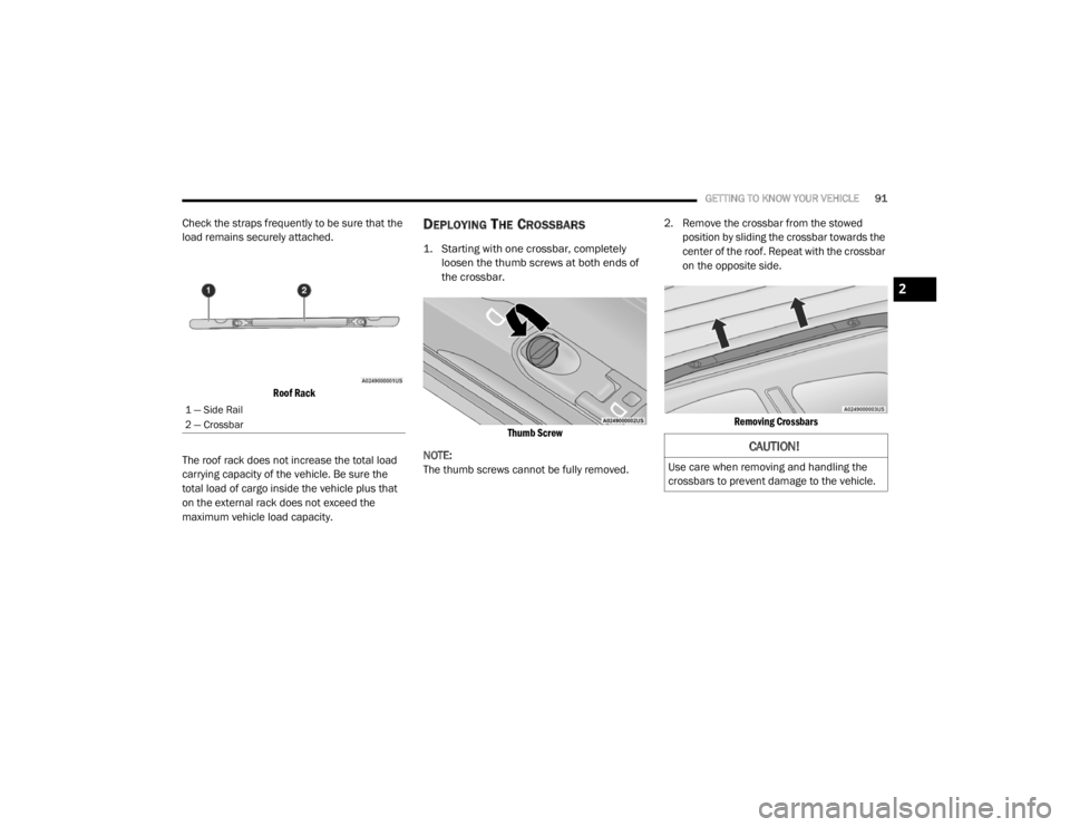
Roof Rack
The roof rack does not increase the total load
carrying capacity of the vehicle. Be sure the
total load of cargo inside the vehicle plus that
on the external rack does not exceed the
maximum vehicle load capacity.DEPLOYING THE CROSSBARS
1. Starting with one crossbar, completely loosen the thumb screws at both ends of
the crossbar.
Thumb Screw
NOTE:
The thumb screws cannot be fully removed. 2. Remove the crossbar from the stowed
position by sliding the crossbar towards the
center of the roof. Repeat with the crossbar
on the opposite side.
Removing Crossbars
1 — Side Rail
2 — Crossbar
CAUTION!
Use care when removing and handling the
crossbars to prevent damage to the vehicle.
2
20_WD_OM_EN_USC_t.book Page 91
Page 94 of 464
92GETTING TO KNOW YOUR VEHICLE
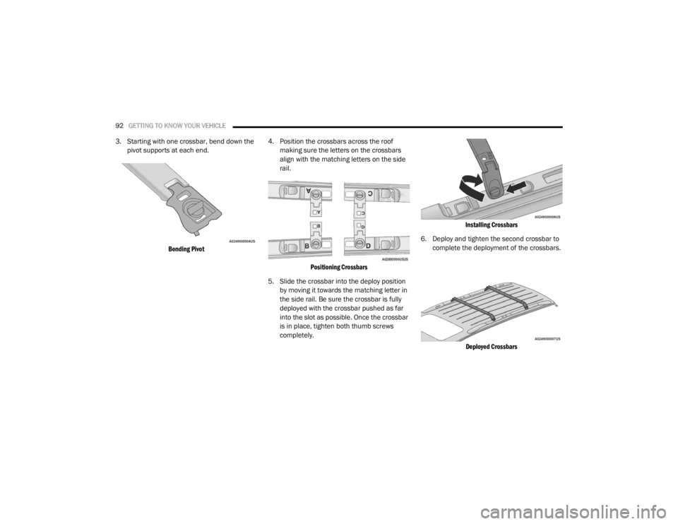
3. Starting with one crossbar, bend down the
pivot supports at each end.
Bending Pivot
4. Position the crossbars across the roof
making sure the letters on the crossbars
align with the matching letters on the side
rail.
Positioning Crossbars
5. Slide the crossbar into the deploy position by moving it towards the matching letter in
the side rail. Be sure the crossbar is fully
deployed with the crossbar pushed as far
into the slot as possible. Once the crossbar
is in place, tighten both thumb screws
completely.
Installing Crossbars
6. Deploy and tighten the second crossbar to complete the deployment of the crossbars.
Deployed Crossbars
20_WD_OM_EN_USC_t.book Page 92
Page 95 of 464
GETTING TO KNOW YOUR VEHICLE93
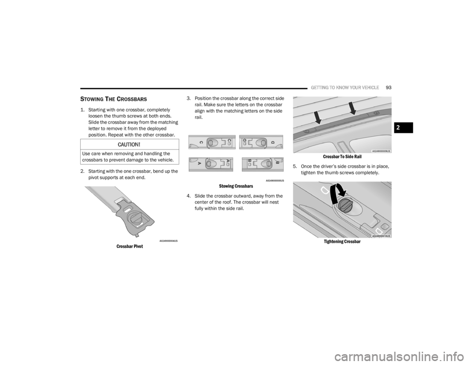
STOWING THE CROSSBARS
1. Starting with one crossbar, completely
loosen the thumb screws at both ends.
Slide the crossbar away from the matching
letter to remove it from the deployed
position. Repeat with the other crossbar.
2. Starting with the one crossbar, bend up the pivot supports at each end.
Crossbar Pivot
3. Position the crossbar along the correct side
rail. Make sure the letters on the crossbar
align with the matching letters on the side
rail.
Stowing Crossbars
4. Slide the crossbar outward, away from the center of the roof. The crossbar will nest
fully within the side rail.
Crossbar To Side Rail
5. Once the driver’s side crossbar is in place, tighten the thumb screws completely.
Tightening Crossbar
CAUTION!
Use care when removing and handling the
crossbars to prevent damage to the vehicle.
2
20_WD_OM_EN_USC_t.book Page 93