Fuel DODGE DURANGO 2022 Owner's Manual
[x] Cancel search | Manufacturer: DODGE, Model Year: 2022, Model line: DURANGO, Model: DODGE DURANGO 2022Pages: 332, PDF Size: 19.82 MB
Page 139 of 332
STARTING AND OPERATING137
vehicle is shifted into PARK, the vehicle’s ignition is
placed in the OFF position, or the touchscreen X
button to disable the display of the Rear View
Camera is pressed.
When enabled, active guidelines are overlaid on
the image to illustrate the width of the vehicle and
its projected backup path based on the steering
wheel position. A dashed center line overlay
indicates the center of the vehicle to assist with
parking or aligning to a hitch/receiver. Different
colored zones indicate the distance to the rear of
the vehicle.
The following table shows the approximate
distances for each zone:
NOTE:If snow, ice, mud, or any foreign substance builds
up on the camera lens, clean the lens, rinse with
water, and dry with a soft cloth. Do not cover the
lens.
Rear View Camera — Viewing At Speed When the vehicle is in PARK, NEUTRAL or
DRIVE, the Rear View Camera can be
activated with the Rear View Camera
button in the Controls tab of the Vehicle
Menu. This feature allows the customer to monitor
the area directly behind the vehicle (or trailer, if
equipped) for up to 10 seconds while driving. If the
vehicle speed remains below 8 mph (13 km/h),
the Rear View Camera image will be displayed
continuously until deactivated via the X button on
the touchscreen.
REFUELING THE VEHICLE
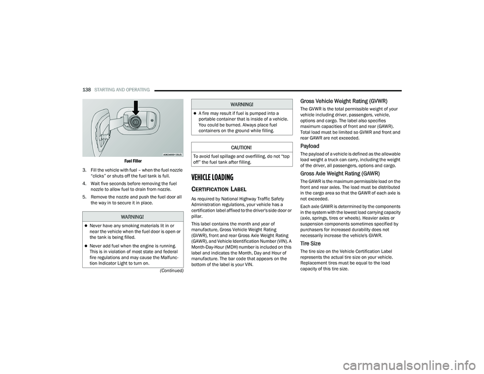
1. Open the fuel filler door by pushing on the outer edge of the fuel door.
NOTE:There is no fuel filler cap. Two flapper doors inside
the pipe seal the system.
2. Insert the fuel nozzle fully into the filler pipe – the nozzle opens and holds the flapper doors
while refueling.
Zone
Distance To The Rear Of
The Vehicle
Red 0 - 1 ft (0 - 30 cm)
Yellow 1 ft - 6.5 ft (30 cm - 2 m)
Green 6.5 ft or greater
(2 m or greater)
WARNING!
Drivers must be careful when backing up even
when using the ParkView Rear Back Up Camera.
Always check carefully behind your vehicle, and
be sure to check for pedestrians, animals, other
vehicles, obstructions, or blind spots before
backing up. You are responsible for the safety of
your surroundings and must continue to pay
attention while backing up. Failure to do so can
result in serious injury or death.
CAUTION!
To avoid vehicle damage, ParkView should
only be used as a parking aid. The ParkView
camera is unable to view every obstacle or
object in your drive path.
To avoid vehicle damage, the vehicle must be
driven slowly when using ParkView to be able
to stop in time when an obstacle is seen. It is
recommended that the driver look frequently
over his/her shoulder when using ParkView.
4
22_WD_OM_EN_USC_t.book Page 137
Page 140 of 332
138STARTING AND OPERATING
(Continued)
Fuel Filler
3. Fill the vehicle with fuel – when the fuel nozzle “clicks” or shuts off the fuel tank is full.
4. Wait five seconds before removing the fuel nozzle to allow fuel to drain from nozzle.
5. Remove the nozzle and push the fuel door all the way in to secure it in place.
VEHICLE LOADING
CERTIFICATION LABEL
As required by National Highway Traffic Safety
Administration regulations, your vehicle has a
certification label affixed to the driver's side door or
pillar.
This label contains the month and year of
manufacture, Gross Vehicle Weight Rating
(GVWR), front and rear Gross Axle Weight Rating
(GAWR), and Vehicle Identification Number (VIN). A
Month-Day-Hour (MDH) number is included on this
label and indicates the Month, Day and Hour of
manufacture. The bar code that appears on the
bottom of the label is your VIN.
Gross Vehicle Weight Rating (GVWR)
The GVWR is the total permissible weight of your
vehicle including driver, passengers, vehicle,
options and cargo. The label also specifies
maximum capacities of front and rear (GAWR).
Total load must be limited so GVWR and front and
rear GAWR are not exceeded.
Payload
The payload of a vehicle is defined as the allowable
load weight a truck can carry, including the weight
of the driver, all passengers, options and cargo.
Gross Axle Weight Rating (GAWR)
The GAWR is the maximum permissible load on the
front and rear axles. The load must be distributed
in the cargo area so that the GAWR of each axle is
not exceeded.
Each axle GAWR is determined by the components
in the system with the lowest load carrying capacity
(axle, springs, tires or wheels). Heavier axles or
suspension components sometimes specified by
purchasers for increased durability does not
necessarily increase the vehicle's GVWR.
Tire Size
The tire size on the Vehicle Certification Label
represents the actual tire size on your vehicle.
Replacement tires must be equal to the load
capacity of this tire size.
WARNING!
Never have any smoking materials lit in or
near the vehicle when the fuel door is open or
the tank is being filled.
Never add fuel when the engine is running.
This is in violation of most state and federal
fire regulations and may cause the Malfunc -
tion Indicator Light to turn on.
A fire may result if fuel is pumped into a
portable container that is inside of a vehicle.
You could be burned. Always place fuel
containers on the ground while filling.
CAUTION!
To avoid fuel spillage and overfilling, do not “top
off” the fuel tank after filling.
WARNING!
22_WD_OM_EN_USC_t.book Page 138
Page 141 of 332
STARTING AND OPERATING139
Rim Size
This is the rim size that is appropriate for the tire
size listed.
Inflation Pressure
This is the cold tire inflation pressure for your
vehicle for all loading conditions up to full GAWR.
Curb Weight
The curb weight of a vehicle is defined as the total
weight of the vehicle with all fluids, including
vehicle fuel, at full capacity conditions, and with no
occupants or cargo loaded into the vehicle. The
front and rear curb weight values are determined
by weighing your vehicle on a commercial scale
before any occupants or cargo are added.
Loading
The actual total weight and the weight of the front
and rear of your vehicle at the ground can best be
determined by weighing it when it is loaded and
ready for operation.
The entire vehicle should first be weighed on a
commercial scale to ensure that the GVWR has not
been exceeded. The weight on the front and rear of
the vehicle should then be determined separately
to be sure that the load is properly distributed over
the front and rear axle. Weighing the vehicle may
show that the GAWR of either the front or rear axles
has been exceeded but the total load is within the
specified GVWR and maximum Payload. If so, weight must be shifted from front to rear or rear to
front as appropriate until the specified weight
limitations are met. Store the heavier items down
low and be sure that the weight is distributed
equally. Stow all loose items securely before
driving.
Improper weight distributions can have an adverse
effect on the way your vehicle steers and handles
and the way the brakes operate.
TRAILER TOWING
In this section you will find safety tips and
information on limits to the type of towing you can
reasonably do with your vehicle. Before towing a
trailer, carefully review this information to tow your
load as efficiently and safely as possible.
To maintain the New Vehicle Limited Warranty
coverage, follow the requirements and
recommendations in this manual concerning
vehicles used for trailer towing.
COMMON TOWING DEFINITIONS
The following trailer towing related definitions will
assist you in understanding the following
information:
Gross Vehicle Weight Rating (GVWR)
The GVWR is the total allowable weight of your
vehicle. This includes driver, passengers, cargo
and tongue weight. The total load must be limited
so that you do not exceed the GVWR Ú
page 138.
Gross Trailer Weight (GTW)
The GTW is the weight of the trailer plus the weight
of all cargo, consumables and equipment
(permanent or temporary) loaded in or on the
trailer in its "loaded and ready for operation"
condition.
The recommended way to measure GTW is to put
your fully loaded trailer on a vehicle scale. The
entire weight of the trailer must be supported by
the scale.
WARNING!
Do not load your vehicle any heavier than the
GVWR or the maximum front and rear GAWR. If
you do, parts on your vehicle can break, or it can
change the way your vehicle handles. This could
cause you to lose control. Overloading can
shorten the life of your vehicle.
WARNING!
If the gross trailer weight is 5,000 lb (2,267 kg)
or more, it is recommended to use a
weight-distributing hitch to ensure stable
handling of your vehicle. If you use a standard
weight-carrying hitch, you could lose control of
your vehicle and cause a collision.
4
22_WD_OM_EN_USC_t.book Page 139
Page 150 of 332
148STARTING AND OPERATING
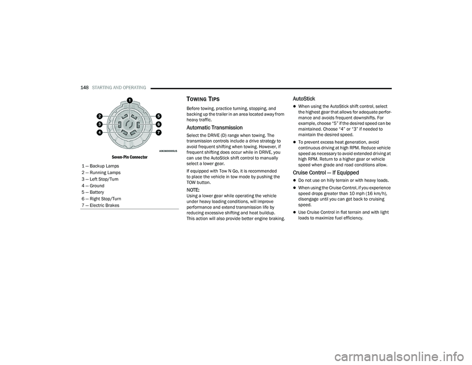
Seven-Pin Connector
TOWING TIPS
Before towing, practice turning, stopping, and
backing up the trailer in an area located away from
heavy traffic.
Automatic Transmission
Select the DRIVE (D) range when towing. The
transmission controls include a drive strategy to
avoid frequent shifting when towing. However, if
frequent shifting does occur while in DRIVE, you
can use the AutoStick shift control to manually
select a lower gear.
If equipped with Tow N Go, it is recommended
to place the vehicle in tow mode by pushing the
TOW button.
NOTE:Using a lower gear while operating the vehicle
under heavy loading conditions, will improve
performance and extend transmission life by
reducing excessive shifting and heat buildup.
This action will also provide better engine braking.
AutoStick
When using the AutoStick shift control, select
the highest gear that allows for adequate perfor -
mance and avoids frequent downshifts. For
example, choose “5” if the desired speed can be
maintained. Choose “4” or “3” if needed to
maintain the desired speed.
To prevent excess heat generation, avoid
continuous driving at high RPM. Reduce vehicle
speed as necessary to avoid extended driving at
high RPM. Return to a higher gear or vehicle
speed when grade and road conditions allow.
Cruise Control — If Equipped
Do not use on hilly terrain or with heavy loads.
When using the Cruise Control, if you experience
speed drops greater than 10 mph (16 km/h),
disengage until you can get back to cruising
speed.
Use Cruise Control in flat terrain and with light
loads to maximize fuel efficiency.
1 — Backup Lamps
2 — Running Lamps
3 — Left Stop/Turn
4 — Ground
5 — Battery
6 — Right Stop/Turn
7 — Electric Brakes
22_WD_OM_EN_USC_t.book Page 148
Page 157 of 332
STARTING AND OPERATING155
After Driving Off-Road
Off-road operation puts more stress on your
vehicle than does most on-road driving. After going
off-road, it is always a good idea to check for
damage. That way you can get any problems taken
care of right away and have your vehicle ready
when you need it.
Completely inspect the underbody of your
vehicle. Check tires, body structure, steering,
suspension, and exhaust system for damage.
Inspect the radiator for mud and debris and
clean as required.
Check threaded fasteners for looseness, partic -
ularly on the chassis, drivetrain components,
steering, and suspension. Retighten them, if
required, and torque to the values specified in
the Service Manual.
Check for accumulations of plants or brush.
These things could be a fire hazard. They might
hide damage to fuel lines, brake hoses, axle
pinion seals, and propeller shafts.
After extended operation in mud, sand, water, or
similar dirty conditions, have the radiator, fan,
brake rotors, wheels, brake linings, and axle
yokes inspected and cleaned as soon as
possible.If you experience unusual vibration after driving
in mud, slush or similar conditions, check the
wheels for impacted material. Impacted mate -
rial can cause a wheel imbalance and freeing
the wheels of it will correct the situation.
WARNING!
Abrasive material in any part of the brakes may
cause excessive wear or unpredictable braking.
You might not have full braking power when you
need it to prevent a collision. If you have been
operating your vehicle in dirty conditions, get
your brakes checked and cleaned as necessary.
4
22_WD_OM_EN_USC_t.book Page 155
Page 161 of 332
MULTIMEDIA159
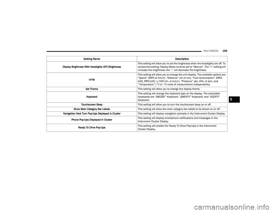
Display Brightness With Headlights OFF/Brightness This setting will allow you to set the brightness when the headlights are off. To
access this setting, Display Mode must be set to “Manual”. The “+” setting will
increase the brightness; the “-” will decrease the brightness.
Units This setting will allow you to change the unit display. The available options are
“Speed” (MPH or km/h), “Distance” (mi or km), “Fuel Consumption” (MPG
[US], MPG [UK], L/100 km, or km/L), “Pressure” (psi, kPa, or bar), and
“Temperature” (°C or °F) units of measurement independently.
Set Theme This setting will allow you to change the display theme.
Keyboard This setting will change the keyboard type on the display. The selectable
keyboards are “ABCDEF” Keyboard, “QWERTY” Keyboard, and “AZERTY”
Keyboard.
Touchscreen Beep This setting will allow you to turn the touchscreen beep on or off.
Show Main Category Bar Labels This setting will allow the main category bar labels to be shown on or off.
Navigation Next Turn Pop-Ups Displayed in Cluster This setting will display navigation prompts in the Instrument Cluster Display.
Phone Pop-Ups Displayed In Cluster This setting will display smartphone notifications and messages in the
Instrument Cluster Display.
Ready To Drive Pop-Ups This setting will enable the Ready To Drive Pop-Ups in the Instrument
Cluster Display.
Setting Name
Description
5
22_WD_OM_EN_USC_t.book Page 159
Page 162 of 332
160MULTIMEDIA
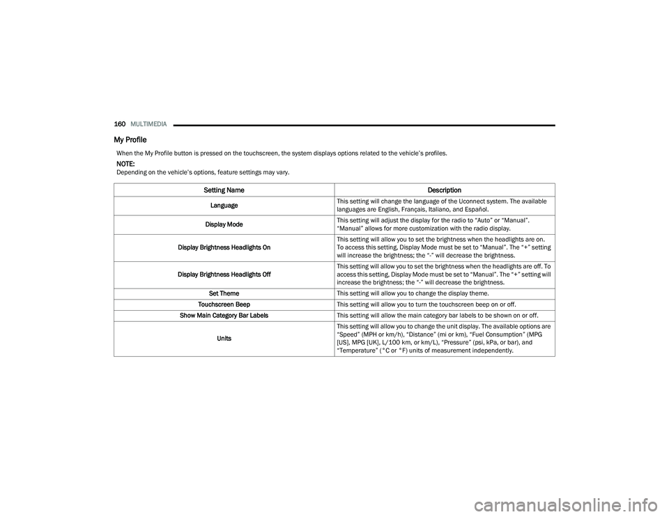
My Profile
When the My Profile button is pressed on the touchscreen, the system displays options related to the vehicle’s profiles.
NOTE:Depending on the vehicle’s options, feature settings may vary.
Setting Name Description
LanguageThis setting will change the language of the Uconnect system. The available
languages are English, Français, Italiano, and Español.
Display Mode This setting will adjust the display for the radio to “Auto” or “Manual”.
“Manual” allows for more customization with the radio display.
Display Brightness Headlights On This setting will allow you to set the brightness when the headlights are on.
To access this setting, Display Mode must be set to “Manual”. The “+” setting
will increase the brightness; the “-” will decrease the brightness.
Display Brightness Headlights Off This setting will allow you to set the brightness when the headlights are off. To
access this setting, Display Mode must be set to “Manual”. The “+” setting will
increase the brightness; the “-” will decrease the brightness.
Set Theme This setting will allow you to change the display theme.
Touchscreen Beep This setting will allow you to turn the touchscreen beep on or off.
Show Main Category Bar Labels This setting will allow the main category bar labels to be shown on or off.
Units This setting will allow you to change the unit display. The available options are
“Speed” (MPH or km/h), “Distance” (mi or km), “Fuel Consumption” (MPG
[US], MPG [UK], L/100 km, or km/L), “Pressure” (psi, kPa, or bar), and
“Temperature” (°C or °F) units of measurement independently.
22_WD_OM_EN_USC_t.book Page 160
Page 167 of 332
MULTIMEDIA165
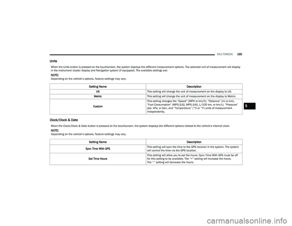
Units
Clock/Clock & Date
When the Units button is pressed on the touchscreen, the system displays the different measurement options. The selected unit of measurement will display
in the instrument cluster display and Navigation system (if equipped). The available settings are:
NOTE:Depending on the vehicle’s options, feature settings may vary.
Setting Name Description
USThis setting will change the unit of measurement on the display to US.
Metric This setting will change the unit of measurement on the display to Metric.
Custom This setting changes the “Speed” (MPH or km/h), “Distance” (mi or km),
“Fuel Consumption” (MPG [US], MPG [UK], L/100 km, or km/L), “Pressure”
(psi, kPa, or bar), and “Temperature” (°C or °F) units of measurement
independently.
When the Clock/Clock & Date button is pressed on the touchscreen, the system displays the different options related to the vehicle’s internal clock.
NOTE:Depending on the vehicle’s options, feature settings may vary.
Setting Name
Description
Sync Time With GPSThis setting will sync the time to the GPS receiver in the system. The system
will control the time via the GPS location.
Set Time Hours This setting will allow you to set the hours. Sync Time With GPS must be off
for this setting to be available. The “+” setting will increase the hours.
The “-” setting will decrease the hours.
5
22_WD_OM_EN_USC_t.book Page 165
Page 196 of 332
194SAFETY
(Continued)
For example, your vehicle has a recommended
cold (parked for more than three hours) tire
pressure of 33 psi (227 kPa). If the ambient
temperature is 68°F (20°C) and the measured tire
pressure is 28 psi (193 kPa), a temperature drop
to 20°F (-7°C) will decrease the tire pressure to
approximately 24 psi (165 kPa). This tire pressure
is sufficiently low enough to turn on the TPMS
Warning Light. Driving the vehicle may cause the
tire pressure to rise to approximately 28 psi
(193 kPa), but the TPMS Warning Light will still be
on. In this situation, the TPMS Warning Light will
turn off only after the tires have been inflated to
the vehicle’s recommended cold tire pressure
value.
NOTE:
The TPMS is not intended to replace normal tire
care and maintenance, or to provide warning of
a tire failure or condition.
The TPMS should not be used as a tire pressure
gauge while adjusting your tire pressure.
Driving on a significantly underinflated tire
causes the tire to overheat and can lead to tire
failure. Underinflation also reduces fuel effi
-
ciency and tire tread life, and may affect the
vehicle’s handling and stopping ability.
The TPMS is not a substitute for proper tire
maintenance, and it is the driver’s responsibility
to maintain correct tire pressure using an accu -
rate tire gauge, even if underinflation has not
reached the level to trigger illumination of the
TPMS Warning Light.
Seasonal temperature changes will affect tire
pressure, and the TPMS will monitor the actual
tire pressure in the tire.
The TPMS uses wireless technology with wheel
rim-mounted electronic sensors to monitor tire
pressure levels. Sensors, mounted to each wheel
as part of the valve stem, transmit tire pressure
readings to the receiver module.
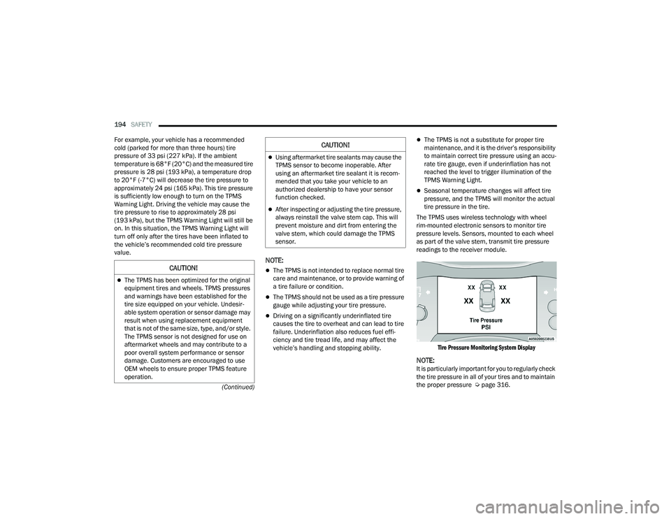
Tire Pressure Monitoring System Display
NOTE:It is particularly important for you to regularly check
the tire pressure in all of your tires and to maintain
the proper pressure Ú page 316.
CAUTION!
The TPMS has been optimized for the original
equipment tires and wheels. TPMS pressures
and warnings have been established for the
tire size equipped on your vehicle. Undesir -
able system operation or sensor damage may
result when using replacement equipment
that is not of the same size, type, and/or style.
The TPMS sensor is not designed for use on
aftermarket wheels and may contribute to a
poor overall system performance or sensor
damage. Customers are encouraged to use
OEM wheels to ensure proper TPMS feature
operation.
Using aftermarket tire sealants may cause the
TPMS sensor to become inoperable. After
using an aftermarket tire sealant it is recom -
mended that you take your vehicle to an
authorized dealership to have your sensor
function checked.
After inspecting or adjusting the tire pressure,
always reinstall the valve stem cap. This will
prevent moisture and dirt from entering the
valve stem, which could damage the TPMS
sensor.
CAUTION!
22_WD_OM_EN_USC_t.book Page 194
Page 216 of 332
214SAFETY
As the air bags deflate, you may see some
smoke-like particles. The particles are a normal
by-product of the process that generates the
non-toxic gas used for air bag inflation. These
airborne particles may irritate the skin, eyes,
nose, or throat. If you have skin or eye irritation,
rinse the area with cool water. For nose or throat
irritation, move to fresh air. If the irritation
continues, see your doctor. If these particles
settle on your clothing, follow the garment
manufacturer’s instructions for cleaning.
Do not drive your vehicle after the air bags have
deployed. If you are involved in another collision,
the air bags will not be in place to protect you.
NOTE:
Air bag covers may not be obvious in the interior
trim, but they will open during air bag deploy -
ment.
After any collision, the vehicle should be taken
to an authorized dealer immediately.
Enhanced Accident Response System
In the event of an impact, if the communication
network remains intact, and the power remains
intact, depending on the nature of the event, the
Occupant Restraint Controller (ORC) will determine
whether to have the Enhanced Accident Response
System perform the following functions:
Cut off fuel to the engine (if equipped).
Cut off battery power to the electric motor
(if equipped).
Flash hazard lights as long as the battery has
power.
Turn on the interior lights, which remain on as
long as the battery has power or for 15 minutes
from the intervention of the Enhanced Accident
Response System.
Unlock the power door locks.
Your vehicle may also be designed to perform any
of these other functions in response to the
Enhanced Accident Response System:
Turn off the Fuel Filter Heater, Turn off the HVAC
Blower Motor, Close the HVAC Circulation Door
Cut off battery power to the:
Engine
Electric Motor (if equipped)
Electric power steering
Brake booster
Electric park brake
Automatic transmission gear selector
Horn
Front wiper
Headlamp washer pump (if equipped)
NOTE:After an accident, remember to cycle the ignition to
the STOP (OFF/LOCK) position and remove the key
from the ignition switch to avoid draining the
battery. Carefully check the vehicle for fuel leaks in
the engine compartment and on the ground near
the engine compartment and fuel tank before
resetting the system and starting the engine. If
there are no fuel leaks or damage to the vehicle
electrical devices (e.g. headlights) after an
accident, reset the system by following the
procedure described below. If you have any doubt,
contact an authorized dealer.
Enhanced Accident Response System
Reset Procedure
In order to reset the Enhanced Accident Response
System functions after an event, the ignition switch
must be changed from ignition START or ON/RUN
to ignition OFF. Carefully check the vehicle for fuel
leaks in the engine compartment and on the
ground near the engine compartment and fuel
tank before resetting the system and starting the
engine.
WARNING!
Deployed air bags and seat belt pretensioners
cannot protect you in another collision. Have the
air bags, seat belt pretensioners, and the seat belt
retractor assemblies replaced by an authorized
dealer immediately. Also, have the Occupant
Restraint Controller System serviced as well.
22_WD_OM_EN_USC_t.book Page 214