tow DODGE DURANGO 2023 Owner's Guide
[x] Cancel search | Manufacturer: DODGE, Model Year: 2023, Model line: DURANGO, Model: DODGE DURANGO 2023Pages: 328, PDF Size: 13.82 MB
Page 112 of 328
110STARTING AND OPERATING
When operating your vehicle in AWD LOW, the
engine speed is approximately three times that of
the AWD AUTO position at a given road speed. Take
care not to overspeed the engine and do not
exceed 25 mph (40 km/h).
Proper operation of all-wheel drive vehicles
depends on tires of equal size, type and
circumference on each wheel. Any difference in
tire size can cause damage to the transfer case.
Because all-wheel drive provides improved
traction, there is a tendency to exceed safe turning
and stopping speeds. Do not go faster than road
conditions permit.
For additional information on the appropriate use
of each transfer case position, see the following:
AWD LOW
All-Wheel Drive Low Range – This range provides
low speed all-wheel drive. Locks the front and rear
driveshafts together forcing the front and rear
wheels to rotate at the same speed. Additional
traction and maximum pulling power for loose,
slippery road surfaces only. Do not exceed 25 mph
(40 km/h).
N (Neutral)
This range disengages both the front and rear
driveshafts from the powertrain. To be used for flat
towing behind another vehicle Ú page 146.
SHIFTING PROCEDURE
NOTE:
If any of the requirements to select a new
transfer case position have not been met, the
transfer case will not shift. The position indi -
cator light for the previous position will remain
on and the newly selected position indicator
light will continue to flash until all the require -
ments for the selected position have been met.
To retry a shift: return the control switch back to
the original position, make certain all shift
requirements have been met, wait five seconds
and try the shift again.
If all the requirements to select a new transfer
case position have been met, the current posi -
tion indicator light will turn off, the selected posi -
tion indicator light will flash until the transfer case completes the shift. When the shift is
complete, the position indicator light for the
selected position will stop flashing and remain
on.
AWD AUTO To AWD LOW
NOTE:When shifting into or out of AWD LOW some gear
noise may be heard. This noise is normal and is not
detrimental to the vehicle or occupants.
Shifting can be performed with the vehicle rolling 2
to 3 mph (3 to 5 km/h) or completely stopped. Use
either of the following procedures:
Preferred Procedure
1. With the engine running, slow the vehicle to 2
to 3 mph (3 to 5 km/h).
2. Shift the transmission into NEUTRAL.
3. While still rolling, push the AWD LOW control switch.
4. After the AWD LOW position indicator light is on (not flashing), shift the transmission back into
gear.
Alternate Procedure
1. Bring the vehicle to complete stop.
2. With the ignition in ON/RUN position and engine running, shift the transmission to
NEUTRAL.
3. Push the AWD LOW control switch.
WARNING!
You or others could be injured or killed if you
leave the vehicle unattended with the transfer
case in the N (Neutral) position without first fully
engaging the parking brake. The transfer case N
(Neutral) position disengages both the front and
rear drive shafts from the powertrain and will
allow the vehicle to roll, even if the transmission
is in PARK. The parking brake should always be
applied when the driver is not in the vehicle.
23_WD_OM_EN_USC_t.book Page 110
Page 113 of 328
STARTING AND OPERATING111
4. After the AWD LOW position indicator light is on (not flashing), shift the transmission back into
gear.
NOTE:
If steps 1 or 2 of either the “Preferred” or “Alter -
nate Procedure” are not satisfied prior to
attempting the shift or if they no longer are
being met while the shift attempt is in process,
the desired position indicator light will flash
continuously while the original position indicator
light is on, until all requirements have been met.
The ignition switch must be in the ON/RUN posi -
tion for a shift to take place and for the position
indicator lights to be operable. If the ignition
switch is not in the ON/RUN position, then the
shift will not take place and no position indicator
lights will be on or flashing.
N (Neutral) Shift Procedure
For information regarding the transfer case N
(Neutral) shift procedure Ú page 148.
TOW N GO — IF EQUIPPED
Tow N Go combines the capabilities of the vehicle
control systems, along with driver input, to provide
optimum performance for road conditions.
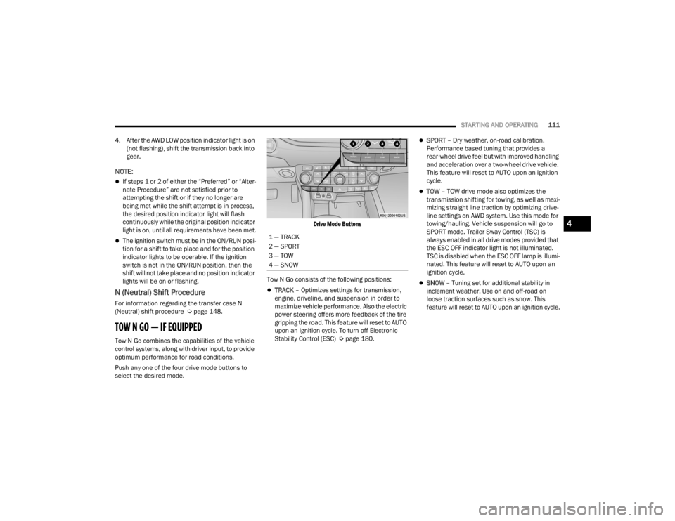
Push any one of the four drive mode buttons to
select the desired mode.
Drive Mode Buttons
Tow N Go consists of the following positions:
TRACK – Optimizes settings for transmission,
engine, driveline, and suspension in order to
maximize vehicle performance. Also the electric
power steering offers more feedback of the tire
gripping the road. This feature will reset to AUTO
upon an ignition cycle. To turn off Electronic
Stability Control (ESC) Ú page 180.
SPORT – Dry weather, on-road calibration.
Performance based tuning that provides a
rear-wheel drive feel but with improved handling
and acceleration over a two-wheel drive vehicle.
This feature will reset to AUTO upon an ignition
cycle.
TOW – TOW drive mode also optimizes the
transmission shifting for towing, as well as maxi -
mizing straight line traction by optimizing drive -
line settings on AWD system. Use this mode for
towing/hauling. Vehicle suspension will go to
SPORT mode. Trailer Sway Control (TSC) is
always enabled in all drive modes provided that
the ESC OFF indicator light is not illuminated.
TSC is disabled when the ESC OFF lamp is illumi -
nated. This feature will reset to AUTO upon an
ignition cycle.
SNOW – Tuning set for additional stability in
inclement weather. Use on and off-road on
loose traction surfaces such as snow. This
feature will reset to AUTO upon an ignition cycle.
1 — TRACK
2 — SPORT
3 — TOW
4 — SNOW
4
23_WD_OM_EN_USC_t.book Page 111
Page 120 of 328
118STARTING AND OPERATING
Adaptive Cruise Control (ACC) Operation
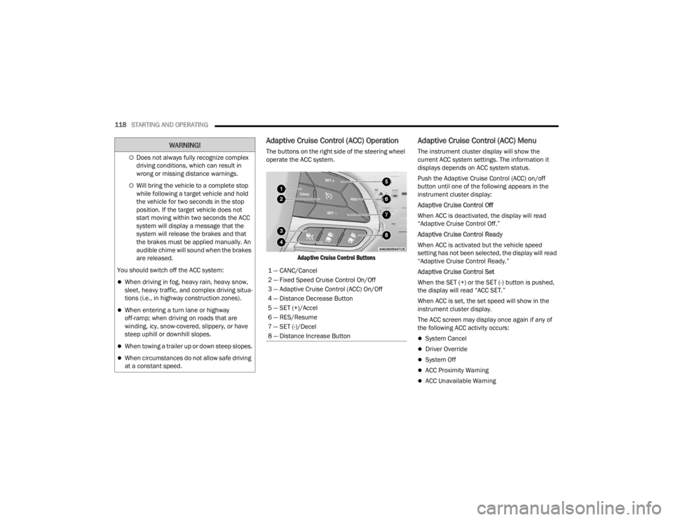
The buttons on the right side of the steering wheel
operate the ACC system.
Adaptive Cruise Control Buttons
Adaptive Cruise Control (ACC) Menu
The instrument cluster display will show the
current ACC system settings. The information it
displays depends on ACC system status.
Push the Adaptive Cruise Control (ACC) on/off
button until one of the following appears in the
instrument cluster display:
Adaptive Cruise Control Off
When ACC is deactivated, the display will read
“Adaptive Cruise Control Off.”
Adaptive Cruise Control Ready
When ACC is activated but the vehicle speed
setting has not been selected, the display will read
“Adaptive Cruise Control Ready.”
Adaptive Cruise Control Set
When the SET (+) or the SET (-) button is pushed,
the display will read “ACC SET.”
When ACC is set, the set speed will show in the
instrument cluster display.
The ACC screen may display once again if any of
the following ACC activity occurs:
System Cancel
Driver Override
System Off
ACC Proximity Warning
ACC Unavailable Warning
Does not always fully recognize complex
driving conditions, which can result in
wrong or missing distance warnings.
Will bring the vehicle to a complete stop
while following a target vehicle and hold
the vehicle for two seconds in the stop
position. If the target vehicle does not
start moving within two seconds the ACC
system will display a message that the
system will release the brakes and that
the brakes must be applied manually. An
audible chime will sound when the brakes
are released.
You should switch off the ACC system:
When driving in fog, heavy rain, heavy snow,
sleet, heavy traffic, and complex driving situa -
tions (i.e., in highway construction zones).
When entering a turn lane or highway
off-ramp; when driving on roads that are
winding, icy, snow-covered, slippery, or have
steep uphill or downhill slopes.
When towing a trailer up or down steep slopes.
When circumstances do not allow safe driving
at a constant speed.
WARNING!
1 — CANC/Cancel
2 — Fixed Speed Cruise Control On/Off
3 — Adaptive Cruise Control (ACC) On/Off
4 — Distance Decrease Button
5 — SET (+)/Accel
6 — RES/Resume
7 — SET (-)/Decel
8 — Distance Increase Button
23_WD_OM_EN_USC_t.book Page 118
Page 126 of 328
124STARTING AND OPERATING
SERVICE ACC/FCW WARNING
If the system turns off, and the instrument cluster
display reads “ACC/FCW Unavailable Service
Required” or “Cruise/FCW Unavailable Service
Required”, there may be an internal system fault or
a temporary malfunction that limits ACC
functionality. Although the vehicle is still drivable
under normal conditions, ACC will be temporarily
unavailable. If this occurs, try activating ACC again
later, following an ignition cycle. If the problem
persists, see an authorized dealer.
Precautions While Driving With ACC
In certain driving situations, ACC may have
detection issues. In these cases, ACC may brake
late or unexpectedly. The driver needs to stay alert
and may need to intervene. The following are
examples of these types of situations:
TOWING A TRAILER
ACC while towing a trailer is recommended only
with an Integrated Trailer Brake Controller.
Aftermarket trailer brake controllers will not
activate the trailer brakes when ACC is braking.
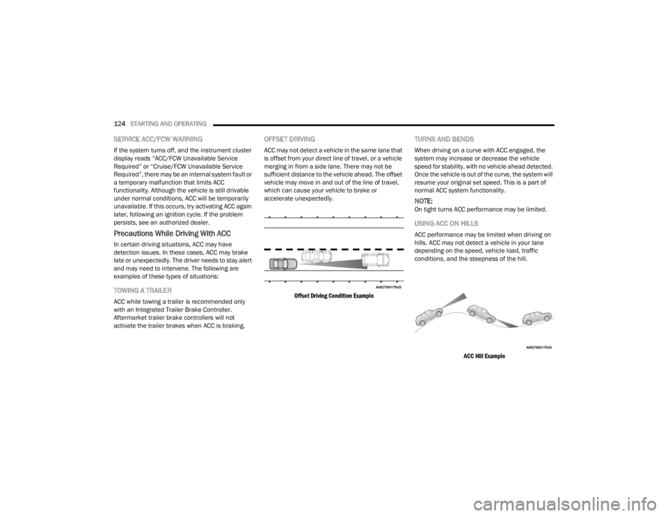
OFFSET DRIVING
ACC may not detect a vehicle in the same lane that
is offset from your direct line of travel, or a vehicle
merging in from a side lane. There may not be
sufficient distance to the vehicle ahead. The offset
vehicle may move in and out of the line of travel,
which can cause your vehicle to brake or
accelerate unexpectedly.
Offset Driving Condition Example
TURNS AND BENDS
When driving on a curve with ACC engaged, the
system may increase or decrease the vehicle
speed for stability, with no vehicle ahead detected.
Once the vehicle is out of the curve, the system will
resume your original set speed. This is a part of
normal ACC system functionality.
NOTE:On tight turns ACC performance may be limited.
USING ACC ON HILLS
ACC performance may be limited when driving on
hills. ACC may not detect a vehicle in your lane
depending on the speed, vehicle load, traffic
conditions, and the steepness of the hill.
ACC Hill Example
23_WD_OM_EN_USC_t.book Page 124
Page 128 of 328
126STARTING AND OPERATING
Automatic emergency braking is not available if
the vehicle is in 4WD Low.
Automatic emergency braking will not be avail -
able if there is a faulted condition detected with
the ParkSense Park Assist system or the
Braking System Module.
The automatic emergency braking function may
only be applied if the vehicle deceleration is not
enough to avoid colliding with a detected
obstacle.
The automatic emergency braking function may
not be applied fast enough for obstacles that
move toward the rear of the vehicle from the left
and/or right sides.
The automatic emergency braking function can
be enabled/disabled from the Customer
Programmable Features section of the
Uconnect system.
ParkSense will retain its last known configura -
tion state for the automatic emergency braking
function through ignition cycles.
The rear automatic emergency braking function is
intended to assist the driver in avoiding possible
collisions with detected obstacles when backing
up in REVERSE gear.
NOTE:
The rear automatic emergency braking system
is for emergency braking to avoid an imminent collision. It is designed to assist the driver and
not to substitute the driver.
The driver must stay in full control of the
vehicle's acceleration and braking and is
responsible for the vehicle's movements.
For limitations of this system and
recommendations, see Ú page 130.
ParkSense will retain the last system state
(enabled or disabled) from the last ignition cycle
when the ignition is changed to the ON/RUN
position.
ParkSense can be active only when the gear
selector is in REVERSE or DRIVE. If ParkSense is
enabled at one of these gear selector positions,
the system will remain active until the vehicle
speed is increased to approximately 7 mph
(11 km/h) or above. The system will become active
again if the vehicle speed is decreased to speeds
less than approximately 6 mph (9 km/h). A display
warning will appear in the instrument cluster
display if the vehicle is in REVERSE and the speed
exceeds 7 mph (11 km/h).
PARKSENSE SENSORS
Six ParkSense sensors located in the front fascia/
bumper (if equipped) and six ParkSense sensors
(four when vehicle is not equipped with front
sensors) located in the rear fascia/bumper,
monitor the area in front and behind the vehicle
that is within the sensors’ field of view. The front sensors detect obstacles from approximately
12 inches (30 cm) up to 47 inches (120 cm) from
the front fascia/bumper. The rear sensors can
detect obstacles from approximately 12 inches
(30 cm) up to 79 inches (200 cm) from the rear
fascia/bumper. These distances depend on the
location, type and orientation of the obstacle in the
horizontal direction.
PARKSENSE DISPLAY
The warning display will turn on indicating the
system status when the vehicle is in REVERSE or
when the vehicle is in DRIVE and an obstacle has
been detected.
The system will indicate a detected obstacle by
showing a single arc in the left and/or right front or
rear regions based on the object’s distance and
location relative to the vehicle.
If an object is detected in the left and/or right rear
region, the display will show a single arc in the left
and/or right rear region and the system will
produce a tone. As the vehicle moves closer to the
object, the display will show the single arc moving
closer to the vehicle and the tone will change from
a single 1/2 second tone to slow, to fast, to
continuous.
23_WD_OM_EN_USC_t.book Page 126
Page 131 of 328
STARTING AND OPERATING129
NOTE:If the radio is on, ParkSense will reduce the volume
of the radio when the system is sounding an audio
tone.
Front Park Assist Audible Alerts
ParkSense will turn off the Front Park Assist
audible alert (chime) after approximately three
seconds when an obstacle has been detected, the
vehicle is stationary, and brake pedal is applied.
Adjustable Chime Volume Settings
Front and Rear chime volume settings can be
selected from the Uconnect system
Úpage 153.
The chime volume settings include low,
medium, and high.
ParkSense will retain its last known configura -
tion state through ignition cycles.
PARKSENSE WARNING DISPLAY
The ParkSense Warning screen is located within
the instrument cluster display Ú page 79. It
provides visual warnings to indicate the distance
between the rear fascia/bumper and/or front
fascia/bumper and the detected obstacle.
The ParkSense Warning screen will only be
displayed if Sound and Display is selected from the
Customer Programmable Features section of the
Uconnect system Ú page 153.
ENABLING AND DISABLING PARKSENSE
ParkSense can be enabled and disabled
with the ParkSense switch.
When the ParkSense switch is pressed to
disable the system, the LED light on the switch will
be illuminated.
When the ParkSense switch is pushed to disable
the system, the instrument cluster will display the
“PARKSENSE OFF” message for approximately five
seconds. When the gear selector is moved to
REVERSE and the system is disabled, the
instrument cluster display will display the
“PARKSENSE OFF” message for as long as the
vehicle is in REVERSE.
NOTE:When ParkSense is disabled and the gear selector
is moved to the DRIVE position, no warning
message will be displayed.
The ParkSense switch LED will be on when
ParkSense is disabled or requires service. The
ParkSense switch LED will be off when the system
is enabled. When the system is disabled due to a
fault, the LED light on the switch will be
illuminated. If the driver tries to press the
ParkSense switch to activate the system, the
button will blink for five seconds to show the
request was received, but cannot be fulfilled.
OPERATION WITH A TRAILER
For vehicles equipped with an Integrated Trailer
Brake Module (ITBM), the operation of the rear
sensors is automatically deactivated when the
trailer's electric plug is inserted in the vehicle's tow
hook socket. The front system is still functional,
and the arcs will be overlaid with a “Trailer”
message. The rear sensors are automatically
reactivated when the trailer's cable plug is
removed.
When the vehicle is connected to a trailer, the
instrument cluster display will show the "Rear
ParkSense Unavailable Trailer Connected"
message in the following situations:
For five seconds at vehicle start up
For five seconds when the ParkSense button is
pushed, as long as an object is not detected in
the front
As long as the vehicle is in REVERSE (vehicle
graphic displayed with a trailer overlay)
NOTE:
For more information on the Integrated Trailer
Brake Module, see Ú page 142.
For vehicles not equipped with ITBM, the
automatic braking may falsely be applied if a trailer
is hooked up, and Park Assist is not manually
deactivated. It is also possible, the trailer may be
mistaken as a close object.
4
23_WD_OM_EN_USC_t.book Page 129
Page 132 of 328
130STARTING AND OPERATING
SERVICE THE PARKSENSE PARK ASSIST
S
YSTEM
During vehicle start up, when the ParkSense
System has detected a fault condition, the
instrument cluster will actuate a single chime,
once per ignition cycle, and it will display the
"PARKSENSE UNAVAILABLE WIPE REAR
SENSORS", "PARKSENSE UNAVAILABLE WIPE
FRONT SENSORS", or the "PARKSENSE
UNAVAILABLE SERVICE REQUIRED" message for
five seconds.
When the gear selector is moved to REVERSE and
the system has detected a fault condition, the
instrument cluster display will display a "PARKSENSE UNAVAILABLE WIPE REAR
SENSORS", "PARKSENSE UNAVAILABLE WIPE
FRONT SENSORS" or "PARKSENSE UNAVAILABLE
SERVICE REQUIRED" pop-up message for five
seconds. After five seconds, a vehicle graphic will
be displayed with "UNAVAILABLE" at either the
front or rear sensor location depending on where
the fault is detected. The system will continue to
provide arc alerts for the side that is functioning
properly. These arc alerts will interrupt the
"PARKSENSE UNAVAILABLE WIPE REAR
SENSORS", "PARKSENSE UNAVAILABLE WIPE
FRONT SENSORS", or "PARKSENSE UNAVAILABLE
SERVICE REQUIRED" messages if an object is
detected within the five second pop-up duration.
The vehicle graphic will remain displayed for as
long as the vehicle is in REVERSE.
If "PARKSENSE UNAVAILABLE WIPE REAR
SENSORS" or "PARKSENSE UNAVAILABLE WIPE
FRONT SENSORS" appears in the instrument
cluster display make sure the outer surface and
the underside of the rear fascia/bumper and/or
front fascia/bumper is clean and clear of snow,
ice, mud, dirt or other obstruction and then cycle
the ignition. If the message continues to appear
see an authorized dealer.
If the "PARKSENSE UNAVAILABLE SERVICE
REQUIRED" message appears in the instrument
cluster display, see an authorized dealer.
CLEANING THE PARKSENSE SYSTEM
Clean the ParkSense sensors with water, car wash
soap and a soft cloth. Do not use rough or hard
cloths. Do not scratch or poke the sensors.
PARKSENSE SYSTEM USAGE
P
RECAUTIONS
Ensure that the front and rear fascias/bumpers
are free of snow, ice, mud, dirt and debris to
keep the ParkSense system operating properly.
Jackhammers, large trucks, and other vibra -
tions could affect the performance of
ParkSense.
When you turn ParkSense off, the instrument
cluster will display “PARKSENSE OFF.” Further -
more, once you turn ParkSense off, it remains
off until you turn it on again, even if you cycle the
ignition.
When you move the gear selector to the
REVERSE position and ParkSense is turned off,
the instrument cluster will display “PARKSENSE
OFF” for as long as the vehicle is in REVERSE.
ParkSense, when on, will reduce the volume of
the radio when it is sounding a tone.
Clean the ParkSense sensors regularly, taking
care not to scratch or damage them. The
sensors must not be covered with ice, snow,
slush, mud, dirt or debris. Failure to do so can
WARNING!
Before using ParkSense, it is strongly
recommended that the ball mount and hitch ball
assembly be disconnected from the vehicle
when the vehicle is not used for towing. Failure
to do so can result in injury or damage to
vehicles or obstacles because the hitch ball will
be much closer to the obstacle than the rear
fascia when the vehicle sounds the continuous
tone. Also, the sensors could detect the ball
mount and hitch ball assembly, depending on its
size and shape, giving a false indication that an
obstacle is behind the vehicle.
23_WD_OM_EN_USC_t.book Page 130
Page 133 of 328
STARTING AND OPERATING131
(Continued)
result in the system not working properly. The
ParkSense system might not detect an obstacle
behind or in front of the fascia/bumper, or it
could provide a false indication that an obstacle
is behind or in front of the fascia/bumper.
Use the ParkSense switch to turn the ParkSense
system off if objects such as bicycle carriers,
trailer hitches, etc. are placed within 12 inches
(30 cm) of the rear fascia/bumper. Failure to do
so can result in the system misinterpreting a
close object as a sensor problem, causing the
“PARKSENSE UNAVAILABLE SERVICE
REQUIRED” message to be displayed in the
instrument cluster.
ParkSense should be disabled when the liftgate
is in the open position. An opened liftgate could
provide a false indication that an obstacle is
behind the vehicle.
LANESENSE — IF EQUIPPED
LANESENSE OPERATION
The LaneSense system is operational at speeds
above 37 mph (60 km/h) and below 112 mph
(180 km/h). The LaneSense system uses a
forward looking camera to detect lane markings
and measure vehicle position within the lane
boundaries.
When both lane markings are detected and the
driver drifts out of the lane (no turn signal applied),
the LaneSense system provides a haptic warning
in the form of torque applied to the steering wheel
to prompt the driver to remain within the lane
boundaries. If the driver continues to drift out of
the lane, the LaneSense system provides a visual
warning through the instrument cluster display to
prompt the driver to remain within the lane
boundaries.
The driver may manually override the haptic
warning by applying force to the steering wheel at
any time.
When only a single lane marking is detected and
the driver drifts across the lane marking (no turn
signal applied), the LaneSense system provides
visual warnings through the instrument cluster
display to prompt the driver to remain within the
lane. When only a single lane marking is detected,
a haptic or a torque warning will not be provided.
WARNING!
Drivers must be careful when backing up even
when using ParkSense. Always check carefully
behind your vehicle, look behind you, and be
sure to check for pedestrians, animals, other
vehicles, obstructions, and blind spots before
backing up. You are responsible for safety and
must continue to pay attention to your
surroundings. Failure to do so can result in
serious injury or death.
Before using ParkSense, it is strongly recom
-
mended that the ball mount and hitch ball
assembly be disconnected from the vehicle
when the vehicle is not used for towing.
Failure to do so can result in injury or damage
to vehicles or obstacles because the hitch ball
will be much closer to the obstacle than the
rear fascia when the vehicle sounds the
continuous tone. Also, the sensors could
detect the ball mount and hitch ball assembly,
depending on its size and shape, giving a false
indication that an obstacle is behind the
vehicle.
CAUTION!
ParkSense is only a parking aid and it is
unable to recognize every obstacle, including
small obstacles. Parking curbs might be
temporarily detected or not detected at all.
Obstacles located above or below the sensors
will not be detected when they are in close
proximity.
The vehicle must be driven slowly when using
ParkSense in order to be able to stop in time
when an obstacle is detected. It is recom -
mended that the driver looks over his/her
shoulder when using ParkSense.
WARNING!
4
23_WD_OM_EN_USC_t.book Page 131
Page 138 of 328
136STARTING AND OPERATING
VEHICLE LOADING
CERTIFICATION LABEL
As required by National Highway Traffic Safety
Administration regulations, your vehicle has a
certification label affixed to the driver's side door or
pillar.
This label contains the month and year of
manufacture, Gross Vehicle Weight Rating
(GVWR), front and rear Gross Axle Weight Rating
(GAWR), and Vehicle Identification Number (VIN). A
Month-Day-Hour (MDH) number is included on this
label and indicates the Month, Day and Hour of
manufacture. The bar code that appears on the
bottom of the label is your VIN.
Gross Vehicle Weight Rating (GVWR)
The GVWR is the total permissible weight of your
vehicle including driver, passengers, vehicle,
options and cargo. The label also specifies
maximum capacities of front and rear (GAWR).
Total load must be limited so GVWR and front and
rear GAWR are not exceeded.
Payload
The payload of a vehicle is defined as the allowable
load weight a truck can carry, including the weight
of the driver, all passengers, options and cargo.
Gross Axle Weight Rating (GAWR)
The GAWR is the maximum permissible load on the
front and rear axles. The load must be distributed
in the cargo area so that the GAWR of each axle is
not exceeded.
Each axle GAWR is determined by the components
in the system with the lowest load carrying capacity
(axle, springs, tires or wheels). Heavier axles or
suspension components sometimes specified by
purchasers for increased durability does not
necessarily increase the vehicle's GVWR.
Tire Size
The tire size on the Vehicle Certification Label
represents the actual tire size on your vehicle.
Replacement tires must be equal to the load
capacity of this tire size.
Rim Size
This is the rim size that is appropriate for the tire
size listed.
Inflation Pressure
This is the cold tire inflation pressure for your
vehicle for all loading conditions up to full GAWR.
Curb Weight
The curb weight of a vehicle is defined as the total
weight of the vehicle with all fluids, including
vehicle fuel, at full capacity conditions, and with no
occupants or cargo loaded into the vehicle. The front and rear curb weight values are determined
by weighing your vehicle on a commercial scale
before any occupants or cargo are added.
Loading
The actual total weight and the weight of the front
and rear of your vehicle at the ground can best be
determined by weighing it when it is loaded and
ready for operation.
The entire vehicle should first be weighed on a
commercial scale to ensure that the GVWR has not
been exceeded. The weight on the front and rear of
the vehicle should then be determined separately
to be sure that the load is properly distributed over
the front and rear axle. Weighing the vehicle may
show that the GAWR of either the front or rear axles
has been exceeded but the total load is within the
specified GVWR and maximum Payload. If so,
weight must be shifted from front to rear or rear to
front as appropriate until the specified weight
limitations are met. Store the heavier items down
low and be sure that the weight is distributed
equally. Stow all loose items securely before
driving.
Improper weight distributions can have an adverse
effect on the way your vehicle steers and handles
and the way the brakes operate.
23_WD_OM_EN_USC_t.book Page 136
Page 139 of 328
STARTING AND OPERATING137
TRAILER TOWING
In this section you will find safety tips and
information on limits to the type of towing you can
reasonably do with your vehicle. Before towing a
trailer, carefully review this information to tow your
load as efficiently and safely as possible.
To maintain the New Vehicle Limited Warranty
coverage, follow the requirements and
recommendations in this manual concerning
vehicles used for trailer towing.
COMMON TOWING DEFINITIONS
The following trailer towing related definitions will
assist you in understanding the following
information:
Gross Vehicle Weight Rating (GVWR)
The GVWR is the total allowable weight of your
vehicle. This includes driver, passengers, cargo
and tongue weight. The total load must be limited
so that you do not exceed the GVWR Ú page 136.
Gross Trailer Weight (GTW)
The GTW is the weight of the trailer plus the weight
of all cargo, consumables and equipment
(permanent or temporary) loaded in or on the
trailer in its "loaded and ready for operation"
condition.
The recommended way to measure GTW is to put
your fully loaded trailer on a vehicle scale. The
entire weight of the trailer must be supported by
the scale.
Gross Combination Weight Rating (GCWR)
The GCWR is the total allowable weight of your
vehicle and trailer when weighed in combination.
Gross Axle Weight Rating (GAWR)
The GAWR is the maximum capacity of the front
and rear axles. Distribute the load over the front
and rear axles evenly. Make sure that you do not
exceed either front or rear GAWR Úpage 136.
Tongue Weight (TW)
The TW is the downward force exerted on the hitch
ball by the trailer. You must consider this as part of
the load on your vehicle.
Trailer Frontal Area
The frontal area is the maximum height multiplied
by the maximum width of the front of a trailer.
Trailer Sway Control (TSC)
The TSC can be a mechanical telescoping link that
can be installed between the hitch receiver and the
trailer tongue that typically provides adjustable
friction associated with the telescoping motion to
dampen any unwanted trailer swaying motions
while traveling.
If equipped, the electronic TSC recognizes a
swaying trailer and automatically applies individual
wheel brakes and/or reduces engine power to
attempt to eliminate the trailer sway.
WARNING!
Do not load your vehicle any heavier than the
GVWR, maximum payload or the maximum front
and rear GAWR. If you do, parts on your vehicle
can break, or it can change the way your vehicle
handles. This could cause you to lose control.
Overloading can shorten the life of your vehicle.
WARNING!
If the gross trailer weight is 5,000 lb (2,267 kg)
or more, it is recommended to use a
weight-distributing hitch to ensure stable
handling of your vehicle. If you use a standard
weight-carrying hitch, you could lose control of
your vehicle and cause a collision.
WARNING!
It is important that you do not exceed the
maximum front or rear GAWR. A dangerous
driving condition can result if either rating is
exceeded. You could lose control of the vehicle
and have a collision.
4
23_WD_OM_EN_USC_t.book Page 137