ESP DODGE HORNET 2023 Owner's Guide
[x] Cancel search | Manufacturer: DODGE, Model Year: 2023, Model line: HORNET, Model: DODGE HORNET 2023Pages: 288, PDF Size: 14.2 MB
Page 158 of 288
156SAFETY
(Continued)
Electronic Stability Control (ESC)
ESC enhances directional control and stability of the
vehicle under various driving conditions. ESC corrects for
oversteering or understeering of the vehicle by applying
the brake of the appropriate wheel(s) to counteract these
conditions. Engine power may also be reduced to help the
vehicle maintain the desired path.
Oversteer — when the vehicle is turning more than
appropriate for the steering wheel position.
Understeer — when the vehicle is turning less than
appropriate for the steering wheel position.
ESC uses sensors in the vehicle to determine the vehicle
path intended by the driver and compares it to the actual
path of the vehicle. When the actual path does not match
the intended path, ESC applies the brake of the
appropriate wheel to assist in counteracting the oversteer
or understeer condition. The ESC Activation/Malfunction Indicator Light located in
the instrument cluster will start to flash as soon as the ESC
system becomes active. The ESC Activation/Malfunction
Indicator Light also flashes when the TCS is active. If the
ESC Activation/Malfunction Indicator Light begins to flash
during acceleration, ease up on the accelerator and apply
as little throttle as possible. Be sure to adapt your speed
and driving to the prevailing road conditions.
ESC Operating Modes
Depending upon model and mode of operation, the
ESC system may have multiple operating modes.
ESC On
This is the normal operating mode for the ESC. Whenever
the vehicle is started, the ESC system will be in this mode.
This mode should be used for most driving conditions.
Alternate ESC modes should only be used for specific
reasons as noted in the following paragraphs.
WARNING!
Many factors, such as vehicle loading, road conditions
and driving conditions, influence the chance that wheel
lift or rollover may occur. ERM cannot prevent all wheel
lift or rollovers, especially those that involve leaving the
roadway or striking objects or other vehicles. The
capabilities of an ERM-equipped vehicle must never be
exploited in a reckless or dangerous manner which could
jeopardize the user's safety or the safety of others.
WARNING!
Electronic Stability Control (ESC) cannot prevent the
natural laws of physics from acting on the vehicle,
nor can it increase the traction afforded by prevailing
road conditions. ESC cannot prevent accidents,
including those resulting from excessive speed in
turns, driving on very slippery surfaces, or hydro -
planing. ESC also cannot prevent accidents resulting
from loss of vehicle control due to inappropriate
driver input for the conditions. Only a safe, attentive,
and skillful driver can prevent accidents. The capabil -
ities of an ESC equipped vehicle must never be
exploited in a reckless or dangerous manner which
could jeopardize the user’s safety or the safety of
others.
Vehicle modifications, or failure to properly maintain
your vehicle, may change the handling characteris -
tics of your vehicle, and may negatively affect the
performance of the ESC system. Changes to the
steering system, suspension, braking system, tire
type and size or wheel size may adversely affect ESC
performance. Improperly inflated and unevenly worn
tires may also degrade ESC performance. Any vehicle
modification or poor vehicle maintenance that
reduces the effectiveness of the ESC system can
increase the risk of loss of vehicle control, vehicle
rollover, personal injury and death.
WARNING!
23_GG_OM_EN_USC_t.book Page 156
Page 160 of 288
158SAFETY
Hill Start Assist (HSA)
HSA is designed to mitigate roll back from a complete stop
while on an incline. If the driver releases the brake while
stopped on an incline, HSA will continue to hold the brake
pressure for a short period. If the driver does not apply the
throttle before this time expires, the system will release
brake pressure and the vehicle will roll down the hill as
normal.
The following conditions must be met in order for HSA to
activate:
The feature must be enabled.
The vehicle must be stopped.
The parking brake must be off.
The driver’s door must be closed.
The vehicle must be on a sufficient grade.
The gear selection must match vehicle uphill direction
(i.e., vehicle facing uphill is in forward gear; vehicle
backing uphill is in REVERSE gear).
HSA will work in REVERSE gear and all forward gears.
The system will not activate if the transmission is in
PARK or NEUTRAL.
Rain Brake Support (RBS)
RBS may improve braking performance in wet conditions.
It will periodically apply a small amount of brake pressure
to remove any water buildup on the front brake rotors.
It functions when the windshield wipers are in LO or
HI speed. When Rain Brake Support is active, there is
no notification to the driver and no driver interaction
is required.
Ready Alert Braking (RAB)
RAB may reduce the time required to reach full braking
during emergency braking situations. It anticipates when
an emergency braking situation may occur by monitoring
how fast the throttle is released by the driver. The
Electronic Brake Controller (EBC) system will prepare
the brake system for a panic stop.
Traction Control System (TCS)
The TCS monitors the amount of wheel spin for each of the
driven wheels. If wheel spin is detected, the TCS may apply
brake pressure to the spinning wheel(s) and/or reduce
vehicle power to provide enhanced acceleration and
stability. A feature of the TCS, Brake Limited Differential
(BLD) functions similarly to a limited slip differential and
controls the wheel spin across a driven axle. If one wheel
on a driven axle is spinning faster than the other, the
system will apply the brake of the spinning wheel. This will
allow more vehicle torque to be applied to the wheel that
is not spinning. BLD may remain enabled even if TCS and
ESC are in reduced modes.
WARNING!
There may be situations where the Hill Start Assist
(HSA) will not activate and slight rolling may occur, such
as on minor hills or with a loaded vehicle, or while
pulling a trailer. HSA is not a substitute for active driving
involvement. It is always the driver’s responsibility to be
attentive to distance to other vehicles, people, and
objects, and most importantly brake operation to
ensure safe operation of the vehicle under all road
conditions. Your complete attention is always required
while driving to maintain safe control of your vehicle.
Failure to follow these warnings can result in a collision
or serious personal injury.
23_GG_OM_EN_USC_t.book Page 158
Page 162 of 288
160SAFETY
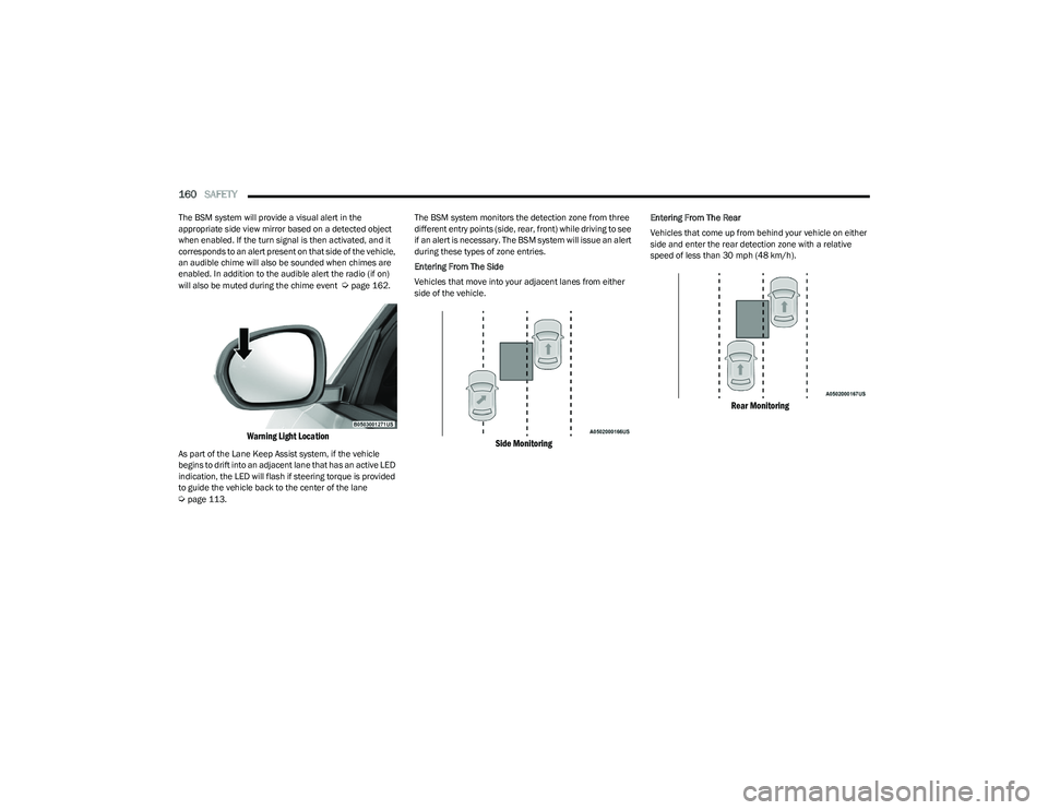
The BSM system will provide a visual alert in the
appropriate side view mirror based on a detected object
when enabled. If the turn signal is then activated, and it
corresponds to an alert present on that side of the vehicle,
an audible chime will also be sounded when chimes are
enabled. In addition to the audible alert the radio (if on)
will also be muted during the chime event
Úpage 162.
Warning Light Location
As part of the Lane Keep Assist system, if the vehicle
begins to drift into an adjacent lane that has an active LED
indication, the LED will flash if steering torque is provided
to guide the vehicle back to the center of the lane
Úpage 113. The BSM system monitors the detection zone from three
different entry points (side, rear, front) while driving to see
if an alert is necessary. The BSM system will issue an alert
during these types of zone entries.
Entering From The Side
Vehicles that move into your adjacent lanes from either
side of the vehicle.
Side Monitoring
Entering From The Rear
Vehicles that come up from behind your vehicle on either
side and enter the rear detection zone with a relative
speed of less than 30 mph (48 km/h).
Rear Monitoring
23_GG_OM_EN_USC_t.book Page 160
Page 164 of 288
162SAFETY
NOTE:In a parking lot situation, oncoming vehicles can be
blocked by vehicles parked on either side. If the sensors
are blocked by other structures or vehicles, the system will
not be able to alert the driver.
Blind Spot Modes
Blind Spot Alert has three selectable modes of operation
that are available in the Uconnect system.
Blind Spot Alert Lights Only (Default Setting)
When operating in Lights Only mode, the BSM system will
provide a visual alert in the appropriate side view mirror
based on a detected object. However, when the system is
operating in Rear Cross Path (RCP) mode, the system will
respond with both visual and audible alerts when a
detected object is present. Whenever an audible alert is
requested, the radio is muted for the duration of the
chime. Blind Spot Alert Lights/Chime
When operating in Blind Spot Alert Lights/Chime mode,
the BSM system will provide a visual alert in the
appropriate side view mirror based on a detected object.
If the turn signal is then activated, and it corresponds to
an alert present on that side of the vehicle, an audible
chime will also be sounded. Whenever a turn signal and
detected object are present on the same side at the same
time, both the visual and audible alerts will be issued. In
addition to the audible alert the radio (if on) will also be
muted.
When the system is in RCP, the system shall respond with
both visual and audible alerts when a detected object is
present. Whenever an audible alert is requested, the radio
volume is reduced. Turn/hazard signal status is ignored;
the RCP state always requests the chime.
Blind Spot Alert Off
When the BSM system is turned off, there will be no visual
or audible alerts from either the BSM or RCP systems.NOTE:The BSM system will store the current operating mode
when the vehicle is shut off. Each time the vehicle is
started the previously stored mode will be recalled and
used.
Blocked Sensor
If the system detects degraded performance due to
contamination or foreign objects, a message will warn you
of a blocked sensor and the warning indicators in side
view mirrors will be illuminated. The warning indicators will
remain illuminated until blockage clearing conditions are
met. First clear the fascia/bumper area around the sensors of the blockage. After removing the blockage,
reset the system by cycling the ignition from ON to OFF and
then back ON.
FORWARD COLLISION WARNING (FCW)
W
ITH MITIGATION — IF EQUIPPED
FCW with Mitigation provides the driver with audible
warnings, visual warnings (within the instrument cluster
display), and may apply a brake jerk to warn the driver
when it detects a potential frontal collision. The warnings
and limited braking are intended to provide the driver with
enough time to react, avoid or mitigate the potential
collision.
NOTE:FCW monitors the information from the forward looking
sensors/cameras as well as the Electronic Brake
Controller (EBC), to calculate the probability of a forward
collision. When the system determines that a forward
collision is probable, the driver will be provided with
audible and visual warnings and may provide a brake jerk
warning.
If the driver does not take action based upon these
progressive warnings, then the system will provide a
limited level of active braking to help slow the vehicle and
mitigate the potential forward collision. If the driver reacts
to the warnings by braking and the system determines
that the driver intends to avoid the collision by braking but
has not applied sufficient brake force, the system will
compensate and provide additional brake force as
required.
WARNING!
Rear Cross Path Detection (RCP) is not a backup aid
system. It is intended to be used to help a driver detect
an oncoming vehicle in a parking lot situation. Drivers
must be careful when backing up, even when using
RCP. Always check carefully behind your vehicle, look
behind you, and be sure to check for pedestrians,
animals, other vehicles, obstructions, and blind spots
before backing up. Failure to do so can result in serious
injury or death.
23_GG_OM_EN_USC_t.book Page 162
Page 165 of 288
SAFETY163
If a Forward Collision Warning with Mitigation event begins
at a speed below 39 mph (62 km/h), the system may
provide the maximum braking possible to mitigate the
potential forward collision. If the Forward Collision
Warning with Mitigation event stops the vehicle
completely, the system will hold the vehicle at standstill for
two seconds and then release the brakes.
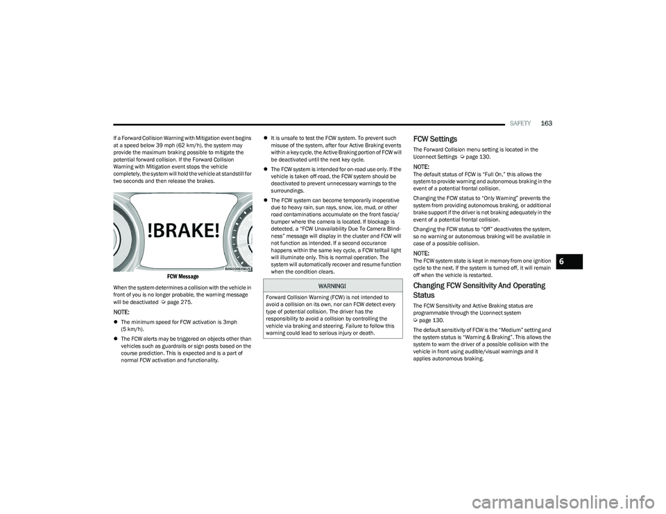
FCW Message
When the system determines a collision with the vehicle in
front of you is no longer probable, the warning message
will be deactivated
Úpage 275.
NOTE:
The minimum speed for FCW activation is 3mph
(5 km/h).
The FCW alerts may be triggered on objects other than
vehicles such as guardrails or sign posts based on the
course prediction. This is expected and is a part of
normal FCW activation and functionality.
It is unsafe to test the FCW system. To prevent such
misuse of the system, after four Active Braking events
within a key cycle, the Active Braking portion of FCW will
be deactivated until the next key cycle.
The FCW system is intended for on-road use only. If the
vehicle is taken off-road, the FCW system should be
deactivated to prevent unnecessary warnings to the
surroundings.
The FCW system can become temporarily inoperative
due to heavy rain, sun rays, snow, ice, mud, or other
road contaminations accumulate on the front fascia/
bumper where the camera is located. If blockage is
detected, a “FCW Unavailability Due To Camera Blind -
ness” message will display in the cluster and FCW will
not function as intended. If a second occurance
happens within the same key cycle, a FCW telltail light
will illuminate only. This is normal operation. The
system will automatically recover and resume function
when the condition clears.
FCW Settings
The Forward Collision menu setting is located in the
Uconnect Settings Úpage 130.
NOTE:The default status of FCW is “Full On,” this allows the
system to provide warning and autonomous braking in the
event of a potential frontal collision.
Changing the FCW status to “Only Warning” prevents the
system from providing autonomous braking, or additional
brake support if the driver is not braking adequately in the
event of a potential frontal collision.
Changing the FCW status to “Off” deactivates the system,
so no warning or autonomous braking will be available in
case of a possible collision.
NOTE:The FCW system state is kept in memory from one ignition
cycle to the next. If the system is turned off, it will remain
off when the vehicle is restarted.
Changing FCW Sensitivity And Operating
Status
The FCW Sensitivity and Active Braking status are
programmable through the Uconnect system
Úpage 130.
The default sensitivity of FCW is the “Medium” setting and
the system status is “Warning & Braking”. This allows the
system to warn the driver of a possible collision with the
vehicle in front using audible/visual warnings and it
applies autonomous braking.
WARNING!
Forward Collision Warning (FCW) is not intended to
avoid a collision on its own, nor can FCW detect every
type of potential collision. The driver has the
responsibility to avoid a collision by controlling the
vehicle via braking and steering. Failure to follow this
warning could lead to serious injury or death.
6
23_GG_OM_EN_USC_t.book Page 163
Page 166 of 288
164SAFETY
By changing the FCW status setting to "Far", the system
provides possible collision warnings on objects farther
away. This results in earlier warnings and provides the
most reaction time to avoid possible collisions.
NOTE:The “Far” setting may result in a greater number of FCW
possible collision warnings experienced.
By changing the FCW status setting to "Near", the system
provides possible collision warnings on objects closer to
the vehicle. This results in later warnings and provides
less reaction time than the "Far" and "Medium" settings,
which allows for a more dynamic driving experience.
NOTE:The “Near” setting may result in a lesser number of FCW
possible collision warnings experienced.
NOTE:
Changing the FCW status to “Only Warning” prevents
the system from providing limited active braking, or
additional brake support if the driver is not braking
adequately in the event of a potential frontal collision,
but maintains the audible and visual warnings.
Changing the FCW status to “Off” prevents the system
from providing autonomous braking, or additional
brake support if the driver is not braking adequately in
the event of a potential frontal collision.
The system will retain the last setting selected by the
driver after ignition shut down.
FCW may not react to irrelevant objects such as over -
head objects, ground reflections, objects not in the
path of the vehicle, stationary objects that are far away,
oncoming traffic, or leading vehicles with the same or
higher rates of speed.
FCW will be disabled like ACC, with the unavailable
screens.
FCW Limited Warning
If the instrument cluster display reads “FCW Limited
Functionality” or “FCW Limited Functionality Clean Front
Windshield” momentarily, there may be a condition that
limits FCW functionality. Although the vehicle is still
driveable under normal conditions, the active braking may
not be fully available. Once the condition that limited the
system performance is no longer present, the system will
return to its full performance state. If the problem persists,
see an authorized dealer.
Service FCW Warning
If the system turns off, and the instrument cluster display
reads “FCW Unavailable Service Required”, there is an
internal system fault. Although the vehicle is still driveable
under normal conditions, have the system checked by an
authorized dealer.
Pedestrian Emergency Braking (PEB) —
If Equipped
PEB is a subsystem of the Forward Collision Warning (FCW)
system which provides the driver with audible warnings
and visual warnings, in the instrument cluster display. It
may apply limited automatic braking when it detects a
potential frontal collision with a pedestrian/cyclist.
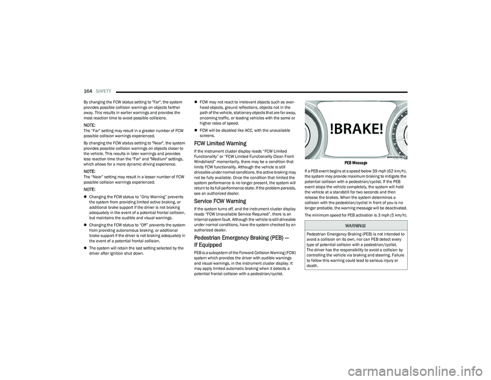
PEB Message
If a PEB event begins at a speed below 39 mph (62 km/h),
the system may provide maximum braking to mitigate the
potential collision with a pedestrian/cyclist. If the PEB
event stops the vehicle completely, the system will hold
the vehicle at a standstill for two seconds and then
release the brakes. When the system determines a
collision with the pedestrian/cyclist in front of you is no
longer probable, the warning message will be deactivated.
The minimum speed for PEB activation is 3 mph (5 km/h).
WARNING!
Pedestrian Emergency Braking (PEB) is not intended to
avoid a collision on its own, nor can PEB detect every
type of potential collision with a pedestrian/cyclist.
The driver has the responsibility to avoid a collision by
controlling the vehicle via braking and steering. Failure
to follow this warning could lead to serious injury or
death.
23_GG_OM_EN_USC_t.book Page 164
Page 168 of 288
166SAFETY
NOTE:
The TPMS is not intended to replace normal tire care
and maintenance, or to provide warning of a tire failure
or condition.
The TPMS should not be used as a tire pressure gauge
while adjusting your tire pressure.
Driving on a significantly underinflated tire causes the
tire to overheat and can lead to tire failure. Underinfla -
tion also reduces fuel efficiency and tire tread life, and
may affect the vehicle’s handling and stopping ability.
The TPMS is not a substitute for proper tire mainte -
nance, and it is the driver’s responsibility to maintain
correct tire pressure using an accurate tire pressure
gauge, even if underinflation has not reached the level
to trigger illumination of the Tire Pressure Monitoring
System Warning Light.
Seasonal temperature changes will affect tire pres -
sure, and the TPMS will monitor the actual tire pres -
sure in the tire.
Premium System
The Tire Pressure Monitoring System (TPMS) uses wireless
technology with wheel rim mounted electronic sensors to
monitor tire pressure levels. Sensors, mounted to each
wheel as part of the valve stem, transmit tire pressure
readings to the receiver module.
NOTE:It is particularly important for you to check the tire
pressure in all of the tires on your vehicle monthly and to
maintain the proper pressure.
The TPMS consists of the following components:
Receiver module
Four Tire Pressure Monitoring System sensors
Various Tire Pressure Monitoring System messages,
which will display in the instrument cluster display
Tire Pressure Monitoring System Warning Light
Tire Pressure Monitoring System Low
Pressure Warnings
The Tire Pressure Monitoring System Warning
Light will illuminate in the instrument cluster
and a chime will sound when tire pressure is
low in one or more of the four active road tires.
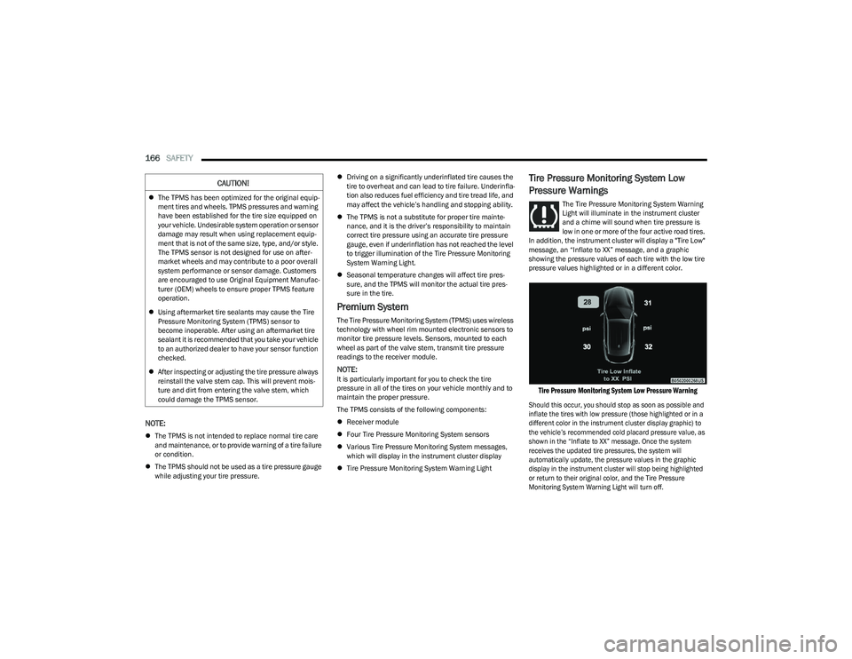
In addition, the instrument cluster will display a "Tire Low"
message, an “Inflate to XX” message, and a graphic
showing the pressure values of each tire with the low tire
pressure values highlighted or in a different color.
Tire Pressure Monitoring System Low Pressure Warning
Should this occur, you should stop as soon as possible and
inflate the tires with low pressure (those highlighted or in a
different color in the instrument cluster display graphic) to
the vehicle’s recommended cold placard pressure value, as
shown in the “Inflate to XX” message. Once the system
receives the updated tire pressures, the system will
automatically update, the pressure values in the graphic
display in the instrument cluster will stop being highlighted
or return to their original color, and the Tire Pressure
Monitoring System Warning Light will turn off.
CAUTION!
The TPMS has been optimized for the original equip -
ment tires and wheels. TPMS pressures and warning
have been established for the tire size equipped on
your vehicle. Undesirable system operation or sensor
damage may result when using replacement equip -
ment that is not of the same size, type, and/or style.
The TPMS sensor is not designed for use on after -
market wheels and may contribute to a poor overall
system performance or sensor damage. Customers
are encouraged to use Original Equipment Manufac -
turer (OEM) wheels to ensure proper TPMS feature
operation.
Using aftermarket tire sealants may cause the Tire
Pressure Monitoring System (TPMS) sensor to
become inoperable. After using an aftermarket tire
sealant it is recommended that you take your vehicle
to an authorized dealer to have your sensor function
checked.
After inspecting or adjusting the tire pressure always
reinstall the valve stem cap. This will prevent mois -
ture and dirt from entering the valve stem, which
could damage the TPMS sensor.
23_GG_OM_EN_USC_t.book Page 166
Page 184 of 288
182SAFETY
When the SAB deploys, it opens the seam on the outboard
side of the seatback’s trim cover. The inflating SAB
deploys through the seat seam into the space between the
occupant and the door. The SAB moves at a very high
speed and with such a high force that it could injure
occupants if they are not seated properly, or if items are
positioned in the area where the SAB inflates. Children are
at an even greater risk of injury from a deploying air bag.
Supplemental Side Air Bag Inflatable Curtains (SABICs)
This vehicle is equipped with Supplemental Side Air Bag
Inflatable Curtains (SABICs).
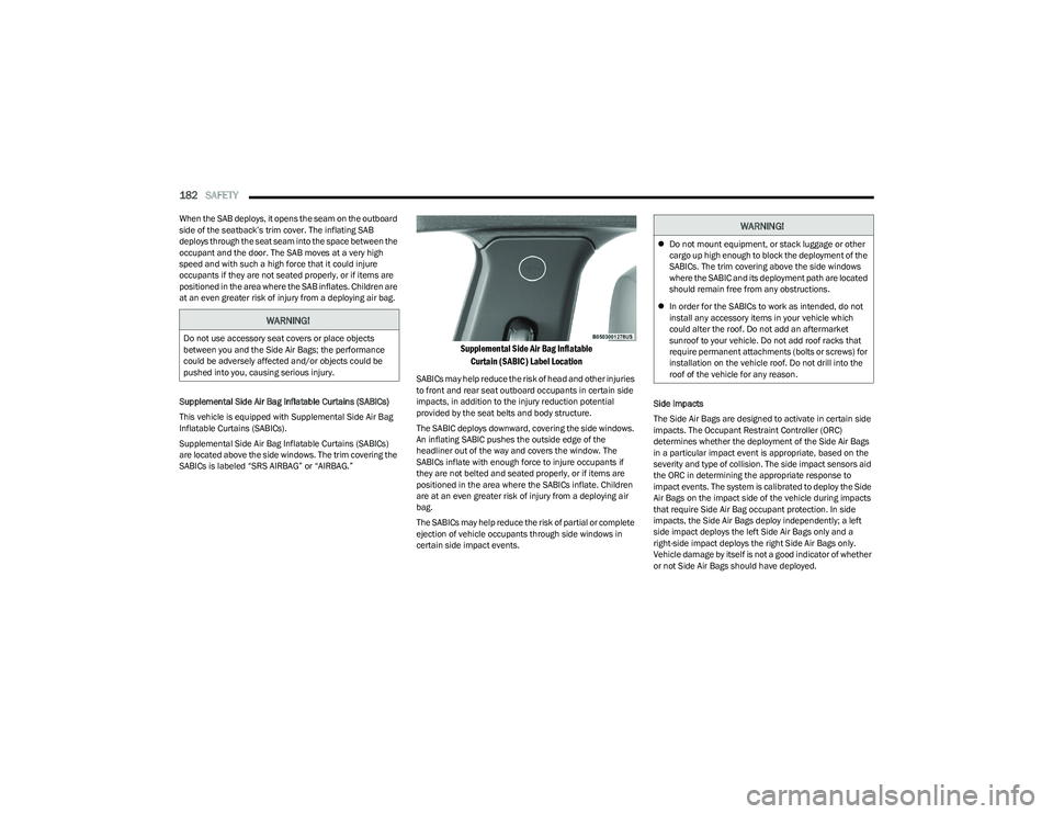
Supplemental Side Air Bag Inflatable Curtains (SABICs)
are located above the side windows. The trim covering the
SABICs is labeled “SRS AIRBAG” or “AIRBAG.”
Supplemental Side Air Bag Inflatable
Curtain (SABIC) Label Location
SABICs may help reduce the risk of head and other injuries
to front and rear seat outboard occupants in certain side
impacts, in addition to the injury reduction potential
provided by the seat belts and body structure.
The SABIC deploys downward, covering the side windows.
An inflating SABIC pushes the outside edge of the
headliner out of the way and covers the window. The
SABICs inflate with enough force to injure occupants if
they are not belted and seated properly, or if items are
positioned in the area where the SABICs inflate. Children
are at an even greater risk of injury from a deploying air
bag.
The SABICs may help reduce the risk of partial or complete
ejection of vehicle occupants through side windows in
certain side impact events. Side Impacts
The Side Air Bags are designed to activate in certain side
impacts. The Occupant Restraint Controller (ORC)
determines whether the deployment of the Side Air Bags
in a particular impact event is appropriate, based on the
severity and type of collision. The side impact sensors aid
the ORC in determining the appropriate response to
impact events. The system is calibrated to deploy the Side
Air Bags on the impact side of the vehicle during impacts
that require Side Air Bag occupant protection. In side
impacts, the Side Air Bags deploy independently; a left
side impact deploys the left Side Air Bags only and a
right-side impact deploys the right Side Air Bags only.
Vehicle damage by itself is not a good indicator of whether
or not Side Air Bags should have deployed.
WARNING!
Do not use accessory seat covers or place objects
between you and the Side Air Bags; the performance
could be adversely affected and/or objects could be
pushed into you, causing serious injury.
WARNING!
Do not mount equipment, or stack luggage or other
cargo up high enough to block the deployment of the
SABICs. The trim covering above the side windows
where the SABIC and its deployment path are located
should remain free from any obstructions.
In order for the SABICs to work as intended, do not
install any accessory items in your vehicle which
could alter the roof. Do not add an aftermarket
sunroof to your vehicle. Do not add roof racks that
require permanent attachments (bolts or screws) for
installation on the vehicle roof. Do not drill into the
roof of the vehicle for any reason.
23_GG_OM_EN_USC_t.book Page 182
Page 186 of 288
184SAFETY
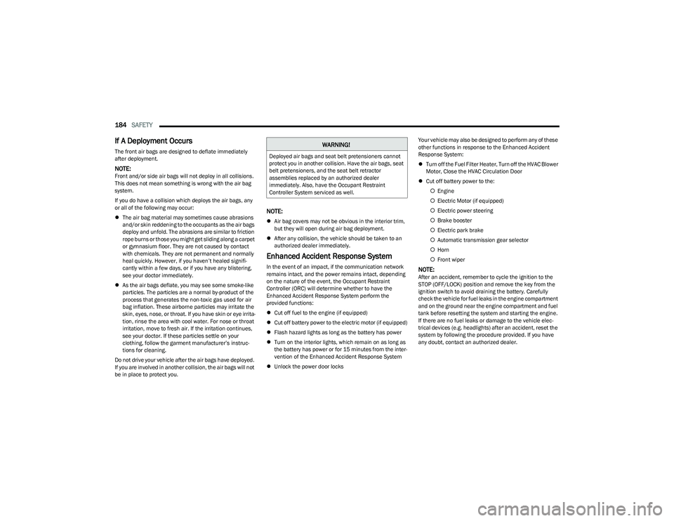
If A Deployment Occurs
The front air bags are designed to deflate immediately
after deployment.
NOTE:Front and/or side air bags will not deploy in all collisions.
This does not mean something is wrong with the air bag
system.
If you do have a collision which deploys the air bags, any
or all of the following may occur:
The air bag material may sometimes cause abrasions
and/or skin reddening to the occupants as the air bags
deploy and unfold. The abrasions are similar to friction
rope burns or those you might get sliding along a carpet
or gymnasium floor. They are not caused by contact
with chemicals. They are not permanent and normally
heal quickly. However, if you haven’t healed signifi -
cantly within a few days, or if you have any blistering,
see your doctor immediately.
As the air bags deflate, you may see some smoke-like
particles. The particles are a normal by-product of the
process that generates the non-toxic gas used for air
bag inflation. These airborne particles may irritate the
skin, eyes, nose, or throat. If you have skin or eye irrita -
tion, rinse the area with cool water. For nose or throat
irritation, move to fresh air. If the irritation continues,
see your doctor. If these particles settle on your
clothing, follow the garment manufacturer’s instruc -
tions for cleaning.
Do not drive your vehicle after the air bags have deployed.
If you are involved in another collision, the air bags will not
be in place to protect you.
NOTE:
Air bag covers may not be obvious in the interior trim,
but they will open during air bag deployment.
After any collision, the vehicle should be taken to an
authorized dealer immediately.
Enhanced Accident Response System
In the event of an impact, if the communication network
remains intact, and the power remains intact, depending
on the nature of the event, the Occupant Restraint
Controller (ORC) will determine whether to have the
Enhanced Accident Response System perform the
provided functions:
Cut off fuel to the engine (if equipped)
Cut off battery power to the electric motor (if equipped)
Flash hazard lights as long as the battery has power
Turn on the interior lights, which remain on as long as
the battery has power or for 15 minutes from the inter -
vention of the Enhanced Accident Response System
Unlock the power door locks Your vehicle may also be designed to perform any of these
other functions in response to the Enhanced Accident
Response System:
Turn off the Fuel Filter Heater, Turn off the HVAC Blower
Motor, Close the HVAC Circulation Door
Cut off battery power to the:
Engine
Electric Motor (if equipped)
Electric power steering
Brake booster
Electric park brake
Automatic transmission gear selector
Horn
Front wiperNOTE:After an accident, remember to cycle the ignition to the
STOP (OFF/LOCK) position and remove the key from the
ignition switch to avoid draining the battery. Carefully
check the vehicle for fuel leaks in the engine compartment
and on the ground near the engine compartment and fuel
tank before resetting the system and starting the engine.
If there are no fuel leaks or damage to the vehicle elec -
trical devices (e.g. headlights) after an accident, reset the
system by following the procedure provided. If you have
any doubt, contact an authorized dealer.
WARNING!
Deployed air bags and seat belt pretensioners cannot
protect you in another collision. Have the air bags, seat
belt pretensioners, and the seat belt retractor
assemblies replaced by an authorized dealer
immediately. Also, have the Occupant Restraint
Controller System serviced as well.
23_GG_OM_EN_USC_t.book Page 184
Page 187 of 288
SAFETY185
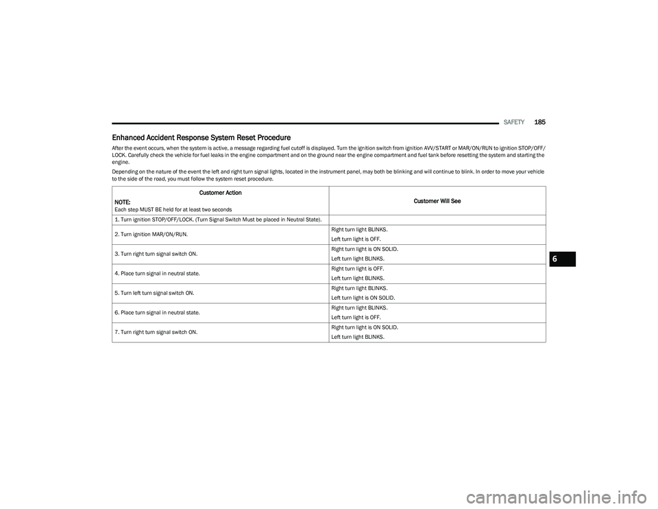
Enhanced Accident Response System Reset Procedure
After the event occurs, when the system is active, a message regarding fuel cutoff is displayed. Turn the ignition switch from ignition AVV/START or MAR/ON/RUN to ignition STOP/OFF/
LOCK. Carefully check the vehicle for fuel leaks in the engine compartment and on the ground near the engine compartment and fuel tank before resetting the system and starting the
engine.
Depending on the nature of the event the left and right turn signal lights, located in the instrument panel, may both be blinking and will continue to blink. In order to move your vehicle
to the side of the road, you must follow the system reset procedure.
Customer Action
NOTE:
Each step MUST BE held for at least two seconds
Customer Will See
1. Turn ignition STOP/OFF/LOCK. (Turn Signal Switch Must be placed in Neutral State).
2. Turn ignition MAR/ON/RUN. Right turn light BLINKS.
Left turn light is OFF.
3. Turn right turn signal switch ON. Right turn light is ON SOLID.
Left turn light BLINKS.
4. Place turn signal in neutral state. Right turn light is OFF.
Left turn light BLINKS.
5. Turn left turn signal switch ON. Right turn light BLINKS.
Left turn light is ON SOLID.
6. Place turn signal in neutral state. Right turn light BLINKS.
Left turn light is OFF.
7. Turn right turn signal switch ON. Right turn light is ON SOLID.
Left turn light BLINKS.
6
23_GG_OM_EN_USC_t.book Page 185