reset DODGE HORNET 2023 Owners Manual
[x] Cancel search | Manufacturer: DODGE, Model Year: 2023, Model line: HORNET, Model: DODGE HORNET 2023Pages: 288, PDF Size: 14.2 MB
Page 5 of 288
3
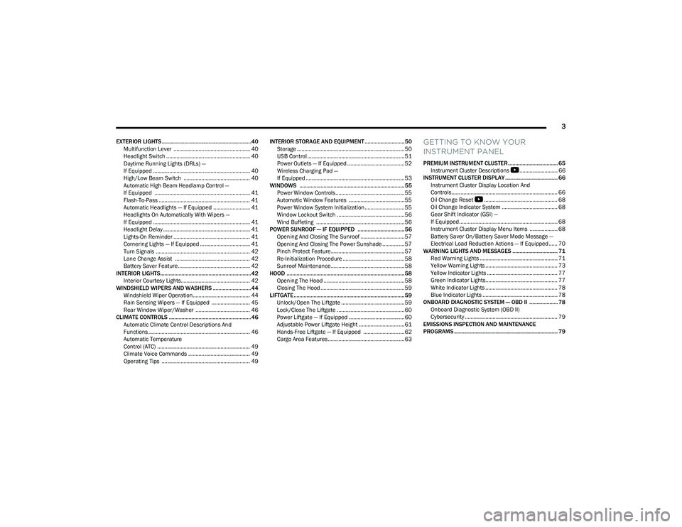
EXTERIOR LIGHTS ...............................................................40Multifunction Lever .................................................... 40
Headlight Switch ......................................................... 40
Daytime Running Lights (DRLs) —
If Equipped .................................................................. 40
High/Low Beam Switch ............................................. 40
Automatic High Beam Headlamp Control —
If Equipped ................................................................. 41
Flash-To-Pass .............................................................. 41
Automatic Headlights — If Equipped ......................... 41
Headlights On Automatically With Wipers —
If Equipped .................................................................. 41
Headlight Delay ........................................................... 41
Lights-On Reminder .................................................... 41
Cornering Lights — If Equipped .................................. 41
Turn Signals ................................................................ 42
Lane Change Assist ................................................... 42
Battery Saver Feature................................................. 42
INTERIOR LIGHTS................................................................42 Interior Courtesy Lights............................................... 42
WINDSHIELD WIPERS AND WASHERS ........................... 44 Windshield Wiper Operation....................................... 44
Rain Sensing Wipers — If Equipped .......................... 45
Rear Window Wiper/Washer ..................................... 46
CLIMATE CONTROLS ..........................................................46 Automatic Climate Control Descriptions And
Functions ..................................................................... 46
Automatic Temperature
Control (ATC) ............................................................... 49
Climate Voice Commands .......................................... 49
Operating Tips ............................................................ 49 INTERIOR STORAGE AND EQUIPMENT ............................ 50
Storage ......................................................................... 50
USB Control .................................................................. 51
Power Outlets — If Equipped ....................................... 52
Wireless Charging Pad —
If Equipped ................................................................... 53
WINDOWS .......................................................................... 55 Power Window Controls............................................... 55
Automatic Window Features ......................................55
Power Window System Initialization........................... 55
Window Lockout Switch ..............................................56
Wind Buffeting ............................................................ 56
POWER SUNROOF — IF EQUIPPED ................................. 56 Opening And Closing The Sunroof ..............................57
Opening And Closing The Power Sunshade ............... 57
Pinch Protect Feature.................................................. 57
Re-Initialization Procedure .......................................... 58
Sunroof Maintenance.................................................. 58
HOOD ................................................................................... 58 Opening The Hood .......................................................58
Closing The Hood ......................................................... 59
LIFTGATE .............................................................................. 59 Unlock/Open The Liftgate ........................................... 59
Lock/Close The Liftgate ..............................................60
Power Liftgate — If Equipped ......................................60
Adjustable Power Liftgate Height ............................... 61
Hands-Free Liftgate — If Equipped ............................ 62
Cargo Area Features.................................................... 63GETTING TO KNOW YOUR
INSTRUMENT PANEL
PREMIUM INSTRUMENT CLUSTER................................... 65 Instrument Cluster Descriptions
b
.......................... 66
INSTRUMENT CLUSTER DISPLAY ..................................... 66 Instrument Cluster Display Location And
Controls........................................................................ 66
Oil Change Reset
b
.................................................. 68
Oil Change Indicator System ...................................... 68
Gear Shift Indicator (GSI) —
If Equipped................................................................... 68
Instrument Cluster Display Menu Items ................... 68
Battery Saver On/Battery Saver Mode Message —
Electrical Load Reduction Actions — If Equipped ...... 70
WARNING LIGHTS AND MESSAGES ................................ 71 Red Warning Lights ..................................................... 71
Yellow Warning Lights ................................................. 73
Yellow Indicator Lights ................................................ 77
Green Indicator Lights................................................. 77
White Indicator Lights ................................................. 78
Blue Indicator Lights ................................................... 78
ONBOARD DIAGNOSTIC SYSTEM — OBD II .................... 78 Onboard Diagnostic System (OBD II)
Cybersecurity ............................................................... 79
EMISSIONS INSPECTION AND MAINTENANCE
PROGRAMS ......................................................................... 79
23_GG_OM_EN_USC_t.book Page 3
Page 22 of 288
20GETTING TO KNOW YOUR VEHICLE
REMOTE START ABORT MESSAGE —
I
F EQUIPPED
One of the following messages will display in the
instrument cluster display if the vehicle fails to remote
start or exits Remote Start prematurely:
Remote Start Aborted — Door Open
Remote Start Aborted — Hood Open
Remote Start Aborted — Fuel Low
Remote Start Aborted — Liftgate Open
Remote Start Aborted — Too Cold
Remote Start Aborted — Time Expired
Remote Start Disabled — Start Vehicle To Reset
The message will stay active until the ignition is placed in
the ON/RUN position.
VEHICLE SECURITY SYSTEM — IF EQUIPPED
The Vehicle Security system monitors the vehicle doors,
hood, liftgate, and the Keyless Enter ‘n Go™ Ignition for
unauthorized operation. It also monitors movement inside
the passenger compartment (volumetric protection —
if equipped), cutting of battery cables, and unexpected
lifting/tilting of the vehicle (anti-lift protection —
if equipped). If something triggers the system, the Vehicle Security
system will provide the following audible and visible
signals:
The horn will pulse
The turn signals will flash
NOTE:
The Vehicle Security system is activated by the Engine
Immobilizer system, which is automatically activated
when you get out of the vehicle with the key fob and
lock the doors.
The Vehicle Security system is factory adjusted to stan -
dards from different countries.
The Vehicle Security system is a complementary secu -
rity system developed to hinder the occurrence of
vehicle theft and prevent vandalism. It does not
prevent the theft of your vehicle; the system is a deter -
rent.
TO ARM THE SYSTEM
Follow these steps to arm the Vehicle Security system:
1. Make sure the vehicle’s ignition is placed in the OFF position.
For vehicles equipped with Keyless Entry, make
sure the vehicle’s keyless ignition system is OFF. 2. Perform one of the following methods to lock the
vehicle:
Push the lock button on the interior power door
lock switch with the driver and/or passenger door
open.
Push the lock button on the exterior Passive Entry
door handle with a valid key fob available in the
same exterior zone
Úpage 23.
Push the lock button on the key fob.
3. If any doors (or liftgate) are open, close them.
When the Vehicle Security system is armed (except on
some versions for specific markets), the system will emit
an acoustic warning and a warning light (located next to
the interior door handle) will flash until it is disarmed.
NOTE:
If there is a fault with the system, the system will emit
an acoustic signal a second time.
If this occurs, wait about 4 seconds and switch off the
Vehicle Security system following this procedure:
a. Press the unlock button on the key fob.
b. Check that the doors, hood, and liftgate are closed, and then reactivate the system by pressing
the lock button.
If the alarm emits a sound even when the doors, hood,
and liftgate are closed, there is a fault with the system.
Contact an authorized dealer for assistance.
The vehicle doors can be locked without arming the
Vehicle Security system by using the emergency key in
the exterior door lock cylinder.
23_GG_OM_EN_USC_t.book Page 20
Page 29 of 288
GETTING TO KNOW YOUR VEHICLE27
For information on use with the Remote Start system, see Úpage 19.
DRIVER MEMORY SETTINGS — IF EQUIPPED
This feature allows the driver to save up to two different
memory profiles for easy recall through a memory switch.
Each memory profile saves desired position settings for
the following features:
Driver seat position
A set of desired radio station presets
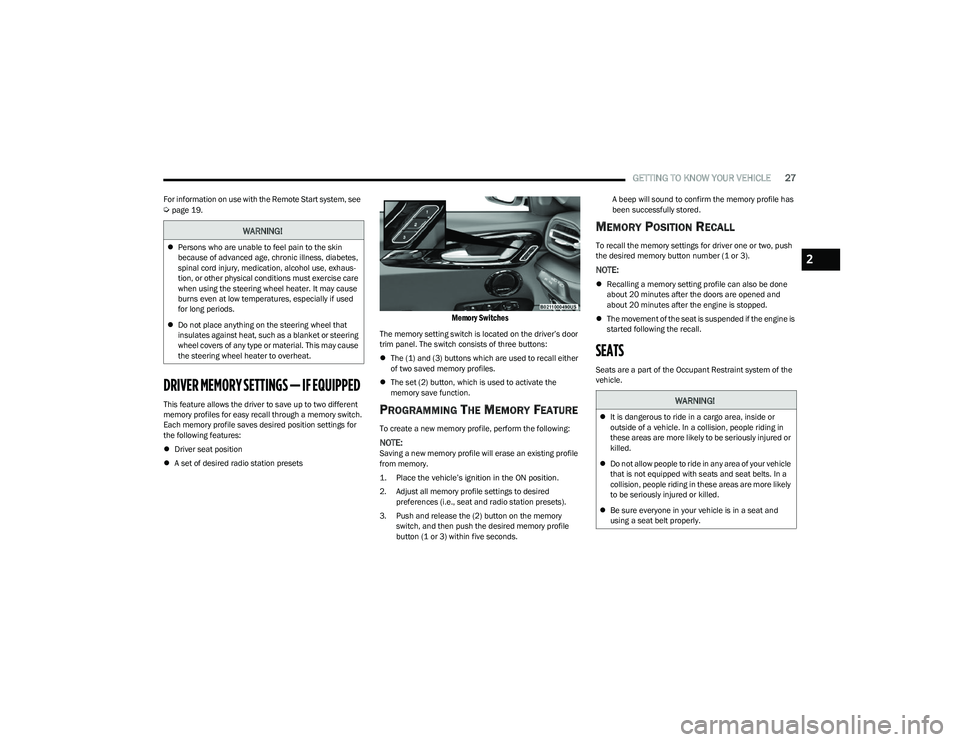
Memory Switches
The memory setting switch is located on the driver’s door
trim panel. The switch consists of three buttons:
The (1) and (3) buttons which are used to recall either
of two saved memory profiles.
The set (2) button, which is used to activate the
memory save function.
PROGRAMMING THE MEMORY FEATURE
To create a new memory profile, perform the following:
NOTE:Saving a new memory profile will erase an existing profile
from memory.
1. Place the vehicle’s ignition in the ON position.
2. Adjust all memory profile settings to desired
preferences (i.e., seat and radio station presets).
3. Push and release the (2) button on the memory switch, and then push the desired memory profile
button (1 or 3) within five seconds. A beep will sound to confirm the memory profile has
been successfully stored.
MEMORY POSITION RECALL
To recall the memory settings for driver one or two, push
the desired memory button number (1 or 3).
NOTE:
Recalling a memory setting profile can also be done
about 20 minutes after the doors are opened and
about 20 minutes after the engine is stopped.
The movement of the seat is suspended if the engine is
started following the recall.
SEATS
Seats are a part of the Occupant Restraint system of the
vehicle.
WARNING!
Persons who are unable to feel pain to the skin
because of advanced age, chronic illness, diabetes,
spinal cord injury, medication, alcohol use, exhaus -
tion, or other physical conditions must exercise care
when using the steering wheel heater. It may cause
burns even at low temperatures, especially if used
for long periods.
Do not place anything on the steering wheel that
insulates against heat, such as a blanket or steering
wheel covers of any type or material. This may cause
the steering wheel heater to overheat.
WARNING!
It is dangerous to ride in a cargo area, inside or
outside of a vehicle. In a collision, people riding in
these areas are more likely to be seriously injured or
killed.
Do not allow people to ride in any area of your vehicle
that is not equipped with seats and seat belts. In a
collision, people riding in these areas are more likely
to be seriously injured or killed.
Be sure everyone in your vehicle is in a seat and
using a seat belt properly.
2
23_GG_OM_EN_USC_t.book Page 27
Page 63 of 288
GETTING TO KNOW YOUR VEHICLE61
NOTE:
Before closing the liftgate, make sure to be in posses -
sion of the key fob because the liftgate may be locked.
Use the interior door lock/unlock button on the door
panel or the key fob to lock and unlock the liftgate. The
manual door locks on the doors and the exterior door
lock cylinder will not lock and unlock the liftgate.
The liftgate will either unlock along with the vehicle
doors, or it will need to be unlocked by pushing the
electronic liftgate release, depending on the selected
setting in the Uconnect system
Úpage 130.
The power liftgate buttons will not operate if the vehicle
is in gear or the vehicle speed is above 0 mph (0 km/h).
The power liftgate will not operate in temperatures
below −22°F (−30°C) or temperatures above 150°F
(65°C). Be sure to remove any buildup of snow or ice
from the liftgate before pushing any of the power lift -
gate switches.
If anything obstructs the power liftgate while it is
closing or opening, the liftgate will automatically
reverse to the closed or open position. After multiple
obstructions in the same cycle, the liftgate will auto -
matically stop and must be opened or closed manually.
There are pinch sensors attached to the side of the lift -
gate. Light pressure anywhere along these strips will
cause the liftgate to return to the open position.
The power liftgate must be in the full open position in
order for the rear liftgate close button, on the located
on the base of the liftgate, to operate. If the liftgate is
not fully open, push the liftgate button on the key fob to
fully open the liftgate and then push it again to close.
If the electronic liftgate release handle is pushed a
second time while the power liftgate is opening, the
liftgate motor will disengage to allow manual operation.
If your liftgate is power closing and you put the vehicle
in gear, the liftgate will continue to power close.
However, vehicle movement may result in the detec -
tion of an obstruction.
Allow the power system to open the liftgate. Manually
pushing or pulling the liftgate may activate the liftgate
obstacle detection feature and stop the power opera -
tion or reverse its direction.
ADJUSTABLE POWER LIFTGATE HEIGHT
The maximum height that the liftgate will open can be
adjusted and saved so that the liftgate will only open to the
desired height. To set a desired height, proceed as follows:
1. Open the liftgate fully, then manually pull down on the liftgate to the desired height.
2. Push and hold the liftgate close button or the lock button, which are both located on the bottom of
the liftgate, for three seconds. The turn signals will
flash three times to indicate successful activation.
The liftgate is now programmed to open to the set
position.
To set the saved height setting to one of four preset
positions, select the desired setting in Uconnect Settings
Úpage 130.
Power Liftgate Malfunction Procedure:
1. In the event of a power malfunction to the liftgate, the liftgate can be released by accessing the service
release feature in the latch. This can be done using
a 3 mm diameter screwdriver.
2. From inside the gate, an eyelet can be seen. Place the screwdriver in the eyelet.
3. Rotate the screwdriver handle to actuate the lever and release the latch.
4. If liftgate is left open for an extended period of time, the liftgate may need to be closed manually to reset
power liftgate functionality.
WARNING!
Driving with the liftgate open can allow poisonous
exhaust gases into your vehicle. You and your
passengers could be injured by these fumes.
Keep the liftgate closed when you are operating
the vehicle.
If you are required to drive with the liftgate open,
make sure that all windows are closed, and the
climate control blower switch is set at high speed.
Do not use the recirculation mode.
During power operation, personal injury or cargo
damage may occur. Ensure the liftgate travel path is
clear. Make sure the liftgate is closed and latched
before driving away.
Personal injury or cargo damage may occur if caught
in the path of the liftgate. Make sure the liftgate path
is clear before activating the liftgate.
2
23_GG_OM_EN_USC_t.book Page 61
Page 64 of 288
62GETTING TO KNOW YOUR VEHICLE
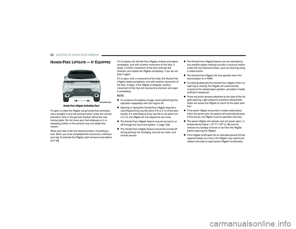
HANDS-FREE LIFTGATE — IF EQUIPPED
Hands-Free Liftgate Activation Zone
To open or close the liftgate using hands-free activation,
use a straight in and out kicking motion under the vehicle
activation zone in the general location below the rear
license plate. Do not move your foot sideways or in a
sweeping motion or the sensors may not detect the
motion.
Move your foot under the fascia/bumper, simulating a
kick. When you have completed this movement, withdraw
your leg. To activate the liftgate, both sensors must detect
your leg. If it is closed, the Hands-Free Liftgate unlocks and opens
completely, and with another movement of the foot, it
stops. A further movement of the foot reverses the
direction and closes the liftgate completely, if you do not
stop it again.
If it is open, with a movement of the foot, the Hands-Free
Liftgate closes completely, and with another movement of
the foot, it stops. If the liftgate is stopped, another
movement of the foot will reverse the direction and open
it completely.
NOTE:
To conserve the battery charge, avoid performing this
operation repeatedly with the engine off.
Opening or closing the Hands-Free Liftgate requires a
valid Passive Entry key fob within 5 ft (1.5 m) of the door
handle. If a valid Passive Entry key fob is not within 5 ft
(1.5 m), the liftgate will not respond to any kicks.
The Hands-Free Liftgate feature may be turned on or
off through the Uconnect system
Úpage 130.
The Hands-Free Liftgate feature should be turned off
during jacking, tire changing, manual car wash, and
vehicle service.
The Hands-Free Liftgate feature can be activated by
any metallic object making a similar in-and-out motion
under the rear fascia/bumper, such as cleaning using
a metal broom.
The Hands-Free Liftgate will only operate when the
transmission is in PARK.
If anything obstructs the Hands-Free Liftgate while it is
opening or closing, the liftgate will automatically
reverse to the closed/open position, provided it meets
sufficient resistance.
There are pinch sensors attached to the side of the lift -
gate opening. Light pressure anywhere along these
strips will cause the liftgate to return to the open posi -
tion.
If the power liftgate encounters multiple obstructions
within the same cycle, the system will automatically stop.
If this occurs, the liftgate must be operated manually.
The power liftgate will release, but not power open, in
temperatures below −12°F (−24°C). Be sure to
remove any buildup of snow or ice from the liftgate
before opening the liftgate.
If the liftgate is left open for an extended period of time
(approximately one hour), the liftgate may need to be
closed manually to reset power liftgate functionality.
23_GG_OM_EN_USC_t.book Page 62
Page 70 of 288
68GETTING TO KNOW YOUR INSTRUMENT PANEL
Unstored Messages
This message type is displayed indefinitely or until the
condition that activated the message is cleared. Exam -
ples of this message type are “Turn Signal On” (if a turn
signal is left on) and “Lights On” (if driver leaves the
vehicle with the lights on).
Unstored Messages Until RUN
These messages deal primarily with the Remote Start
feature. This message type is displayed until the igni -
tion is in the RUN state. Examples of this message type
are “Remote Start Canceled - Door Ajar” and
“Press Brake Pedal and Push Button to Start.”
Five Second Unstored Messages
When the appropriate conditions occur, this type of
message takes control of the main display area for
five seconds and then returns to the previous screen.
An example of this message type is “Automatic High
Beams On.”
OIL CHANGE RESET
Use this QR code to access your digital
experience.
Your vehicle is equipped with an
engine oil change indicator system.
A message will display in the instru -
ment cluster display for five
seconds to indicate the next sched -
uled oil change interval is due. The
engine oil change indicator system is duty cycle based,
which means the engine oil change interval may fluc -
tuate, dependent upon your personal driving style.
Unless reset, this message will continue to display
each time the ignition is cycled to the ON/RUN position.
To reset the oil change indicator after performing the
scheduled maintenance, refer to the following procedure:
1. Without pressing the brake pedal, push the ENGINE START/STOP button and cycle the ignition to the
ON/RUN position (do not start the engine).
2. Fully press the accelerator pedal, slowly, three times within ten seconds.
3. Cycle the ignition to the OFF position.
NOTE:If the indicator message illuminates when you start the
vehicle, the oil change indicator system did not reset. If
necessary, repeat this procedure.
OIL CHANGE INDICATOR SYSTEM
Your vehicle is equipped with an engine oil change
indicator system. The “Oil Change Due” message will
display in the instrument cluster display for five seconds
after a single chime has sounded, to indicate the next
scheduled oil change interval. The engine oil change
indicator system is duty cycle based, which means the
engine oil change interval may fluctuate, dependent upon
your personal driving style.
GEAR SHIFT INDICATOR (GSI) —
I
F EQUIPPED
The GSI system is enabled on vehicles with a manual
transmission, or when a vehicle with an automatic
transmission is in manual shift mode. The GSI provides
the driver with a visual indication when the recommended gear shift point has been reached. This indication notifies
the driver that changing gear will allow a reduction in fuel
consumption. When the up shift indicator is shown on the
instrument cluster display, the GSI is advising the driver to
engage a higher gear. When the down shift indicator is
shown on the display, the GSI is advising the driver to
engage a lower gear.
The GSI remains illuminated until the driver changes
gears, or the driving conditions return to a situation where
changing gear is not required to improve fuel
consumption.
INSTRUMENT CLUSTER DISPLAY MENU
I
TEMS
The instrument cluster display can be used to view the
main menu items for several features. Use the up and
down arrow buttons to scroll through the driver
interactive display menu options until the desired menu is
reached.
NOTE:The instrument cluster display menu items display in the
center of the instrument cluster. Menu items may vary
depending on your vehicle features.
Main Menu
Use the Thumbwheel to scroll Up and Down through the
Menu options. Press the Thumbwheel to enter and exit the
highlighted menu option.
NOTE:These Menu options may vary based on your vehicles trim
level.
23_GG_OM_EN_USC_t.book Page 68
Page 71 of 288
GETTING TO KNOW YOUR INSTRUMENT PANEL69
SPEEDOMETER
The Speedometer menu options may consist of the
following:
Digital speed and speed unit (MPH or km/h)
Gear Shift Indicator (GSI)
Gear
Drive mode name
The speed units can be changed from MPH to km/h by
pressing the Thumbwheel.
NAVIGATION — IF EQUIPPED
Turn the Thumbwheel up or down to increase or decrease
the zoom on this screen. Press the Thumbwheel to go
back to the initial frame. The zoom level is automatically
reset to the factory settings whenever the engine is
restarted.
The following information is shown:
Direction Indicators
Distance to next change of direction (in miles or kilome -
ters, depending on instrument panel settings)
Suggested lanes
Address of the road to be followed after the change of
direction Press and hold the Thumbwheel to disable the indications
in the right-hand ring for the current navigation. If a
predicted route is selected, the route shall start without
further confirmation.
NOTE:During projection modes (Apple CarPlay® or
Android Auto™) the native map is not available.
PHONE
This menu displays the current status of a phone
connected to the vehicle via Bluetooth®. The System
supports up to two phones connected at the same time.
Information available in cluster depends on which phone
is dynamically selected by the user in each moment (i.e.
the phone in focus), to enter and select one of the phone
connected user should press Thumbwheel
If no phone is connected, the menu will not function when
the
OK button is pushed. Otherwise, if a phone is
connected, push the OK button to enter the menu.
The following items will display:
Recent calls: displays a list of the last 10 calls.
SMS reader: displays the last 10 text messages and if
they are read or unread.
Favorite numbers: displays a maximum of 10 favorite
numbers.
PERFORMANCE
Performance page content automatically changes
according to the selected drive mode.
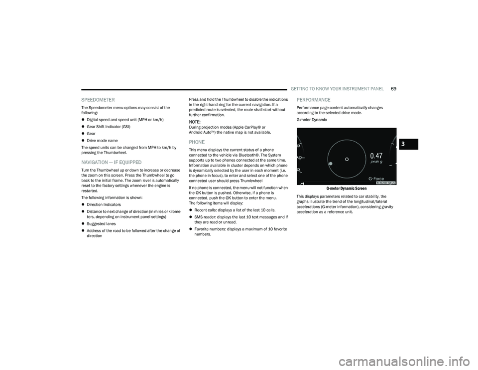
G-meter Dynamic
G-meter Dynamic Screen
This displays parameters related to car stability, the
graphs illustrate the trend of the longitudinal/lateral
accelerations (G-meter information), considering gravity
acceleration as a reference unit.
3
23_GG_OM_EN_USC_t.book Page 69
Page 87 of 288
STARTING AND OPERATING85
(Continued)
(Continued)
When Brake Service Mode work is complete, the following
steps must be followed to reset the parking brake system
to normal operation:
Ensure the vehicle is at a standstill.
Press the brake pedal with moderate force.
Apply the EPB Switch.
NOTE:A dedicated message will appear in the instrument cluster
display if Brake Service Mode cannot be deactivated.
AUTOMATIC TRANSMISSION
You must press and hold the brake pedal while shifting out
of PARK.
WARNING!
You can be badly injured working on or around a motor
vehicle. Do only that service work for which you have
the knowledge and the right equipment. If you have any
doubt about your ability to perform a service job, take
your vehicle to a competent mechanic.
WARNING!
Never use the PARK (P) position as a substitute for
the parking brake. Always apply the parking brake
fully when exiting the vehicle to guard against vehicle
movement and possible injury or damage.
Your vehicle could move and injure you and others if
it is not in PARK. Check by trying to move the gear
selector out of PARK with the brake pedal released.
Make sure the transmission is in PARK before exiting
the vehicle.
It is dangerous to shift out of PARK or NEUTRAL (N) if
the engine speed is higher than idle speed. If your
foot is not firmly pressing the brake pedal, the
vehicle could accelerate quickly forward or in
reverse. You could lose control of the vehicle and hit
someone or something. Only shift into gear when the
engine is idling normally and your foot is firmly
pressing the brake pedal.
The vehicle may not engage a newly selected gear
when shifting between PARK, REVERSE (R), or
DRIVE (D) if the vehicle is moving while shifting.
Unintended movement of a vehicle could injure
those in or near the vehicle. As with all vehicles, you
should never exit a vehicle while the engine is
running. Before exiting a vehicle, always come to a
complete stop, then apply the parking brake, shift
the transmission into PARK, and turn the ignition
OFF. When the ignition is in the OFF position, the
transmission is locked in PARK, securing the vehicle
against unwanted movement.
When leaving the vehicle, always make sure the igni -
tion is in the OFF position, remove the key fob from
the vehicle, and lock the vehicle.
WARNING!
Never leave children alone in a vehicle, or with
access to an unlocked vehicle. Allowing children to
be in a vehicle unattended is dangerous for a
number of reasons. A child or others could be seri -
ously or fatally injured. Children should be warned
not to touch the parking brake, brake pedal or the
transmission gear selector.
Do not leave the key fob in or near the vehicle (or in
a location accessible to children), and do not leave
the ignition in the ON/RUN position. A child could
operate power windows, other controls, or move the
vehicle.
CAUTION!
Damage to the transmission may occur if the following
precautions are not observed:
Shift into or out of PARK or REVERSE only after the
vehicle has come to a complete stop.
Do not shift between PARK, REVERSE, NEUTRAL, or
DRIVE when the engine is above idle speed.
Before shifting into any gear, make sure your foot is
firmly pressing the brake pedal.
WARNING!
4
23_GG_OM_EN_USC_t.book Page 85
Page 90 of 288
88STARTING AND OPERATING
In the event of a momentary problem, the transmission
can be reset to regain all forward gears by performing the
following steps:
1. Stop the vehicle.
2. Shift the transmission into PARK (P), if possible. If
not, shift the transmission to NEUTRAL.
3. Push and hold the ignition until the engine turns off.
4. Wait approximately 30 seconds.
5. Restart the engine.
6. Shift into the desired gear range. If the problem is no longer detected, the transmission will return to
normal operation.
NOTE:Even if the transmission can be reset, we recommend that
you visit an authorized dealer at your earliest possible
convenience. An authorized dealer has diagnostic
equipment to assess the condition of your transmission.
If the transmission cannot be reset, authorized dealer
service is required.
TORQUE CONVERTER CLUTCH
A feature designed to improve fuel economy has been
included in the automatic transmission on your vehicle.
A clutch within the torque converter engages
automatically at calibrated speeds. This may result in a
slightly different feeling or response during normal
operation in the upper gears. When the vehicle speed
drops or during some accelerations, the clutch
automatically disengages.
NOTE:The torque converter clutch will not engage until the
engine and/or transmission is warm (usually after 1 to
3 miles [2 to 5 km] of driving). Because the engine speed
is higher when the torque converter clutch is not engaged,
it may seem as if the transmission is not shifting properly
when the vehicle is cold. This is normal. The torque
converter clutch will function normally once the powertrain
is sufficiently warm.
ALL-WHEEL DRIVE (AWD)
This feature provides on-demand All-Wheel Drive (AWD).
The system is automatic with no driver inputs or additional
driving skills required. Under normal driving conditions,
the front wheels provide most of the traction. If the front
wheels begin to lose traction, power is shifted
automatically to the rear wheels. The greater the front
wheel traction loss, the greater the power transfer to the
rear wheels.
Additionally, on dry pavement under heavy throttle input
(where one may have no wheel spin), torque will be sent to
the rear in a preemptive effort to improve vehicle launch
and performance characteristics.
SPORT MODE — IF EQUIPPED
Your vehicle is equipped with a SPORT Mode feature. The
engine, transmission, and steering systems are all set to
their SPORT settings. SPORT Mode will provide improved
throttle response and modified transmission shift points
for an enhanced driving experience, as well as greater
amount of steering feel.
This mode may be activated and deactivated by pushing
the SPORT button on the steering wheel. For PHEV
versions the SPORT button is located below the STOP/
START button.
POWER STEERING
The electric power steering system will provide increased
vehicle response and ease of maneuverability. The electric
power steering system adapts to different driving conditions.
If the “SERVICE POWER STEERING” or “POWER
STEERING ASSIST OFF - SERVICE SYSTEM”
message and a steering wheel icon display on
the instrument cluster, it indicates that the
vehicle needs service. It may be necessary to perform the
recalibration maneuver by turning the steering wheel from
full left position to full right position. If the problem is still
present, take the vehicle to an authorized dealer for
service. It is likely the vehicle has lost power steering
assistance
Úpage 66.
CAUTION!
All wheels must have the same size and type tires.
Unequal tire sizes must not be used. Unequal tire size
may cause failure of the power transfer unit.
WARNING!
Continued operation with reduced assist could pose a
safety risk to yourself and others. Service should be
obtained as soon as possible.
23_GG_OM_EN_USC_t.book Page 88
Page 92 of 288
90STARTING AND OPERATING
TO START THE ENGINE WHILE IN
A
UTOSTOP MODE
While in a forward gear, the engine will start when the
brake pedal is released or the accelerator pedal is
pressed. The transmission will automatically re-engage
upon engine restart.
Conditions That Will Cause The Engine To Start
Automatically While In Autostop Mode:
The transmission selector is moved out of DRIVE (D).
To maintain cabin temperature comfort.
HVAC is set to full defrost mode.
HVAC system temperature or fan speed is manually
adjusted.
Battery voltage drops too low.
Stop/Start OFF switch is pressed.
A Stop/Start system error occurs.
Steering wheel is turned beyond threshold.
Conditions That Force An Application Of The Electric Park
Brake While In Autostop Mode:
The driver’s door is open and brake pedal released.
The driver’s door is open and the driver’s seat belt is
unbuckled.
The engine hood has been opened.
A Stop/Start system error occurs.
If the Electric Park Brake (EPB) is applied with the engine
off, the engine may require a manual restart and the EPB
may require a manual release (press brake pedal and
press EPB switch)
Úpage 66.
TO MANUALLY TURN OFF THE STOP/
S
TART SYSTEM
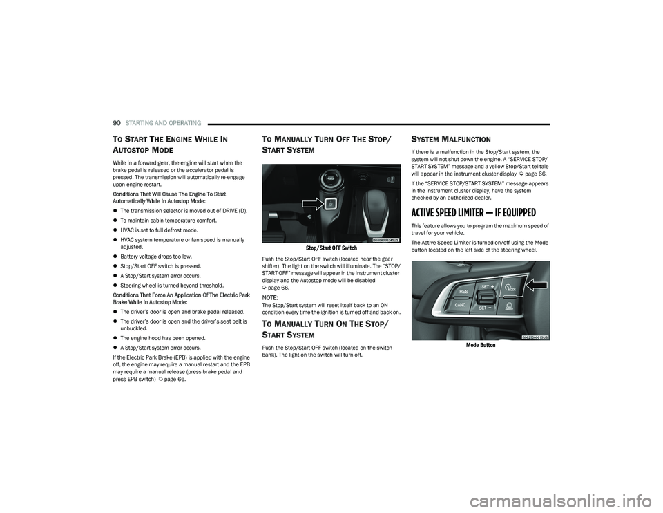
Stop/Start OFF Switch
Push the Stop/Start OFF switch (located near the gear
shifter). The light on the switch will illuminate. The “STOP/
START OFF” message will appear in the instrument cluster
display and the Autostop mode will be disabled
Úpage 66.
NOTE:The Stop/Start system will reset itself back to an ON
condition every time the ignition is turned off and back on.
TO MANUALLY TURN ON THE STOP/
S
TART SYSTEM
Push the Stop/Start OFF switch (located on the switch
bank). The light on the switch will turn off.
SYSTEM MALFUNCTION
If there is a malfunction in the Stop/Start system, the
system will not shut down the engine. A “SERVICE STOP/
START SYSTEM” message and a yellow Stop/Start telltale
will appear in the instrument cluster display
Úpage 66.
If the “SERVICE STOP/START SYSTEM” message appears
in the instrument cluster display, have the system
checked by an authorized dealer.
ACTIVE SPEED LIMITER — IF EQUIPPED
This feature allows you to program the maximum speed of
travel for your vehicle.
The Active Speed Limiter is turned on/off using the Mode
button located on the left side of the steering wheel.
Mode Button
23_GG_OM_EN_USC_t.book Page 90