DODGE JOURNEY 2017 1.G Owners Manual
Manufacturer: DODGE, Model Year: 2017, Model line: JOURNEY, Model: DODGE JOURNEY 2017 1.GPages: 510
Page 461 of 510
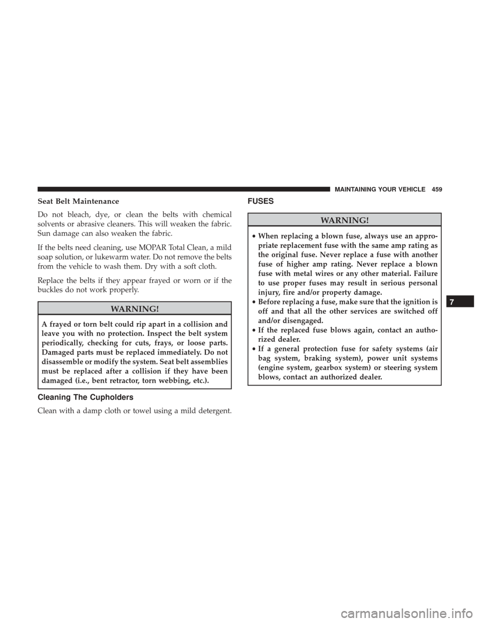
Seat Belt Maintenance
Do not bleach, dye, or clean the belts with chemical
solvents or abrasive cleaners. This will weaken the fabric.
Sun damage can also weaken the fabric.
If the belts need cleaning, use MOPAR Total Clean, a mild
soap solution, or lukewarm water. Do not remove the belts
from the vehicle to wash them. Dry with a soft cloth.
Replace the belts if they appear frayed or worn or if the
buckles do not work properly.
WARNING!
A frayed or torn belt could rip apart in a collision and
leave you with no protection. Inspect the belt system
periodically, checking for cuts, frays, or loose parts.
Damaged parts must be replaced immediately. Do not
disassemble or modify the system. Seat belt assemblies
must be replaced after a collision if they have been
damaged (i.e., bent retractor, torn webbing, etc.).
Cleaning The Cupholders
Clean with a damp cloth or towel using a mild detergent.
FUSES
WARNING!
•When replacing a blown fuse, always use an appro-
priate replacement fuse with the same amp rating as
the original fuse. Never replace a fuse with another
fuse of higher amp rating. Never replace a blown
fuse with metal wires or any other material. Failure
to use proper fuses may result in serious personal
injury, fire and/or property damage.
• Before replacing a fuse, make sure that the ignition is
off and that all the other services are switched off
and/or disengaged.
• If the replaced fuse blows again, contact an autho-
rized dealer.
• If a general protection fuse for safety systems (air
bag system, braking system), power unit systems
(engine system, gearbox system) or steering system
blows, contact an authorized dealer.
7
MAINTAINING YOUR VEHICLE 459
Page 462 of 510
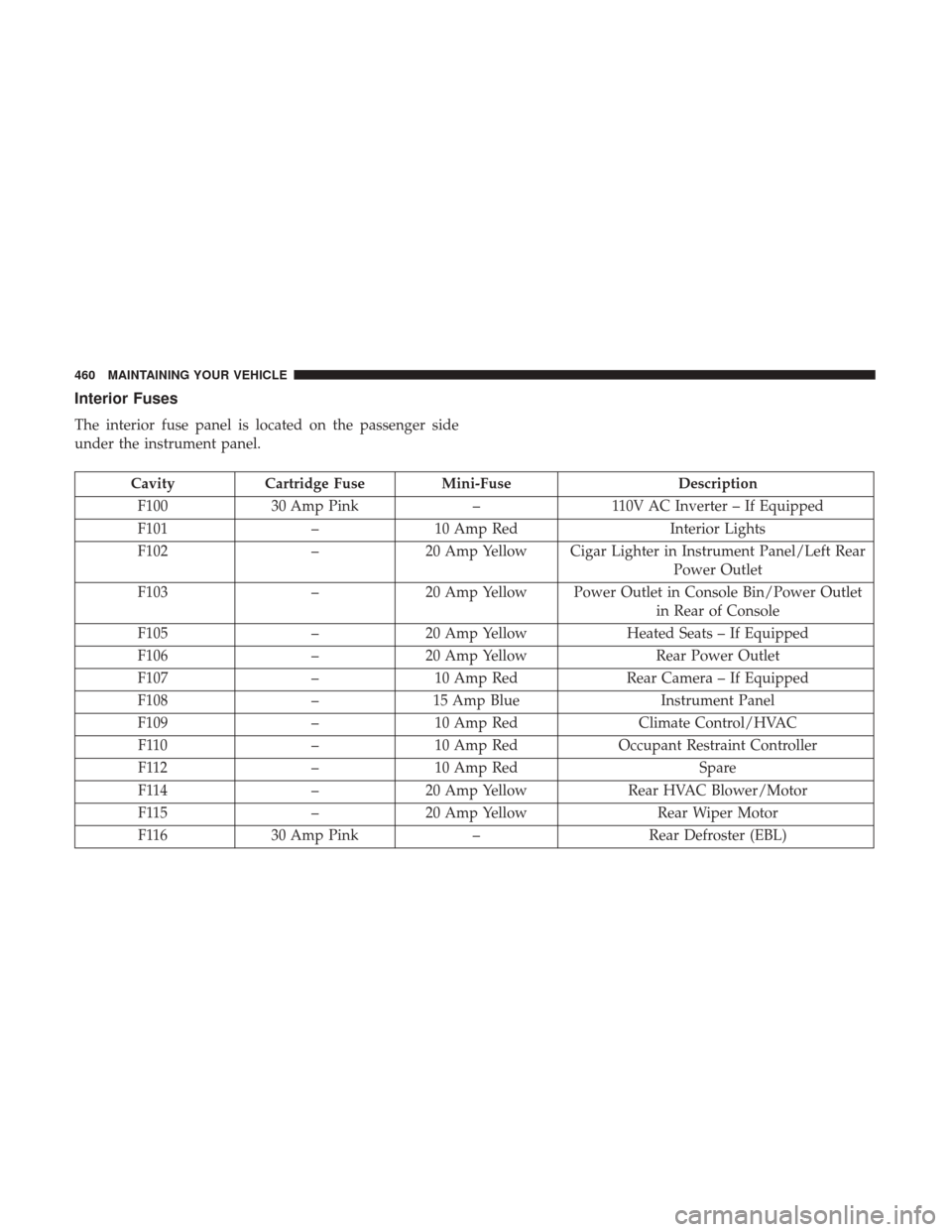
Interior Fuses
The interior fuse panel is located on the passenger side
under the instrument panel.
CavityCartridge Fuse Mini-Fuse Description
F100 30 Amp Pink –110V AC Inverter – If Equipped
F101 –10 Amp Red Interior Lights
F102 –20 Amp Yellow Cigar Lighter in Instrument Panel/Left Rear
Power Outlet
F103 –20 Amp Yellow Power Outlet in Console Bin/Power Outlet
in Rear of Console
F105 –20 Amp Yellow Heated Seats – If Equipped
F106 –20 Amp Yellow Rear Power Outlet
F107 –10 Amp Red Rear Camera – If Equipped
F108 –15 Amp Blue Instrument Panel
F109 –10 Amp Red Climate Control/HVAC
F110 –10 Amp Red Occupant Restraint Controller
F112 –10 Amp Red Spare
F114 –20 Amp Yellow Rear HVAC Blower/Motor
F115 –20 Amp Yellow Rear Wiper Motor
F116 30 Amp Pink –Rear Defroster (EBL)
460 MAINTAINING YOUR VEHICLE
Page 463 of 510
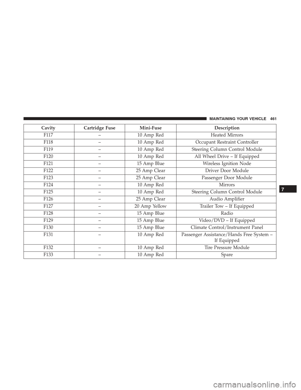
CavityCartridge Fuse Mini-Fuse Description
F117 –10 Amp Red Heated Mirrors
F118 –10 Amp Red Occupant Restraint Controller
F119 –10 Amp Red Steering Column Control Module
F120 –10 Amp Red All Wheel Drive – If Equipped
F121 –15 Amp Blue Wireless Ignition Node
F122 –25 Amp Clear Driver Door Module
F123 –25 Amp Clear Passenger Door Module
F124 –10 Amp Red Mirrors
F125 –10 Amp Red Steering Column Control Module
F126 –25 Amp Clear Audio Amplifier
F127 –20 Amp Yellow Trailer Tow – If Equipped
F128 –15 Amp Blue Radio
F129 –15 Amp Blue Video/DVD – If Equipped
F130 –15 Amp Blue Climate Control/Instrument Panel
F131 –10 Amp Red Passenger Assistance/Hands Free System –
If Equipped
F132 –10 Amp Red Tire Pressure Module
F133 –10 Amp Red Spare
7
MAINTAINING YOUR VEHICLE 461
Page 464 of 510
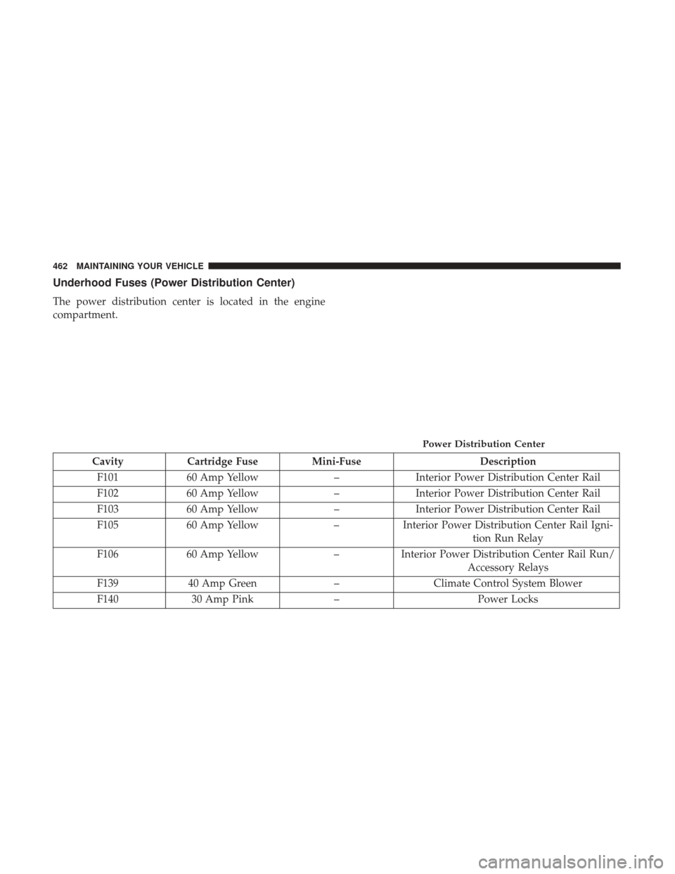
Underhood Fuses (Power Distribution Center)
The power distribution center is located in the engine
compartment.
CavityCartridge Fuse Mini-Fuse Description
F101 60 Amp Yellow –Interior Power Distribution Center Rail
F102 60 Amp Yellow –Interior Power Distribution Center Rail
F103 60 Amp Yellow –Interior Power Distribution Center Rail
F105 60 Amp Yellow –Interior Power Distribution Center Rail Igni-
tion Run Relay
F106 60 Amp Yellow –Interior Power Distribution Center Rail Run/
Accessory Relays
F139 40 Amp Green –Climate Control System Blower
F140 30 Amp Pink – Power Locks
Power Distribution Center
462 MAINTAINING YOUR VEHICLE
Page 465 of 510
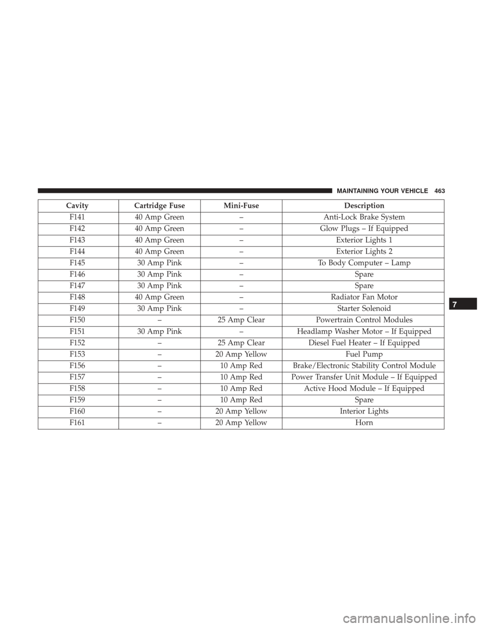
CavityCartridge Fuse Mini-Fuse Description
F141 40 Amp Green –Anti-Lock Brake System
F142 40 Amp Green –Glow Plugs – If Equipped
F143 40 Amp Green –Exterior Lights 1
F144 40 Amp Green –Exterior Lights 2
F145 30 Amp Pink –To Body Computer – Lamp
F146 30 Amp Pink – Spare
F147 30 Amp Pink – Spare
F148 40 Amp Green –Radiator Fan Motor
F149 30 Amp Pink –Starter Solenoid
F150 –25 Amp Clear Powertrain Control Modules
F151 30 Amp Pink –Headlamp Washer Motor – If Equipped
F152 –25 Amp Clear Diesel Fuel Heater – If Equipped
F153 –20 Amp Yellow Fuel Pump
F156 –10 Amp Red Brake/Electronic Stability Control Module
F157 –10 Amp Red Power Transfer Unit Module – If Equipped
F158 –10 Amp Red Active Hood Module – If Equipped
F159 –10 Amp Red Spare
F160 –20 Amp Yellow Interior Lights
F161 –20 Amp Yellow Horn
7
MAINTAINING YOUR VEHICLE 463
Page 466 of 510
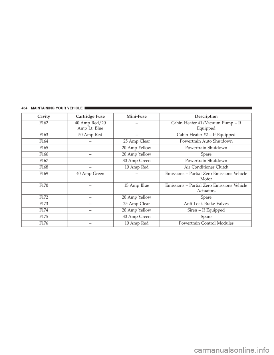
CavityCartridge Fuse Mini-Fuse Description
F162 40 Amp Red/20
Amp Lt. Blue –
Cabin Heater #1/Vacuum Pump – If
Equipped
F163 50 Amp Red –Cabin Heater #2 – If Equipped
F164 –25 Amp Clear Powertrain Auto Shutdown
F165 –20 Amp Yellow Powertrain Shutdown
F166 –20 Amp Yellow Spare
F167 –30 Amp Green Powertrain Shutdown
F168 –10 Amp Red Air Conditioner Clutch
F169 40 Amp Green –Emissions – Partial Zero Emissions Vehicle
Motor
F170 –15 Amp Blue Emissions – Partial Zero Emissions Vehicle
Actuators
F172 –20 Amp Yellow Spare
F173 –25 Amp Clear Anti Lock Brake Valves
F174 –20 Amp Yellow Siren – If Equipped
F175 –30 Amp Green Spare
F176 –10 Amp Red Powertrain Control Modules
464 MAINTAINING YOUR VEHICLE
Page 467 of 510
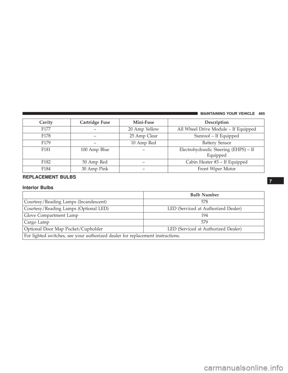
CavityCartridge Fuse Mini-Fuse Description
F177 –20 Amp Yellow All Wheel Drive Module – If Equipped
F178 –25 Amp Clear Sunroof – If Equipped
F179 –10 Amp Red Battery Sensor
F181 100 Amp Blue –Electrohydraulic Steering (EHPS) – If
Equipped
F182 50 Amp Red –Cabin Heater #3 – If Equipped
F184 30 Amp Pink –Front Wiper Motor
REPLACEMENT BULBS
Interior Bulbs
Bulb Number
Courtesy/Reading Lamps (Incandescent) 578
Courtesy/Reading Lamps (Optional LED) LED (Serviced at Authorized Dealer)
Glove Compartment Lamp 194
Cargo Lamp 579
Optional Door Map Pocket/Cupholder LED (Serviced at Authorized Dealer)
For lighted switches, see your authorized dealer for replacement instructions.
7
MAINTAINING YOUR VEHICLE 465
Page 468 of 510
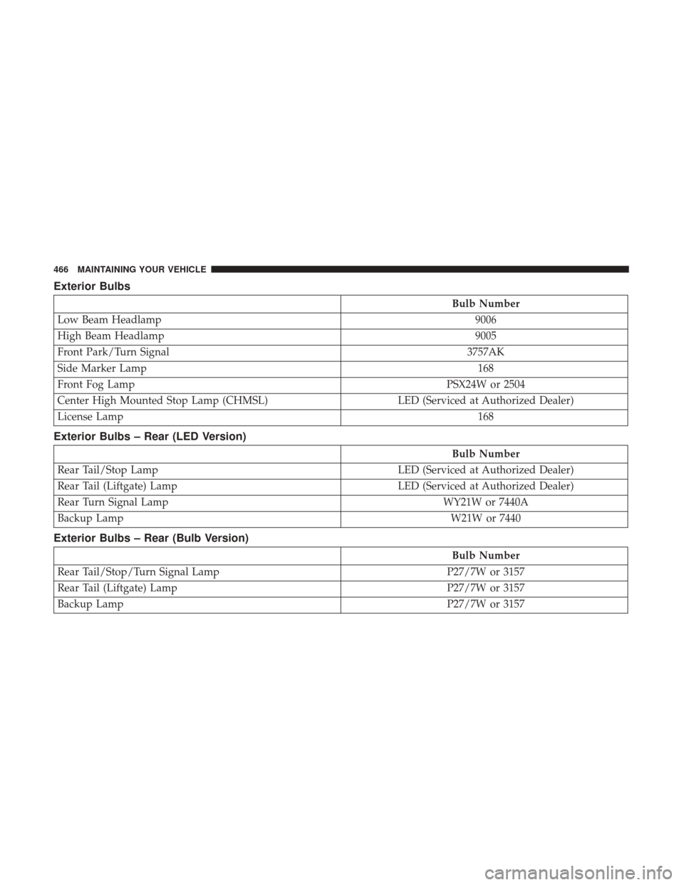
Exterior Bulbs
Bulb Number
Low Beam Headlamp 9006
High Beam Headlamp 9005
Front Park/Turn Signal 3757AK
Side Marker Lamp 168
Front Fog Lamp PSX24W or 2504
Center High Mounted Stop Lamp (CHMSL) LED (Serviced at Authorized Dealer)
License Lamp 168
Exterior Bulbs – Rear (LED Version)
Bulb Number
Rear Tail/Stop Lamp LED (Serviced at Authorized Dealer)
Rear Tail (Liftgate) Lamp LED (Serviced at Authorized Dealer)
Rear Turn Signal Lamp WY21W or 7440A
Backup Lamp W21W or 7440
Exterior Bulbs – Rear (Bulb Version)
Bulb Number
Rear Tail/Stop/Turn Signal Lamp P27/7W or 3157
Rear Tail (Liftgate) Lamp P27/7W or 3157
Backup Lamp P27/7W or 3157
466 MAINTAINING YOUR VEHICLE
Page 469 of 510
BULB REPLACEMENT
NOTE:Lens fogging can occur under certain atmospheric
conditions. This will usually clear as atmospheric condi-
tions change to allow the condensation to change back into
a vapor. Turning the lamps on will usually accelerate the
clearing process.
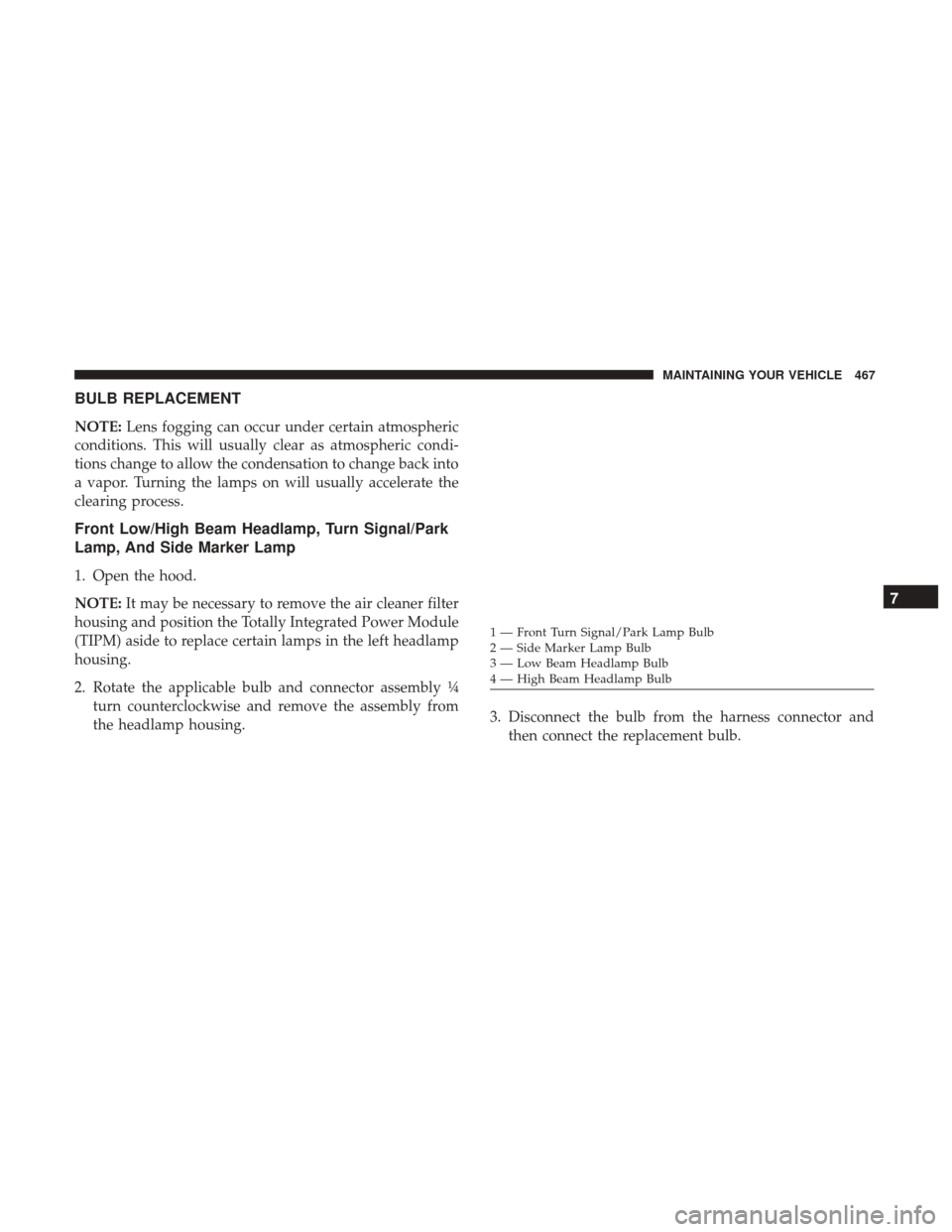
Front Low/High Beam Headlamp, Turn Signal/Park
Lamp, And Side Marker Lamp
1. Open the hood.
NOTE: It may be necessary to remove the air cleaner filter
housing and position the Totally Integrated Power Module
(TIPM) aside to replace certain lamps in the left headlamp
housing.
2. Rotate the applicable bulb and connector assembly ¼ turn counterclockwise and remove the assembly from
the headlamp housing. 3. Disconnect the bulb from the harness connector and
then connect the replacement bulb.
1 — Front Turn Signal/Park Lamp Bulb
2 — Side Marker Lamp Bulb
3 — Low Beam Headlamp Bulb
4 — High Beam Headlamp Bulb
7
MAINTAINING YOUR VEHICLE 467
Page 470 of 510
CAUTION!
Do not touch the new bulb with your fingers. Oil
contamination will severely shorten bulb life. If the
bulb comes in contact with any oily surface, clean the
bulb with rubbing alcohol.
4. Install the bulb and connector assembly into the head- lamp housing and rotate it ¼ turn clockwise to lock it in
place.
Front Fog Lamp
NOTE: Turn the steering wheel to the right if replacing the
left front fog lamp or to the left if replacing the right front
fog lamp to allow for easier access to the front of the wheel
well.
1. Remove the fasteners retaining the front lower wheel well access panel and remove the access panel.
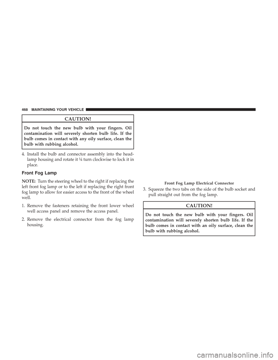
2. Remove the electrical connector from the fog lamp housing. 3. Squeeze the two tabs on the side of the bulb socket and
pull straight out from the fog lamp.
CAUTION!
Do not touch the new bulb with your fingers. Oil
contamination will severely shorten bulb life. If the
bulb comes in contact with an oily surface, clean the
bulb with rubbing alcohol.
Front Fog Lamp Electrical Connector
468 MAINTAINING YOUR VEHICLE