jump start DODGE JOURNEY 2020 Owners Manual
[x] Cancel search | Manufacturer: DODGE, Model Year: 2020, Model line: JOURNEY, Model: DODGE JOURNEY 2020Pages: 396, PDF Size: 25.53 MB
Page 7 of 396
5
JACKING AND TIRE CHANGING........................ 199
Jack Location .. ...........................................199
Spare Tire Location And Removal . . ..........200
Preparations For Jacking. . .........................201
Jacking Instructions . . .................................201
Road Tire Installation . . ..............................205
Spare Tire Stowage. . ..................................206
JUMP STARTING ................................................ 2 0 6
Preparations For Jump Start .. ...................207
Jump Starting Procedure. . .........................208
IF YOUR ENGINE OVERHEATS . . ....................... 209
2.4L Engine — If Equipped .. ...................... 210
GEAR SELECTOR OVERRIDE . . .......................... 210
FREEING A STUCK VEHICLE .. ........................... 211
TOWING A DISABLED VEHICLE .. ...................... 212
Front-Wheel Drive (FWD) Models.. ............213
Tow Eye Usage — If Equipped . . ................213
ENHANCED ACCIDENT RESPONSE
SYSTEM (EARS) . .
............................................... 215
EVENT DATA RECORDER (EDR) .. ..................... 215
SERVICING AND MAINTENANCE
SCHEDULED SERVICING ................................... 216
Maintenance Plan.. ....................................217
ENGINE COMPARTMENT . . ................................ 220
2.4L Engine .. ..............................................220
Checking Oil Level . . ................................... 221
Adding Washer Fluid . . ...............................221
Maintenance-Free Battery . . ...................... 221
Pressure Washing . . ....................................222 DEALER SERVICE .
.
............................................222
Engine Oil .................................................. 223
E ngine Oil Filter . . ........................................ 224
Engine Air Cleaner Filter . . ......................... 224
Air Conditioner Maintenance . . ................. 224
Accessory Drive Belt Inspection . . ............. 225
Body Lubrication . . ...................................... 226
Windshield Wiper Blades . . ........................ 226
Exhaust System . . ...................................... 227
Cooling System . . ....................................... 228
Brake System . . .......................................... 232
Automatic Transmission. . .......................... 233
RAISING THE VEHICLE . . .....................................234
TIRES....................................................................234 T ire Safety Information .. ........................... 234
Tires — General Information . . .................. 242
Tire Types . .................................................. 246
S pare Tires — If Equipped . . ....................... 247
Wheel And Wheel Trim Care . . .................. 249
Tire Chains and Traction Devices . . ........... 250
Tire Rotation Recommendations . . ........... 251
DEPARTMENT OF TRANSPORTATION UNIFORM
TIRE QUALITY GRADES . .
...................................251
Treadwear .................................................. 251
T raction Grades . . ....................................... 251
Temperature Grades . . ............................... 252
BODYWORK . . ...................................................... 252
Protection From Atmospheric Agents..
..... 252
Body And Underbody Maintenance . . ........ 253
Preserving The Bodywork . . ........................ 253INTERIORS .
.
....................................................... 254
Seats And Fabric Parts .. ............................ 254
Plastic And Coated Parts. . ......................... 254
Leather Parts . . ........................................... 255
Glass Surfaces . . ........................................ 255
Cleaning The Cupholders . . ....................... 255
TECHNICAL SPECIFICATIONS
IDENTIFICATION DATA ...................................... 256
Vehicle Identification Number .. ................ 256
BRAKE SYSTEM . . ............................................... 256
WHEEL AND TIRE TORQUE
SPECIFICATIONS ..
.............................................. 257
Torque Specifications.. .............................. 257
FUEL REQUIREMENTS . . .................................... 257
Reformulated Gasoline .. .......................... 258
Materials Added To Fuel . . ......................... 258
Gasoline/Oxygenate Blends . . ................... 258
Do Not Use E-85 In Non-Flex Fuel
Vehicles . ..................................................... 259
C
NG And LP Fuel System Modifications . . 259
MMT In Gasoline. . ...................................... 259
Fuel System Cautions. . .............................. 259
Carbon Monoxide Warnings. . .................... 260
FLUID CAPACITIES . . ........................................... 261
FLUIDS AND LUBRICANTS .. .............................. 262
Engine ....................................................... 262
C hassis . ..................................................... 264
Page 161 of 396
STARTING AND OPERATING 159
(Continued)
COLD WEATHER OPERATION
(B
ELOW –22°F OR −30°C)
To ensure reliable starting at these
temperatures, use of an externally powered
electric engine block heater (available from an
authorized dealer) is recommended.
IF ENGINE FAILS TO START
If the engine fails to start after you have
followed the "Normal Starting" or "Cold Weather
Operation" procedure it may be flooded. Push
the accelerator pedal all the way to the floor and
hold it there. Crank the engine for no more than
15 seconds. This should clear any excess fuel in
case the engine is flooded. Leave the ignition
key in the RUN position, release the accelerator
pedal and repeat the “Normal Starting”
procedure.
AFTER STARTING
The idle speed is controlled automatically, and
it will decrease as the engine warms up.
ENGINE BLOCK HEATER — IF EQUIPPED
The engine block heater warms the engine, and
permits quicker starts in cold weather. Connect
the cord to a standard 110-115 Volt AC
electrical outlet with a grounded, three-wire
extension cord.
The engine block heater must be plugged in at
le
ast one hour to have an adequate effect on
the engine.
The engine block heater cord is bundled under
t h
e hood between the headlight assembly and
the Totally Integrated Power Module (Fuse Box)
on the driver's side of the vehicle.
WARNING!
Never pour fuel or other flammable liquid
into the throttle body air inlet opening in an
attempt to start the vehicle. This could
result in flash fire causing serious personal
injury.
Do not attempt to push or tow your vehicle
to get it started. Vehicles equipped with an
automatic transmission cannot be started
this way. Unburned fuel could enter the
catalytic converter and once the engine has
started, ignite and damage the converter
and vehicle.
If the vehicle has a discharged battery,
booster cables may be used to obtain a
start from a booster battery or the battery in
another vehicle. This type of start can be
dangerous if done improperly. Refer to
“Jump Starting Procedure” in “In Case Of
Emergency” for further information.
CAUTION!
To prevent damage to the starter, do not
continuously crank the engine for more than
25 seconds at a time. Wait 60 seconds
before trying again.
WARNING! (Continued)
WARNING!
Remember to disconnect the engine block
heater cord before driving. Damage to the
110-115 Volt electrical cord could cause
electrocution.
5
Page 208 of 396
206 IN CASE OF EMERGENCY
Vehicles Without Wheel Covers
1. Mount the road tire on the axle.
2. I nstall the remaining lug nuts with the cone
s
haped end of the nut toward the wheel.
Lightly tighten the lug nuts.
3. Lo wer the vehicle to the ground by turning
t
he jack handle counterclockwise.
4. F inish tightening the lug nuts. Push down on
t
he wrench while at the end of the handle
for increased leverage. Tighten the lug nuts
in a star pattern until each nut has been
tightened twice. For proper lug nut torque,
refer to “Wheel And Tire Torque Specifi -
cations” in “Technical Specifications”. If in
d o
ubt about the correct tightness, have
them checked with a torque wrench by an
authorized dealer or service station.
5. A
fter 25
miles (40 km), check the lug nut torque
wi
th a torque wrench to ensure that all lug nuts
are properly seated against the wheel.
SPARE TIRE STOWAGE
NOTE:
Refer to “Spare Tire Location And Removal” in
t h
is section, for information on assembling the
winch tools.
1. P lace the spare tire near the winch cable.
H
old the spare upright so that the tire's
tread is on the ground and the valve stem
is at the top of the wheel facing away from
the rear of the vehicle.
2. T ilt the retainer at the end of the winch
c
able and drop it through the center of the
wheel. Then place the spare tire with the
cable and retainer underneath the vehicle.
3. Fit the assembled jack-handle over the winch d
rive nut. Rotate the jack-handle assembly
clockwise to raise the spare tire into the storage
area. Continue to rotate the jack-handle
assembly until you hear the winch mechanism
click three times. It cannot be over tightened.
Push against the tire several times to be sure it
is held securely in place.
JUMP STARTING
If your vehicle has a discharged battery, it can
be jump started using a set of jumper cables
and a battery in another vehicle, or by using a
portable battery booster pack. Jump starting
can be dangerous if done improperly, so please
follow the procedures in this section carefully.
NOTE:
When using a portable battery booster pack,
f o
llow the manufacturer's operating instruc -
tions and precautions.
WARNING!
To avoid the risk of forcing the vehicle off the
jack, do not tighten the wheel nuts fully until
the vehicle has been lowered. Failure to follow
this warning may result in serious injury.
WARNING!
Do not attempt jump starting if the battery is
frozen. It could rupture or explode and cause
personal injury.
CAUTION!
Do not use a portable battery booster pack or
any other booster source with a system
voltage greater than 12 Volts or damage to
the battery, starter motor, alternator or
electrical system may occur.
Page 209 of 396
IN CASE OF EMERGENCY 207
(Continued)
PREPARATIONS FOR JUMP START
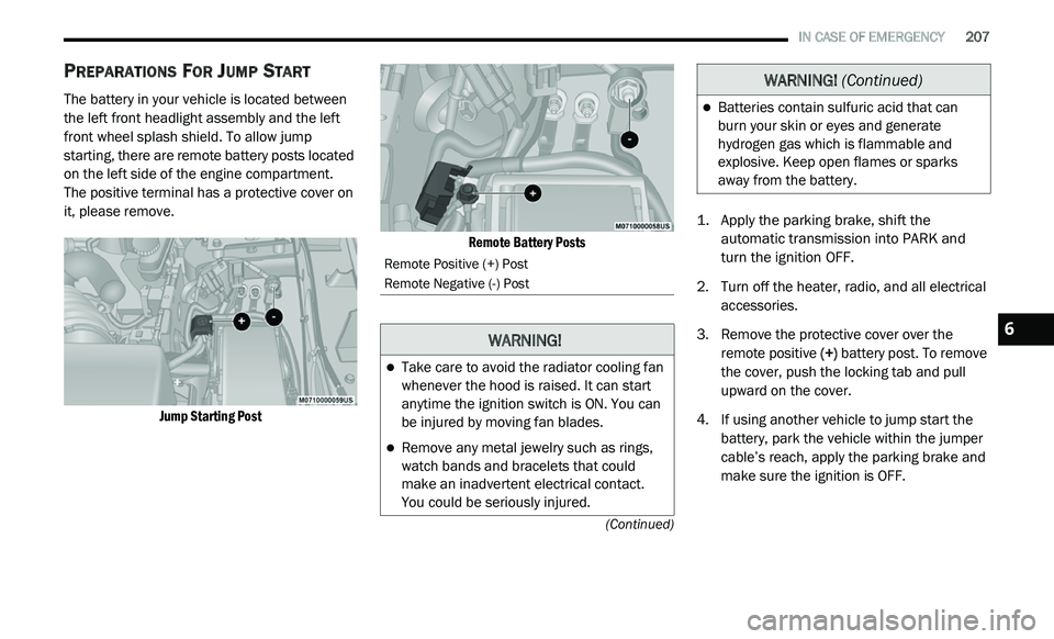
The battery in your vehicle is located between
the left front headlight assembly and the left
front wheel splash shield. To allow jump
starting, there are remote battery posts located
on the left side of the engine compartment.
The positive terminal has a protective cover on
i t
, please remove.
Jump Starting Post Remote Battery Posts
1. Ap
ply the parking brake, shift the
a
utomatic transmission into PARK and
turn the ignition OFF.
2. T urn off the heater, radio, and all electrical
a
ccessories.
3. R emove the protective cover over the
r
emote positive (+) battery post. To remove
the cover, push the locking tab and pull
upward on the cover.
4. If using another vehicle to jump start the b
attery, park the vehicle within the jumper
cable’s reach, apply the parking brake and
make sure the ignition is OFF.
Remote Positive (+) Post
Remote Negative (-) Post
WARNING!
Take care to avoid the radiator cooling fan
whenever the hood is raised. It can start
anytime the ignition switch is ON. You can
be injured by moving fan blades.
Remove any metal jewelry such as rings,
watch bands and bracelets that could
make an inadvertent electrical contact.
You could be seriously injured.
Batteries contain sulfuric acid that can
burn your skin or eyes and generate
hydrogen gas which is flammable and
explosive. Keep open flames or sparks
away from the battery.
WARNING! (Continued)
6
Page 210 of 396
208 IN CASE OF EMERGENCY
JUMP STARTING PROCEDURE
Connecting The Jumper Cables
1. C onnect the positive
(
+) end of the jumper
cable to the remote positive (+)
post of the
discharged vehicle.
2. C onnect the opposite end of the positive (
+)
jumper cable to the positive (+) post of the
booster battery.
3. C onnect the negative end (
-) of the jumper
cable to the negative (-) post of the booster
battery.
4. C onnect the opposite end of the negative (
-)
jumper cable to a good engine ground.
A “ground” is an exposed metallic/
u n
painted part of the engine, frame or
chassis, such as an accessory bracket or
large bolt. The ground must be away from
the battery and fuel injection system. 5. S
tart the engine in the vehicle that has the
b
ooster battery, let the engine idle a few
minutes, and then start the engine in the
vehicle with the discharged battery.
6. Once the engine is started, follow the d
isconnecting procedure below.
WARNING!
Do not allow vehicles to touch each other as
this could establish a ground connection and
personal injury could result.
WARNING!
Failure to follow this jump starting procedure
could result in personal injury or property
damage due to battery explosion.
CAUTION!
Failure to follow these procedures could
result in damage to the charging system of
the booster vehicle or the discharged vehicle.
WARNING!
Do not connect the jumper cable to the
negative (-) post of the discharged battery.
The resulting electrical spark could cause
the battery to explode and could result in
p e
rsonal injury.
Page 211 of 396
IN CASE OF EMERGENCY 209
Disconnecting The Jumper Cables
1. D isconnect the negative
(-)
jumper cable
from the remote negative (-)
post of the
vehicle with the discharged battery.
2. D isconnect the negative end (
-) of the
jumper cable from the negative (-) post of
the booster battery.
3. D isconnect the opposite end of the
p
ositive (+)
jumper cable from the
positive (+)
post of the booster battery.
4. D isconnect the positive (
+) end of the
jumper cable from the remote positive (+)
post of the discharged vehicle.
5. R einstall the protective cover over the
r
emote positive (+) battery post of the
discharged vehicle.
If frequent jump starting is required to start
your vehicle, you should have the battery and
c h
arging system inspected at an authorized
dealer.
IF YOUR ENGINE OVERHEATS
In any of the following situations, you can
reduce the potential for overheating by taking
the appropriate action.
On the highways — slow down.
In city traffic — while stopped, place the trans -
mission in NEUTRAL, but do not increase the
e n
gine idle speed while preventing vehicle
motion with the brakes. NOTE:
There are steps that you can take to slow down
an
impending overheat condition:
If your Air Conditioner (A/C) is on, turn it off.
The A/C system adds heat to the engine
cooling system and turning the A/C off can
help remove this heat.
You can also turn the temperature control to
maximum heat, the mode control to floor and
the blower control to high. This allows the
heater core to act as a supplement to the
radiator and aids in removing heat from the
engine cooling system.
CAUTION!
Accessories plugged into the vehicle power
outlets draw power from the vehicle’s battery,
even when not in use (i.e., cellular devices,
etc.). Eventually, if plugged in long enough
without engine operation, the vehicle’s battery
will discharge sufficiently to degrade battery
life and/or prevent the engine from starting.
WARNING!
You or others can be badly burned by hot
engine coolant (antifreeze) or steam from
your radiator. If you see or hear steam coming
from under the hood, do not open the hood
until the radiator has had time to cool. Never
try to open a cooling system pressure cap
when the radiator or coolant bottle is hot.
6
Page 222 of 396
220 SERVICING AND MAINTENANCE
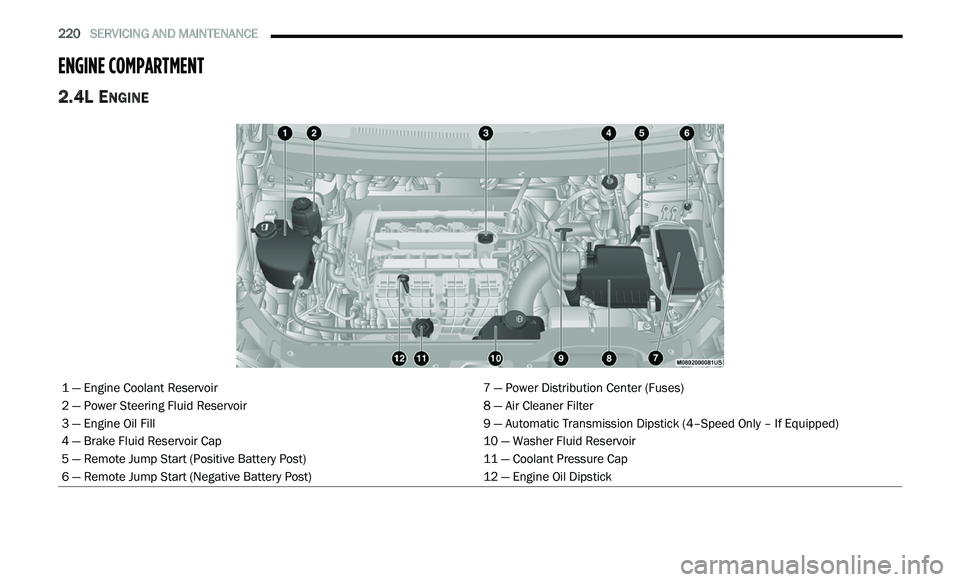
ENGINE COMPARTMENT
2.4L ENGINE
1 — Engine Coolant Reservoir 7 — Power Distribution Center (Fuses)
2 — Power Steering Fluid Reservoir 8 — Air Cleaner Filter
3 — Engine Oil Fill 9 — Automatic Transmission Dipstick (4–Speed Only – If Equipped)
4 — Brake Fluid Reservoir Cap 10 — Washer Fluid Reservoir
5 — Remote Jump Start (Positive Battery Post) 11 — Coolant Pressure Cap
6 — Remote Jump Start (Negative Battery Post) 12 — Engine Oil Dipstick
Page 223 of 396
SERVICING AND MAINTENANCE 221
CHECKING OIL LEVEL
To ensure proper engine lubrication, the engine
oil must be maintained at the correct level.
Check the oil level at regular intervals, such as
every fuel stop. The best time to check the
engine oil level is about five minutes after a fully
warmed engine is shut off. Checking engine oil
level when the engine is cold will give you an
incorrect reading.
Checking the oil while the vehicle is on level
gr
ound and only when the engine is hot, will
improve the accuracy of the oil level readings.
Maintain the oil level between the range
markings on the dipstick. Either the range
markings consist of a crosshatch zone marked
SAFE or a crosshatch zone marked with MIN at
the low end of the range and MAX at the high
end of the range. Adding 1 Quart (1 Liter) of oil
when the reading is at the low end of the range
marking will raise the oil level to the high end of
the range marking.
ADDING WASHER FLUID
The windshield washer and the rear window
washer share the same fluid reservoir. The fluid
reservoir is located in the engine compartment.
Be sure to check the fluid level in the reservoir
at regular intervals. Fill the reservoir with
windshield washer solvent (not radiator
antifreeze) and operate the system for a few
seconds to flush out the residual water.
When refilling the washer fluid reservoir, apply
s o
me washer fluid to a cloth or towel and wipe
the wiper blades clean. This will help blade
performance.
To prevent freeze-up of your windshield washer
s y
stem in cold weather, select a solution or
mixture that meets or exceeds the temperature
range of your climate. This rating information
can be found on most washer fluid containers. The fluid reservoir will hold nearly 1 Gallon
(4 Liters) of washer fluid when the message
“ Lo
WASH” appears in the instrument cluster.
MAINTENANCE-FREE BATTERY
Your vehicle is equipped with a maintenance-free
battery. You will never have to add water, nor is
periodic maintenance required.
NOTE:
The battery is stored in a compartment that is
lo
cated behind the left front fender and is
accessible through the wheel well. The wheel
and tire assembly do not need to be removed to
access the compartment. Remote battery termi -
nals are located in the engine compartment for
j u
mp starting. Refer to “Jump Starting Proce -
dure” in “In Case Of Emergency” for further
i n
formation.
CAUTION!
Do not overfill the engine with oil. Overfilling
the engine with oil will cause oil aeration,
which can lead to loss of oil pressure and an
increase in oil temperature. This loss of oil
pressure and increased oil temperature could
damage your engine.
WARNING!
Commercially available windshield washer
solvents are flammable. They could ignite and
burn you. Care must be exercised when filling
or working around the washer solution.
7
Page 227 of 396

SERVICING AND MAINTENANCE 225
Refrigerant Recovery And Recycling —
R-1234yf
R-1234yf Air Conditioning Refrigerant is a
hydrofluoroolefin (HFO) that is endorsed by
the Environmental Protection Agency and
is an ozone-friendly substance with a low
g l
obal-warming potential. The manufacturer
recommends that air conditioning service be
performed by an authorized dealer using
recovery and recycling equipment.
NOTE:
Use only manufacturer approved A/C system
P A
G compressor oil, and refrigerants.
ACCESSORY DRIVE BELT INSPECTION
When inspecting accessory drive belts, small
cracks that run across the ribbed surface of the
belt from rib to rib, are considered normal.
These are not a reason to replace the belt.
However, cracks running along a rib (not across)
are not normal. Any belt with cracks running
along a rib must be replaced. Also have the belt
replaced if it has excessive wear, frayed cords
or severe glazing.
Accessory Belt (Serpentine Belt)
Conditions that would require replacement:
Rib chunking (one or more ribs has sepa -
rated from belt body)
Rib or belt wear
Longitudinal belt cracking (cracks between
two ribs)
Belt slips
“Groove jumping" (belt does not maintain
correct position on pulley)
Belt broken (Identify and correct problem
before new belt is installed)
Noise (objectionable squeal, squeak, or
rumble is heard or felt while drive belt is in
operation)
CAUTION!
Do not use chemical flushes in your air
conditioning system as the chemicals can
damage your air conditioning components.
Such damage is not covered by the New
Vehicle Limited Warranty.WARNING!
Do not attempt to inspect an accessory
drive belt with vehicle running.
When working near the radiator cooling fan,
disconnect the fan motor lead. The fan is
temperature controlled and can start at any
time regardless of ignition mode. You could
be injured by the moving fan blades.
You can be badly injured working on or
around a motor vehicle. Only do service
work for which you have the knowledge and
the proper equipment. If you have any
doubt about your ability to perform a
service job, take your vehicle to a compe -
tent mechanic.
7
Page 294 of 396
292 MULTIMEDIA
Source
Press the source button to select the desired
au
dio source: “CD,” “AUX” or “USB”. This screen
will time out after a few seconds and return to
the main radio screen if no selection is made.
Info
Press the Info button to display the current
t r
ack information. Press the X button to cancel
this feature.
Shuffle
Press the More... button on the touchscreen then
t h
e Shuffle button on the touchscreen to play the
selections on the compact disc in random order
to provide an interesting change of pace. Press
the Shuffle button on the touchscreen a second
time to turn this feature off.
Audio
Refer to “Audio” in “Radio Mode” for further
i n
formation on adjusting the audio settings.
USB Mode
Overview
USB/iPod® Mode is entered by either inserting a
US
B Jump Drive or an iPod® cable into the USB port,
or by pushing the PLAYER button located left of the
display. Once in Player Mode, press the Source
button, and select “USB/iPod®.”
Inserting USB Device
Gently insert the USB device into the USB Port.
I f
you insert a USB device into the USB port, with
the ignition ON and the radio ON, the unit will
switch to USB mode and begin to play. The
display will show the track number and index
time in minutes and seconds. Play will begin at
the start of track 1.
Seek Up/Down
Press and release the Seek Up button for the
next selection on the USB/iPod® device. Press
a n
d release the Seek Down button to return
to the beginning of the current selection, or
r e
turn to the beginning of the previous selection
if the USB/iPod® device is within the first eight
seconds of the current selection. Fast Seek Up
Press and hold the Seek Up
button on the
touchscreen and the USB/iPod® device will
b e
gin to fast forward through the current track
until the button on the touchscreen is released.
Fast Seek Down
Press and hold the Seek Down button and
the USB/iPod® device will begin to rewind
t h
rough the current track until the button is
released.
Browse
Press the Browse button on the touchscreen to
s e
lect Artist, Albums, Genres, Songs, Playlists or
Folders from the USB/iPod® device. Once the
desired selection is made you can chose from
the available media by pressing the button on
the touchscreen. Press the exit button on the
touchscreen if you wish to cancel the browse
function.
Source
Press the source button on the touchscreen to
s e
lect the desired audio source, CD, AUX, or
USB/iPod®. This screen will time out after a few
seconds and return to the main radio screen if
no selection is made.