remote control DODGE JOURNEY 2020 Owners Manual
[x] Cancel search | Manufacturer: DODGE, Model Year: 2020, Model line: JOURNEY, Model: DODGE JOURNEY 2020Pages: 396, PDF Size: 25.53 MB
Page 8 of 396
6
MULTIMEDIA
CYBERSECURITY ............................................... 265
UCONNECT SETTINGS .. .................................... 266
Customer Programmable
Features — Radio 4.3 Settings. .
................266
Customer Programmable Features —
Uconnect 3/3 NAV Settings .
.
....................274
SAFETY AND GENERAL INFORMATION . . ........ 285
Safety Guidelines .. .....................................285
RADIO 4.3 . .......................................................... 286
I ntroduction .. ..............................................286
Radio Mode . . ..............................................287
Media Mode . . .............................................291
Uconnect Phone (4.3) . . .............................294
More Mode . . ...............................................305
UCONNECT 3/3 NAV WITH 8.4-INCH
DISPLAY . ............................................................. 306
I
ntroduction To the Uconnect 3/3 NAV
With 8.4-Inch Display. .
...............................306
Radio Mode . . ..............................................307
Media Mode . . .............................................316
Uconnect Phone. . .......................................324
Navigation Mode — If Equipped . . ..............339
More Mode . . ...............................................363
STEERING WHEEL AUDIO CONTROLS — IF
EQUIPPED . .
........................................................ 363
Radio Operation .. .......................................364
Media Mode . . .............................................364
IPOD®/USB/MP3 CONTROL . . ......................... 364UCONNECT MULTIMEDIA — VIDEO
ENTERTAINMENT SYSTEM (VES)
(IF EQUIPPED) . .
..................................................365
Getting Started .. ........................................ 365
Single Video Screen. . ................................. 365
Play Video Games . . .................................... 365
Listen To An Audio Source On Channel 2 While
A Video Is Playing On Channel 1 . .
............. 366
Play A DVD Using The Touchscreen
Radio . ......................................................... 367
V
ES Remote Control — If Equipped . . ........ 367
Remote Control Storage . . .......................... 369
Locking The Remote Control. . ................... 369
Replacing The Remote Control
Batteries . .................................................... 369
I
mportant Notes For Single Video Screen
System . ....................................................... 369
U
connect Headphones Operation . . .......... 370
Controls . ..................................................... 370
R eplacing The Headphone Batteries . . ..... 371
Accessibility. . .............................................. 371
Stereo Headphone Lifetime Limited
Warranty . .................................................... 371
S
ystem Information . . ................................. 372
RADIO OPERATION AND MOBILE PHONES . . .. 376
Regulatory And Safety Information.. ......... 377
VOICE COMMAND (UCONNECT 3/3 NAV) .
..... 378
U
connect 3/3 NAV ..................................... 378
U
connect Voice Commands . . .................... 379
CUSTOMER ASSISTANCE
SUGGESTIONS FOR OBTAINING SERVICE FOR
YOUR VEHICLE .................................................. 380
Prepare For The Appointment .. ................ 380
Prepare A List. . ........................................... 380
Be Reasonable With Requests . . ............... 380
IF YOU NEED ASSISTANCE . . ............................ 380
FCA US LLC Customer Center ..
................. 381
FCA Canada Inc. Customer Center . . ......... 381
In Mexico Contact . . .................................... 381
Puerto Rico And US Virgin Islands . . .......... 381
Customer Assistance For The Hearing Or
Speech Impaired (TDD/TTY) . .
................... 381
Service Contract . . ..................................... 381
WARRANTY INFORMATION . . ............................ 382
MOPAR PARTS.. ................................................. 382
REPORTING SAFETY DEFECTS .. ...................... 382
In The 50 United States And
Washington, D.C. . .
..................................... 382
In Canada . .................................................. 383
P
UBLICATION ORDER FORMS . . ...................... 383
Page 16 of 396
14 GETTING TO KNOW YOUR VEHICLE
(Continued)
IGNITION OR ACCESSORY ON MESSAGE
Opening the driver's door when the ignition is in
the ACC or ON (engine not running) position, a
chime will sound to remind you to place the
ignition in the OFF position. In addition to the
chime, the ignition or accessory on message will
display in the cluster.
NOTE:
With the Uconnect system, the power window
s w
itches, radio, power sunroof (if equipped),
and power outlets will remain active for up to
10 minutes after the ignition is placed in the
O F
F position. Opening either front door will
cancel this feature. The time for this feature is
programmable. Refer to “Uconnect Settings” in
“Multimedia” for further information.
REMOTE START — IF EQUIPPED
HOW TO USE REMOTE START
All of the following conditions must be met
before the engine will remote start:
Gear selector in PARK
Doors closed
Hood closed
Liftgate closed
Hazard switch off
Brake switch inactive (brake pedal not pushed)
Battery at an acceptable charge level
System not disabled from previous remote
start event
Vehicle security alarm not active
Ignition in the OFF position
Malfunction Indicator Light (MIL) is not illumi -
nated
WARNING!
Before exiting a vehicle, always shift the
automatic transmission into PARK and
apply the parking brake. Always make sure
the keyless ignition is in the OFF position,
remove the key fob from the vehicle and
lock the vehicle.
Never leave children alone in a vehicle, or
with access to an unlocked vehicle.
Allowing children to be in a vehicle unat -
tended is dangerous for a number of
r e
asons. A child or others could be seriously
or fatally injured. Children should be
warned not to touch the parking brake,
brake pedal or the gear selector.
Do not leave the key fob in or near the
vehicle, or in a location accessible to chil-
dren, and do not leave the ignition of a
v e
hicle equipped with Keyless Enter-N-Go
in the ACC or ON/RUN position. A child
could operate power windows, other
controls, or move the vehicle.
Do not leave children or animals inside parked
vehicles in hot weather. Interior heat build-up
may cause serious injury or death.
CAUTION!
An unlocked vehicle is an invitation for
thieves. Always remove the key fobs from
vehicle, place the ignition in the OFF position
and lock all doors when leaving the vehicle
unattended.
WARNING! (Continued)
Page 17 of 396
GETTING TO KNOW YOUR VEHICLE 15
REMOTE START ABORT MESSAGE
The following messages will appear in the
instrument cluster display if the vehicle fails to
remote start or exits remote start prematurely if
equipped with Remote Start:
Remote Start Cancelled — Door Open
Remote Start Cancelled — Hood Open
Remote Start Cancelled — Fuel Low
Remote Start Cancelled — L/Gate Open
Remote Start Disabled — Start Vehicle To
Reset The message stays active until the ignition is
p
l
aced in the ON/RUN position.
TO ENTER REMOTE START MODE
Push and release the remote start button on the
key fob twice within five seconds. The vehicle
doors will lock, the parking lights will flash and
the horn will chirp twice (if programmed). Then,
the engine will start and the vehicle will remain
in the Remote Start mode for a 15 minute cycle.
NOTE:
If an engine fault is present or fuel level is
low, the vehicle will start and then shut down
in 10 seconds.
The park lamps will turn on and remain on
during Remote Start mode.
For security, power window and power
sunroof operation (if equipped) are disabled
when the vehicle is in the Remote Start
mode.
The engine can be started two consecutive
times (two 15 minute cycles) with the key
f o
b. However, the ignition must be placed in
the ON/RUN position before you can repeat
the start sequence for a third cycle.
TO EXIT REMOTE START MODE
W
ITHOUT DRIVING THE VEHICLE
Push and release the remote start button one
time or allow the engine to run for the entire
15 minute cycle.
NOTE:
To avoid unintentional shutdowns, the system
wi
ll disable for two seconds after receiving a
valid Remote Start request.
TO EXIT REMOTE START MODE AND
D
RIVE THE VEHICLE
Before the end of 15 minute cycle, push and
re
lease the unlock button on the key fob to
unlock the doors and disarm the vehicle
security alarm (if equipped). Then, prior to the
end of the 15 minute cycle, push and release
t h
e START/STOP ignition button.
NOTE:
The message “Push Start Button” will appear in
t h
e instrument cluster display until you push the
START/STOP ignition button.
WARNING!
Do not start or run an engine in a closed
garage or confined area. Exhaust gas
contains Carbon Monoxide (CO) which is
odorless and colorless. Carbon Monoxide is
poisonous and can cause serious injury or
death when inhaled.
Keep key fobs away from children. Opera -
tion of the Remote Start System, windows,
d o
or locks or other controls could cause
serious injury or death.
2
Page 38 of 396
36 GETTING TO KNOW YOUR VEHICLE
The heated steering wheel control button is
located within the Uconnect system. You can
gain access to the control button through the
climate screen or the controls screen.
Press the heated steering wheel button
once to turn the heating element on.
Press the heated steering wheel button a
second time to turn the heating element off.
NOTE:
The engine must be running for the heated
s t
eering wheel to operate.
Vehicles Equipped With Remote Start
On models that are equipped with remote start,
t h
e heated steering wheel can be programmed
to come on during a remote start through the
Uconnect system. Refer to “Uconnect Settings”
in “Multimedia” for further information.
MIRRORS
INSIDE DAY/NIGHT MIRROR — IF
E
QUIPPED
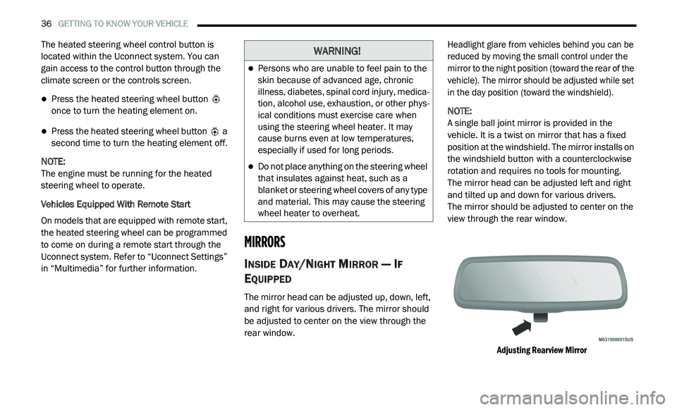
The mirror head can be adjusted up, down, left,
and right for various drivers. The mirror should
be adjusted to center on the view through the
rear window.
Headlight glare from vehicles behind you can be
r
e
duced by moving the small control under the
mirror to the night position (toward the rear of the
vehicle). The mirror should be adjusted while set
in the day position (toward the windshield).
NOTE:
A single ball joint mirror is provided in the
v e
hicle. It is a twist on mirror that has a fixed
position at the windshield. The mirror installs on
the windshield button with a counterclockwise
rotation and requires no tools for mounting.
The mirror head can be adjusted left and right
a n
d tilted up and down for various drivers.
The mirror should be adjusted to center on the
v i
ew through the rear window.
Adjusting Rearview Mirror
WARNING!
Persons who are unable to feel pain to the
skin because of advanced age, chronic
illness, diabetes, spinal cord injury, medica -
tion, alcohol use, exhaustion, or other phys -
ical conditions must exercise care when
u s
ing the steering wheel heater. It may
cause burns even at low temperatures,
especially if used for long periods.
Do not place anything on the steering wheel
that insulates against heat, such as a
blanket or steering wheel covers of any type
and material. This may cause the steering
wheel heater to overheat.
Page 45 of 396
GETTING TO KNOW YOUR VEHICLE 43
INTERIOR LIGHTS
COURTESY/INTERIOR LIGHTING
The interior lights come on when a door is
opened.
To protect the battery, the interior lights will turn
of
f automatically 10 minutes after the ignition is
p l
aced in the OFF position. This will occur if the
interior lights were switched on manually or are
on because a door is open. The battery
protection also includes the glove compartment
light. To restore interior light operation after
automatic battery protection is enabled (lights
off), either place the ignition in the ON/RUN
position or cycle the light switch.
Courtesy Lights
The overhead console has two courtesy lights.
The lights turn on when a front door, a rear door
or the liftgate is opened. If your vehicle is
equipped with Remote Keyless Entry, the lights
will also turn on when the unlock button on the
key fob is pushed. The courtesy lights also
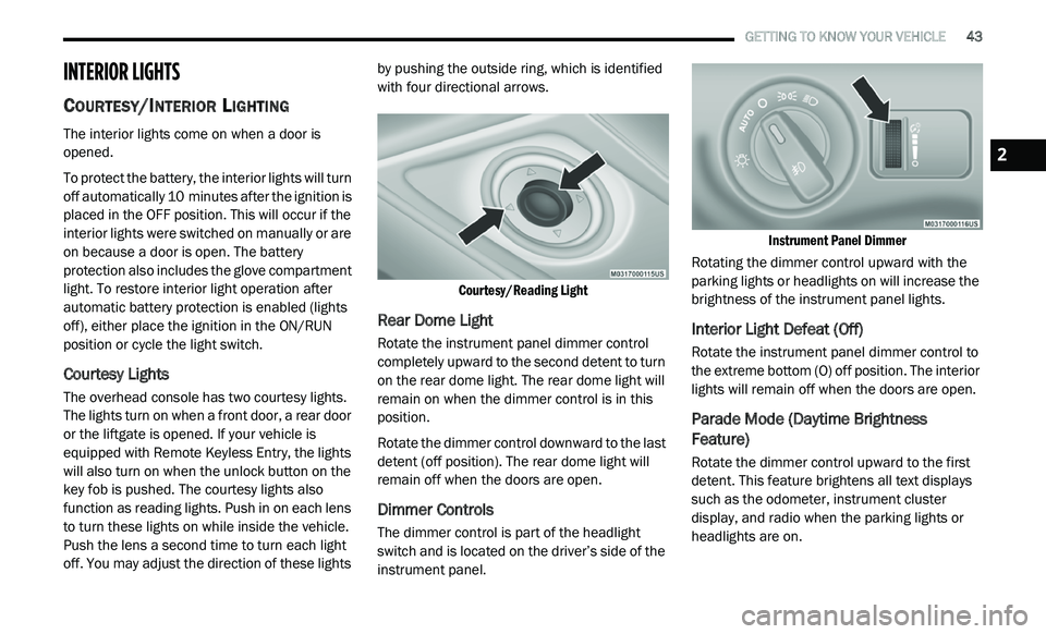
function as reading lights. Push in on each lens
to turn these lights on while inside the vehicle.
Push the lens a second time to turn each light
off. You may adjust the direction of these lights by pushing the outside ring, which is identified
with four directional arrows.
Courtesy/Reading Light
Rear Dome Light
Rotate the instrument panel dimmer control
completely upward to the second detent to turn
on the rear dome light. The rear dome light will
remain on when the dimmer control is in this
position.
Rotate the dimmer control downward to the last
de
tent (off position). The rear dome light will
remain off when the doors are open.
Dimmer Controls
The dimmer control is part of the headlight
switch and is located on the driver’s side of the
instrument panel.
Instrument Panel Dimmer
Rotating the dimmer control upward with the
p a
rking lights or headlights on will increase the
brightness of the instrument panel lights.
Interior Light Defeat (Off)
Rotate the instrument panel dimmer control to
the extreme bottom (O) off position. The interior
lights will remain off when the doors are open.
Parade Mode (Daytime Brightness
Feature)
Rotate the dimmer control upward to the first
detent. This feature brightens all text displays
such as the odometer, instrument cluster
display, and radio when the parking lights or
headlights are on.
2
Page 79 of 396
GETTING TO KNOW YOUR VEHICLE 77
LIFTGATE
OPENING
The liftgate can be unlocked or locked pushing
the unlock or lock button on the Remote
Keyless Entry key fob, the Keyless Enter-N-Go
(Passive Entry) lock/unlock button underneath
the left side of the accent bar, which is located
on the liftgate below the glass, or by activating
the power door lock switch located on either
front door trim panel. Refer to “Keyless Enter-N-Go — Passive Entry” in
“
D
oors” in this chapter for further information
on Keyless Enter-N-Go (Passive Entry).
NOTE:
The liftgate cannot be unlocked or locked with
th
e manual door locks on the door trim panels
or the door lock cylinder on the driver's door.
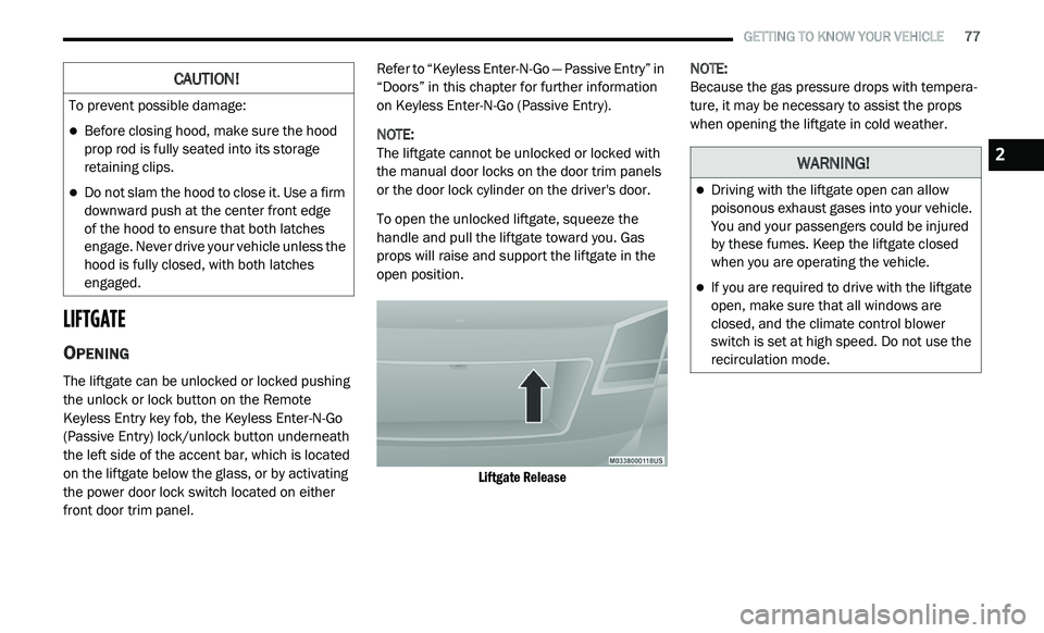
To open the unlocked liftgate, squeeze the
h a
ndle and pull the liftgate toward you. Gas
props will raise and support the liftgate in the
open position.
Liftgate Release
NOTE:
Because the gas pressure drops with tempera -
ture, it may be necessary to assist the props
w h
en opening the liftgate in cold weather.
CAUTION!
To prevent possible damage:
Before closing hood, make sure the hood
prop rod is fully seated into its storage
retaining clips.
Do not slam the hood to close it. Use a firm
downward push at the center front edge
of the hood to ensure that both latches
e n
gage. Never drive your vehicle unless the
hood is fully closed, with both latches
engaged.
WARNING!
Driving with the liftgate open can allow
poisonous exhaust gases into your vehicle.
You and your passengers could be injured
by these fumes. Keep the liftgate closed
when you are operating the vehicle.
If you are required to drive with the liftgate
open, make sure that all windows are
closed, and the climate control blower
switch is set at high speed. Do not use the
recirculation mode.
2
Page 82 of 396
80 GETTING TO KNOW YOUR VEHICLE
GARAGE DOOR OPENER — IF EQUIPPED
HomeLink® replaces up to three remote controls
(hand-held transmitters) that operate devices
such as garage door openers, motorized gates,
lighting or home security systems. The
HomeLink® unit operates off your vehicle’s
battery.
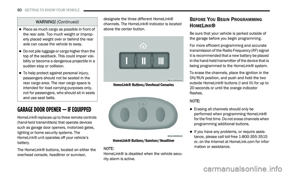
The HomeLink® buttons, located on either the
ov
erhead console, headliner or sunvisor, designate the three different HomeLink®
channels. The HomeLink® indicator is located
above the center button.
HomeLink® Buttons/Overhead Consoles
HomeLink® Buttons/Sunvisor/Headliner
NOTE:
HomeLink® is disabled when the vehicle secu -
rity alarm is active.
BEFORE YOU BEGIN PROGRAMMING
H
OMELINK®
Be sure that your vehicle is parked outside of
the garage before you begin programming.
For more efficient programming and accurate
t r
ansmission of the Radio Frequency (RF) signal
it is recommended that a new battery be placed
in the hand-held transmitter of the device that is
being programmed to the HomeLink® system.
To erase the channels, place the ignition in the
ON
/RUN position, and push and hold the two
outside HomeLink® buttons (I and III) for up to
20 seconds or until the orange indicator
flashes.
NOTE:
Erasing all channels should only be
performed when programming HomeLink®
for the first time. Do not erase channels when
programming additional buttons.
If you have any problems, or require assis -
tance, please call toll-free 1 -
800-355-3515
or, on the Internet at HomeLink.com for infor-
mation or assistance.
Place as much cargo as possible in front of
the rear axle. Too much weight or improp -
erly placed weight over or behind the rear
a x
le can cause the vehicle to sway.
Do not pile luggage or cargo higher than the
top of the seatback. This could impair visi-
bility or become a dangerous projectile in a
su
dden stop or collision.
To help protect against personal injury,
passengers should not be seated in the
rear cargo area. The rear cargo space is
intended for load carrying purposes only,
not for passengers, who should sit in seats
and use seat belts.
WARNING! (Continued)
Page 211 of 396
IN CASE OF EMERGENCY 209
Disconnecting The Jumper Cables
1. D isconnect the negative
(-)
jumper cable
from the remote negative (-)
post of the
vehicle with the discharged battery.
2. D isconnect the negative end (
-) of the
jumper cable from the negative (-) post of
the booster battery.
3. D isconnect the opposite end of the
p
ositive (+)
jumper cable from the
positive (+)
post of the booster battery.
4. D isconnect the positive (
+) end of the
jumper cable from the remote positive (+)
post of the discharged vehicle.
5. R einstall the protective cover over the
r
emote positive (+) battery post of the
discharged vehicle.
If frequent jump starting is required to start
your vehicle, you should have the battery and
c h
arging system inspected at an authorized
dealer.
IF YOUR ENGINE OVERHEATS
In any of the following situations, you can
reduce the potential for overheating by taking
the appropriate action.
On the highways — slow down.
In city traffic — while stopped, place the trans -
mission in NEUTRAL, but do not increase the
e n
gine idle speed while preventing vehicle
motion with the brakes. NOTE:
There are steps that you can take to slow down
an
impending overheat condition:
If your Air Conditioner (A/C) is on, turn it off.
The A/C system adds heat to the engine
cooling system and turning the A/C off can
help remove this heat.
You can also turn the temperature control to
maximum heat, the mode control to floor and
the blower control to high. This allows the
heater core to act as a supplement to the
radiator and aids in removing heat from the
engine cooling system.
CAUTION!
Accessories plugged into the vehicle power
outlets draw power from the vehicle’s battery,
even when not in use (i.e., cellular devices,
etc.). Eventually, if plugged in long enough
without engine operation, the vehicle’s battery
will discharge sufficiently to degrade battery
life and/or prevent the engine from starting.
WARNING!
You or others can be badly burned by hot
engine coolant (antifreeze) or steam from
your radiator. If you see or hear steam coming
from under the hood, do not open the hood
until the radiator has had time to cool. Never
try to open a cooling system pressure cap
when the radiator or coolant bottle is hot.
6
Page 365 of 396
MULTIMEDIA 363
Garmin® is a trademark of Garmin® Ltd. or its
subsidiaries, registered in the USA and other
countries. This trademark may not be used
without the express permission of Garmin®.
All other company names and trademarks
m e
ntioned or referenced in this documentation
are the properties of their respective owners. All
rights reserved.
MORE MODE
“More” Main Menu
The More Main Menu consists of the following
options:
Settings
SiriusXM® Travel Link (if equipped)
Refer to the “Navigation Mode” in this
s e
ction for more information.
Settings Main Menu
Radio Settings Main Menu
Press the Settings button to display the list of
a v
ailable settings.
Refer to “Uconnect Settings” in this section for
f u
rther information.
Accessibility
Accessibility is a feature of the DVD system that
a n
nounces a function prior to performing the
action. The first time a button is pressed the
system will identify the button, and will enact
the function of the button the second time it is
pressed. For further information, refer to
“Uconnect Settings” in “Multimedia.”
STEERING WHEEL AUDIO CONTROLS — IF
EQUIPPED
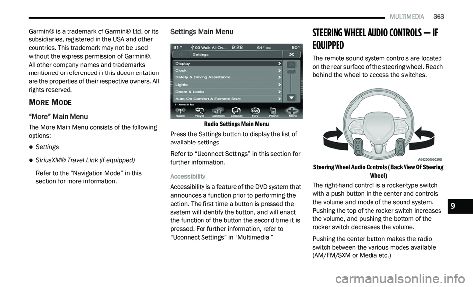
The remote sound system controls are located
on the rear surface of the steering wheel. Reach
behind the wheel to access the switches.
Steering Wheel Audio Controls (Back View Of Steering Wh
eel)
The right-hand control is a rocker-type switch
w i
th a push button in the center and controls
the volume and mode of the sound system.
Pushing the top of the rocker switch increases
the volume, and pushing the bottom of the
rocker switch decreases the volume.
Pushing the center button makes the radio
s w
itch between the various modes available
(AM/FM/SXM or Media etc.)
9
Page 367 of 396
MULTIMEDIA 365
UCONNECT MULTIMEDIA — VIDEO
ENTERTAINMENT SYSTEM (VES)
(IF EQUIPPED)
Your rear seat Video Entertainment System
(VES) is designed to give your family years of
enjoyment. You can play your favorite CDs or
DVDs, listen to audio over the wireless
headphones, or plug and play a variety of
standard video games or audio devices. Please
review this Owner's Manual to become familiar
with its features and operation.
NOTE:
The screen is located in the 2nd row overhead
c o
nsole.
GETTING STARTED
Screen located in the overhead console :
Unfold the overhead LCD screen by pushing
the button on the overhead console behind
the screen.
Overhead Video Screen
With the ignition switch in the ON/RUN or
ACC position, turn the radio on by pushing the
ON/OFF Volume Control knob.
When the Video Screen is open and a DVD is
inserted into the radio, the screen turns on
automatically, the headphone transmitters
turn on and playback begins.
SINGLE VIDEO SCREEN
NOTE:
Typically there are two different ways to operate
t h
e features of the Video Entertainment System
(VES).
The Remote Control
The Touchscreen Radio (if equipped)
PLAY VIDEO GAMES
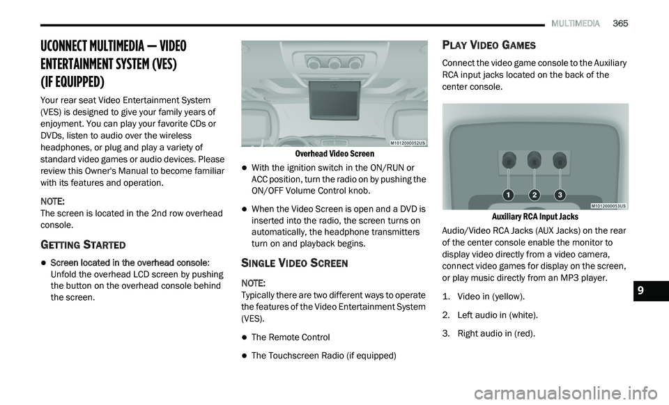
Connect the video game console to the Auxiliary
RCA input jacks located on the back of the
center console.
Auxiliary RCA Input Jacks
Audio/Video RCA Jacks (AUX Jacks) on the rear
o f
the center console enable the monitor to
display video directly from a video camera,
connect video games for display on the screen,
or play music directly from an MP3 player.
1. V ideo in (yellow).
2
. Le ft audio in (white).
3
. R ight audio in (red).
9