DODGE MAGNUM SRT 2007 1.G Owners Manual
Manufacturer: DODGE, Model Year: 2007, Model line: MAGNUM SRT, Model: DODGE MAGNUM SRT 2007 1.GPages: 380, PDF Size: 6.63 MB
Page 141 of 380
turn on in the event of an EBD failure. Immediate repair
of the ABS system is required in the event of an EBD
failure.
The operation of the Brake Warning Light can be checked
by turning the ignition switch from the OFF position to
the ON position. The light should turn on for approxi-
mately two seconds and then turn off. The light will
remain on if the parking brake is applied or if a brake
fault is detected. If the parking brake is not applied and
the light remains on, or if the light does not turn on, have
the light inspected by an authorized dealer.
NOTE:The light will turn on when the ignition switch
in the ON position and the parking brake is applied. This
light shows only that the parking brake is applied. It does
not show the degree of brake application. (See page 219
for more information.)
21. Vehicle Security Alarm (VSA) Indicator Light Ð
If Equipped
The VSA indicator Light flashes rapidly when the VSA is
arming, and slowly when the VSA is armed. (See page 15
for more information.)
22. Tire Pressure Monitoring Telltale Light Ð If
Equipped
Each tire, including the spare (if provided),
should be checked monthly when cold and
inflated to the inflation pressure recom-
mended by the vehicle manufacturer on the
vehicle placard or tire inflation pressure label. (If your
vehicle has tires of a different size than the size
indicated on the vehicle placard or tire inflation pres-
sure label, you should determine the proper tire
inflation pressure for those tires.)
As an added safety feature, your vehicle has been
equipped with a tire pressure monitoring system (TPMS)
that illuminates a low tire pressure telltale when one or
more of your tires are significantly under-inflated. Ac-
cordingly, when the low tire pressure telltale illuminates,
you should stop and check your tires as soon as possible,
and inflate them to the proper pressure. Driving on a
significantly under-inflated tire causes the tire to over-
heat and can lead to tire failure. Under-inflation also
reduces fuel efficiency and tire tread life, and may affect
the vehicle's handling and stopping ability.
140 UNDERSTANDING YOUR INSTRUMENT PANEL
Page 142 of 380
Please note that the TPMS is not a substitute for proper
tire maintenance, and it is the driver 's responsibility to
maintain correct tire pressure, even if under-inflation has
not reached the level to trigger illumination of the TPMS
low tire pressure telltale.
The Tire Pressure Monitoring Telltale Light will illumi-
nate in the instrument cluster, and an audible chime will
be activated when one or more tire pressures is low. The
Tire Pressure Monitoring Telltale Light will flash on and
off for 60 seconds when a system fault is detected. The
flash cycle will repeat every ten minutes or until the fault
condition is removed and reset. (See page 246 for more
information.)CAUTION!
The TPMS has been optimized for the original
equipment tires and wheels. TPMS pressures and
warning have been established for the tire size
equipped on your vehicle. Undesirable system op-
eration or sensor damage may result when using
replacement equipment that is not of the same size,
type, and/or style. After-market wheels can cause
sensor damage. Do not use tire sealant from a can, or
balance beads if your vehicle is equipped with a
TPMS, as damage to the sensors may result.
UNDERSTANDING YOUR INSTRUMENT PANEL 141
4
Page 143 of 380
23. Anti-Lock Brake Light
This light monitors the Anti-Lock Brake System.
The light will turn on when the ignition switch
is turned to the ON position and may stay on for as
long as four seconds.
If the ABS light remains on or turns on while driving,
then the Anti-Lock portion of the brake system is not
functioning and service is required. However, the con-
ventional brake system will continue to operate normally
if the BRAKE warning light is not on.
If the ABS light is on, the brake system should be serviced
as soon as possible to restore the benefits of Anti-Lock
brakes. If the ABS light does not turn on when the
Ignition switch is turned to the ON position, have the
light inspected by an authorized dealer. (See page 219 for
more information.)
24. Low Fuel Indicator Light
This light will turn on and a single chime will
sound when the fuel level drops to 1/8 tank. (See
page 257 for more information.)25. Malfunction Indicator Light
This light is part of an onboard diagnostic
system called OBD. The OBD system monitors
engine and automatic transmission control sys-
tems. The light will turn on when the key is in the ON
position before engine start. If the light does not come
on when turning the key from OFF to ON, have the
condition checked promptly.
Certain conditions such as a loose or missing gas cap,
poor fuel quality, etc. may illuminate the light after
engine start. The vehicle should be serviced if the light
stays on through several of your typical driving cycles. In
most situations, the vehicle will drive normally and will
not require towing.
The Malfunction Indicator Light flashes to alert you to
serious conditions that could lead to immediate loss of
power or severe catalytic converter damage. The vehicle
should be serviced as soon as possible if this occurs. (See
page 292 for more information.)
142 UNDERSTANDING YOUR INSTRUMENT PANEL
Page 144 of 380
ELECTRONIC VEHICLE INFORMATION CENTER
(EVIC)
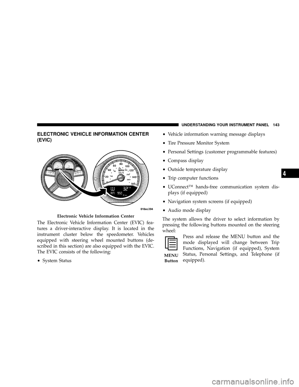
The Electronic Vehicle Information Center (EVIC) fea-
tures a driver-interactive display. It is located in the
instrument cluster below the speedometer. Vehicles
equipped with steering wheel mounted buttons (de-
scribed in this section) are also equipped with the EVIC.
The EVIC consists of the following:
²System Status
²Vehicle information warning message displays
²Tire Pressure Monitor System
²Personal Settings (customer programmable features)
²Compass display
²Outside temperature display
²Trip computer functions
²UConnectŸ hands-free communication system dis-
plays (if equipped)
²Navigation system screens (if equipped)
²Audio mode display
The system allows the driver to select information by
pressing the following buttons mounted on the steering
wheel:
Press and release the MENU button and the
mode displayed will change between Trip
Functions, Navigation (if equipped), System
Status, Personal Settings, and Telephone (if
equipped).
Electronic Vehicle Information Center
MENU
Button
UNDERSTANDING YOUR INSTRUMENT PANEL 143
4
Page 145 of 380
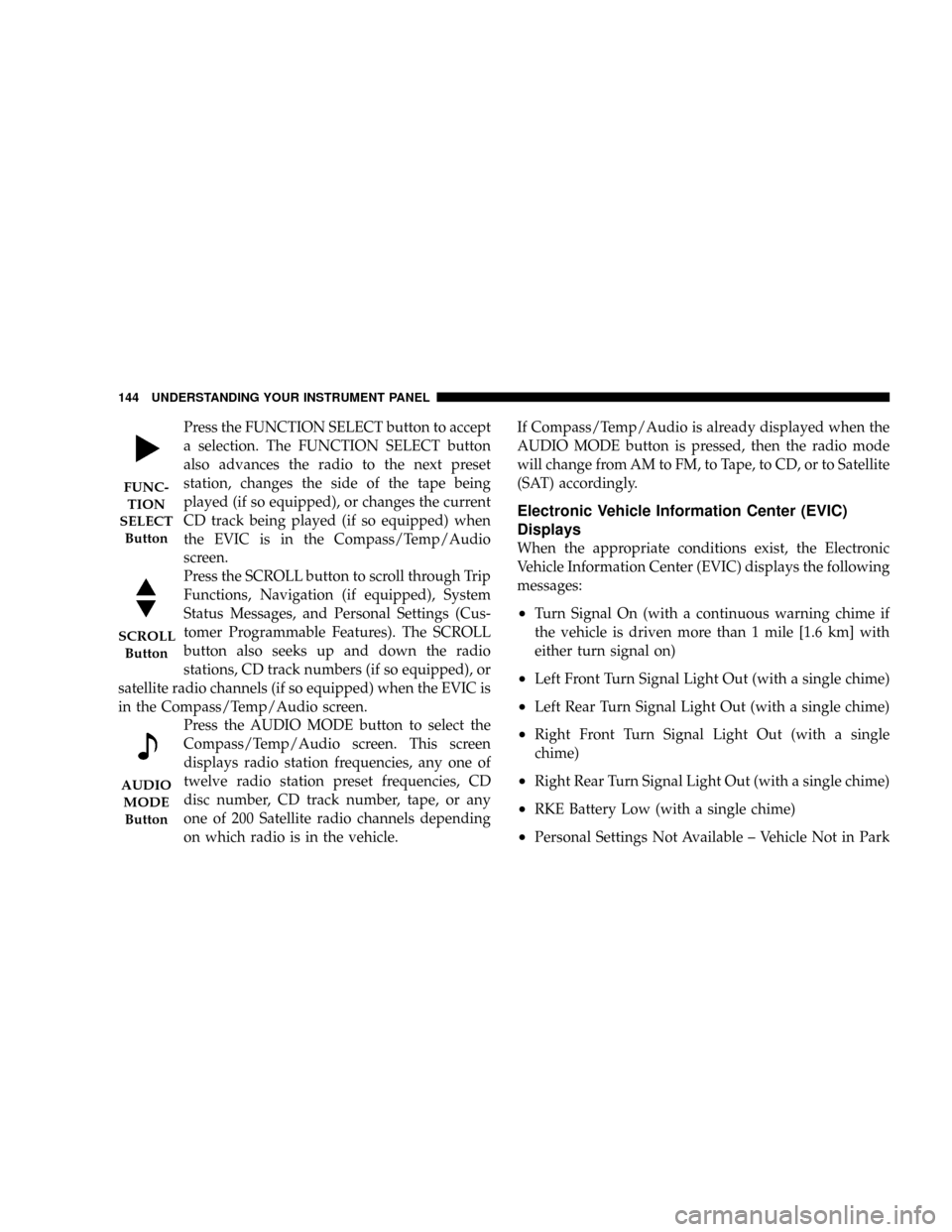
Press the FUNCTION SELECT button to accept
a selection. The FUNCTION SELECT button
also advances the radio to the next preset
station, changes the side of the tape being
played (if so equipped), or changes the current
CD track being played (if so equipped) when
the EVIC is in the Compass/Temp/Audio
screen.
Press the SCROLL button to scroll through Trip
Functions, Navigation (if equipped), System
Status Messages, and Personal Settings (Cus-
tomer Programmable Features). The SCROLL
button also seeks up and down the radio
stations, CD track numbers (if so equipped), or
satellite radio channels (if so equipped) when the EVIC is
in the Compass/Temp/Audio screen.
Press the AUDIO MODE button to select the
Compass/Temp/Audio screen. This screen
displays radio station frequencies, any one of
twelve radio station preset frequencies, CD
disc number, CD track number, tape, or any
one of 200 Satellite radio channels depending
on which radio is in the vehicle.If Compass/Temp/Audio is already displayed when the
AUDIO MODE button is pressed, then the radio mode
will change from AM to FM, to Tape, to CD, or to Satellite
(SAT) accordingly.
Electronic Vehicle Information Center (EVIC)
Displays
When the appropriate conditions exist, the Electronic
Vehicle Information Center (EVIC) displays the following
messages:
²Turn Signal On (with a continuous warning chime if
the vehicle is driven more than 1 mile [1.6 km] with
either turn signal on)
²Left Front Turn Signal Light Out (with a single chime)
²Left Rear Turn Signal Light Out (with a single chime)
²Right Front Turn Signal Light Out (with a single
chime)
²Right Rear Turn Signal Light Out (with a single chime)
²RKE Battery Low (with a single chime)
²Personal Settings Not Available ± Vehicle Not in Park
FUNC-
TION
SELECT
Button
SCROLL
Button
AUDIO
MODE
Button
144 UNDERSTANDING YOUR INSTRUMENT PANEL
Page 146 of 380
![DODGE MAGNUM SRT 2007 1.G Owners Manual ²Left/Right Front Door Ajar (one or more, with a single
chime if speed is above 1 mph [1.6 km])
²Left/Right Rear Door Ajar (one or more, with a single
chime if speed is above 1 mph [1.6 km])
²Door( DODGE MAGNUM SRT 2007 1.G Owners Manual ²Left/Right Front Door Ajar (one or more, with a single
chime if speed is above 1 mph [1.6 km])
²Left/Right Rear Door Ajar (one or more, with a single
chime if speed is above 1 mph [1.6 km])
²Door(](/img/12/5658/w960_5658-145.png)
²Left/Right Front Door Ajar (one or more, with a single
chime if speed is above 1 mph [1.6 km])
²Left/Right Rear Door Ajar (one or more, with a single
chime if speed is above 1 mph [1.6 km])
²Door(s) Ajar (with a single chime if vehicle is in
motion)
²Trunk Ajar (with a single chime)
²Low Washer Fluid (with a single chime)
²Channel 1, 2, OR 3 Transmit
²Channel 1, 2, OR 3 Training
²Channel 1, 2, OR 3 Trained
²Clearing Channels
²Channels Cleared
²Channels Defaulted
²Did Not Train
²Left Front Low Pressure (with a single chime). Refer to
ªStarting And Operating, Tire Sectionº
²Left Rear Low Pressure (with a single chime). Refer to
ªStarting And Operating, Tire Sectionº
²Right Front Low Pressure (with a single chime). Refer
to ªStarting And Operating, Tire Sectionº
²Right Rear Low Pressure (with a single chime). Refer
to ªStarting And Operating, Tire Sectionº
²Check TPM System (with a single chime). Refer to
ªStarting And Operating, Tire Sectionº
²Check Gascap (refer to ªAdding Fuelº in Section 5 of
this manual for more details)
²Upshift
Trip Functions
Press and release the MENU button until one of the
following Trip Functions displays in the EVIC:
²Average Fuel Economy
²Distance To Empty
²Trip A
²Trip B
UNDERSTANDING YOUR INSTRUMENT PANEL 145
4
Page 147 of 380
²Elapsed Time
²Display Units of Measure in
Press the SCROLL button to cycle through all the Trip
Computer functions.
The Trip Functions mode displays the following:
²Average Fuel Economy
Shows the average fuel economy since the last reset.
When the fuel economy is reset, the display will read
ªRESETº or show dashes for two seconds. Then, the
history information will be erased, and the averaging will
continue from the last fuel average reading before the
reset.
²Distance To Empty (DTE)
Shows the estimated distance that can be traveled with
the fuel remaining in the tank. This estimated distance is
determined by a weighted average of the instantaneous
and average fuel economy, according to the current fuel
tank level. DTE cannot be reset through the FUNCTION
SELECT button.
NOTE:Significant changes in driving style or vehicle
loading will greatly affect the actual drivable distance of
the vehicle, regardless of the DTE displayed value.
²When the DTE value is less than 30 miles (48 km)
estimated driving distance, the DTE display will
change to a text display of9LOW FUEL.9This display
will continue until the vehicle runs out of fuel. Adding
a significant amount of fuel to the vehicle will turn off
the9LOW FUEL9text and a new DTE value will
display.
²Trip A
Shows the total distance traveled for trip A since the last
reset.
²Trip B
Shows the total distance traveled for trip B since the last
reset.
²Elapsed Time
Shows the total elapsed time of travel since the last reset
when the ignition switch is in the ACC position. Elapsed
time will increment when the ignition switch is in the ON
or START position.
146 UNDERSTANDING YOUR INSTRUMENT PANEL
Page 148 of 380
²Display Units of Measure in:
To make your selection, press and release the FUNC-
TION SELECT button until ªUSº or ªMETRICº appears.
To Reset The Display
Reset will only occur while a resettable function is being
displayed. Press and release the FUNCTION SELECT
button once to clear the resettable function being dis-
played. To reset all resettable functions, press and release
the FUNCTION SELECT button a second time within 3
seconds of resetting the currently displayed function
(>Reset ALL will display during this 3 second window).
Compass Display
The compass readings indicate the direction
the vehicle is facing. Press and release the
compass button to display one of eight com-
pass readings and the outside temperature.
Automatic Compass Calibration
This compass is self-calibrating, which eliminates the
need to set the compass manually. When the vehicle is
new, the compass may appear erratic and the EVIC willdisplay ªCALº until the compass is calibrated. You may
also calibrate the compass by completing one or more
360É turns (in an area free from large metal or metallic
objects) until the ªCALº message displayed in the EVIC
turns off. The compass will now function normally.
Manual Compass Calibration
If the compass appears erratic and the ªCALº message
does not appear in the EVIC display, you must put the
compass into the Calibration Mode manually as follows:
1. Turn on the ignition switch.
2. Press and hold the compass button for approximately
2 seconds.
3. Press the SCROLL button until ªCalibrate Compassº
displays in the EVIC.
4. Press and release the FUNCTION SELECT button to
start the calibration. The message ªCALº will display in
the EVIC.
5. Complete one or more 360É turns (in an area free from
large metal or metallic objects) until the ªCALº message
turns off. The compass will now function normally.
COM-
PASS
Button
UNDERSTANDING YOUR INSTRUMENT PANEL 147
4
Page 149 of 380
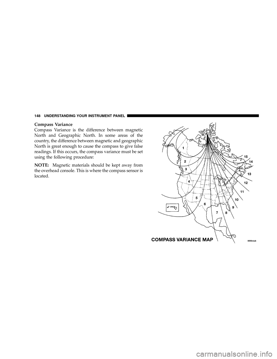
Compass Variance
Compass Variance is the difference between magnetic
North and Geographic North. In some areas of the
country, the difference between magnetic and geographic
North is great enough to cause the compass to give false
readings. If this occurs, the compass variance must be set
using the following procedure:
NOTE:Magnetic materials should be kept away from
the overhead console. This is where the compass sensor is
located.
148 UNDERSTANDING YOUR INSTRUMENT PANEL
Page 150 of 380
1. Turn the ignition switch ON.
2. Press and hold the compass button for approximately
2 seconds.
3. Press the SCROLL button until ªCompass Varianceº
message and the last variance zone number displays in
the EVIC.
4. Press and release FUNCTION SELECT button until
the proper variance zone is selected according to the
map.
5. Press and release the compass button to exit.
Telephone Ð If Equipped
Press and release the MENU button until ªTelephoneº
displays in the EVIC.
When the appropriate conditions exist, the EVIC pro-
vides the following telephone information:
²Phone status: idle, voice mail, roaming, battery
strength, and signal strength in increments of 20
percent.
²Call status: Incoming call, connecting, connected, air
time in minutes and seconds, call ended, call failed,
roaming, and no phone connection.
²UConnect Active.
²Caller ID phone number display.
When the appropriate conditions exist, and if supported
by the cell phone, the EVIC will display the following
telephone symbols:
The EVIC displays this symbol to indicate the
signal strength of the UConnectŸ phone. The
number of horizontal bars increases as the
strength of the UConnectŸ phone signal in-
creases.
The EVIC displays this symbol to indicate an
incoming call.
Signal
Strength
Incom-
ing Call
UNDERSTANDING YOUR INSTRUMENT PANEL 149
4