DODGE MAGNUM SRT 2007 1.G Owners Manual
Manufacturer: DODGE, Model Year: 2007, Model line: MAGNUM SRT, Model: DODGE MAGNUM SRT 2007 1.GPages: 380, PDF Size: 6.63 MB
Page 121 of 380
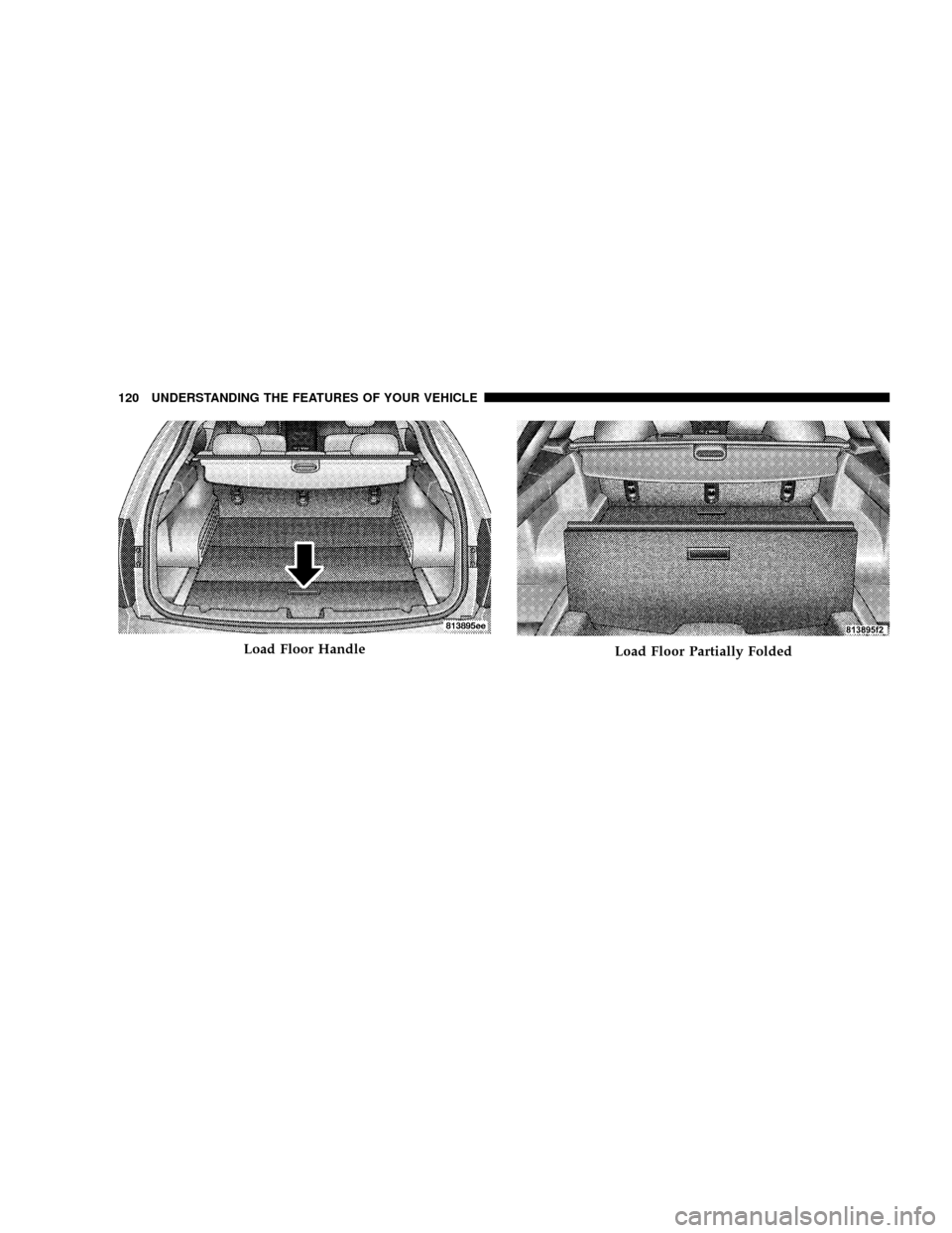
Load Floor HandleLoad Floor Partially Folded
120 UNDERSTANDING THE FEATURES OF YOUR VEHICLE
Page 122 of 380

Rollaway Tonneau Cover Ð If Equipped
The removable rollaway tonneau cover mounts in the
cargo area behind the top of the rear seats.
Load Floor Fully Folded
UNDERSTANDING THE FEATURES OF YOUR VEHICLE 121
3
Page 123 of 380
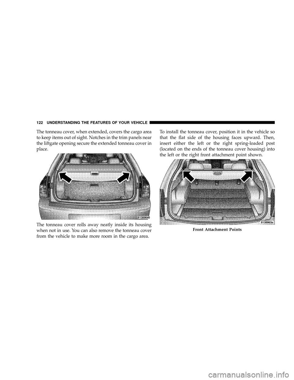
The tonneau cover, when extended, covers the cargo area
to keep items out of sight. Notches in the trim panels near
the liftgate opening secure the extended tonneau cover in
place.
The tonneau cover rolls away neatly inside its housing
when not in use. You can also remove the tonneau cover
from the vehicle to make more room in the cargo area.To install the tonneau cover, position it in the vehicle so
that the flat side of the housing faces upward. Then,
insert either the left or the right spring-loaded post
(located on the ends of the tonneau cover housing) into
the left or the right front attachment point shown.
Front Attachment Points
122 UNDERSTANDING THE FEATURES OF YOUR VEHICLE
Page 124 of 380
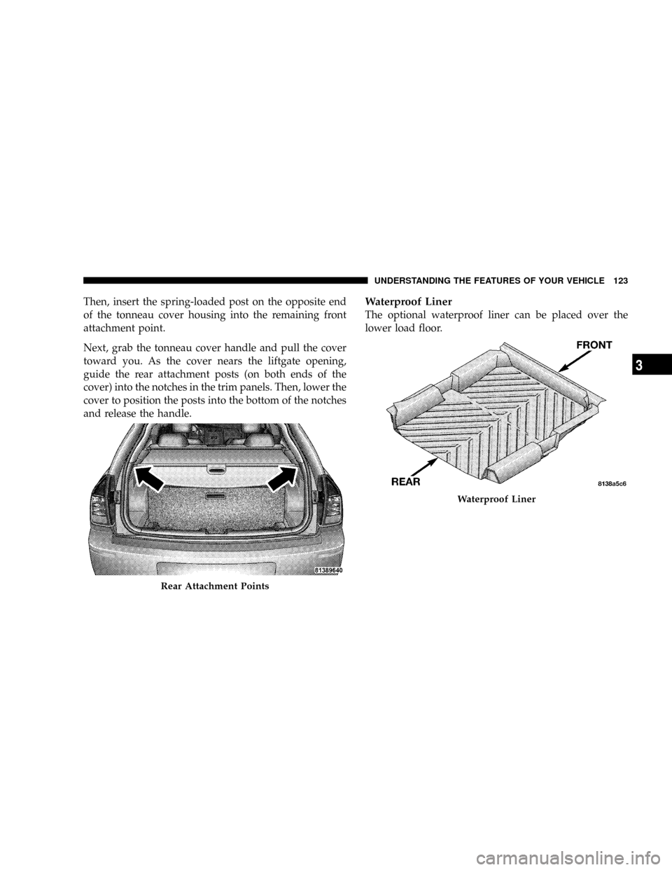
Then, insert the spring-loaded post on the opposite end
of the tonneau cover housing into the remaining front
attachment point.
Next, grab the tonneau cover handle and pull the cover
toward you. As the cover nears the liftgate opening,
guide the rear attachment posts (on both ends of the
cover) into the notches in the trim panels. Then, lower the
cover to position the posts into the bottom of the notches
and release the handle.Waterproof Liner
The optional waterproof liner can be placed over the
lower load floor.
Rear Attachment Points
Waterproof Liner
UNDERSTANDING THE FEATURES OF YOUR VEHICLE 123
3
Page 125 of 380
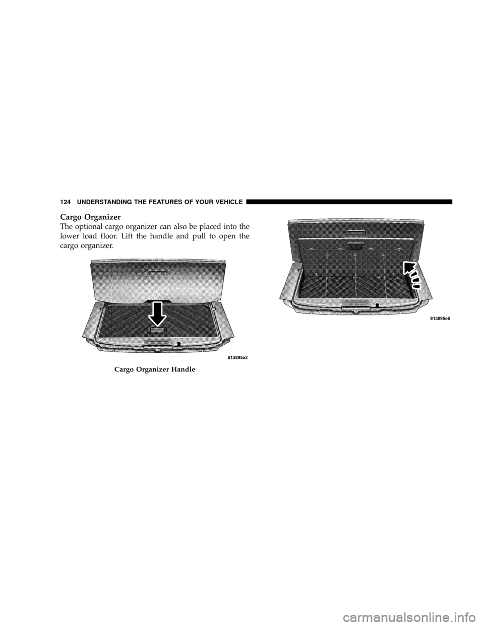
Cargo Organizer
The optional cargo organizer can also be placed into the
lower load floor. Lift the handle and pull to open the
cargo organizer.
Cargo Organizer Handle
124 UNDERSTANDING THE FEATURES OF YOUR VEHICLE
Page 126 of 380
Cargo Tie-Down Hooks
The tie-downs located on cargo area floor and on the rear
trim panels should be used to safely secure loads when
vehicle is moving.
WARNING!
²Cargo tie-down hooks are not safe anchors for a
child seat tether strap. In a sudden stop or colli-
sion, a hook could pull loose and allow the child
seat to come loose. A child could be badly injured.
Use only the anchors provided for child seat
tethers.
²The weight and position of cargo and passengers
can change the vehicle center of gravity and
vehicle handling. To avoid loss of control result-
ing in personal injury, follow these guidelines for
loading your vehicle:
²Always place cargo evenly on the cargo floor. Put
heavier objects as low and as far forward as possible.
²Place as much cargo as possible in front of the rear
axle. Too much weight or improperly placed weight
over or behind the rear axle can cause the rear of the
vehicle to sway.
²Do not pile luggage or cargo higher than the top of the
seatback. This could impair visibility or become a
dangerous projectile in a sudden stop or collision.
WARNING!
To help protect against personal injury, passengers
should not be seated in the rear cargo area. The rear
cargo space is intended for load carrying purposes
only, not for passengers, who should sit in seats and
use seat belts.
UNDERSTANDING THE FEATURES OF YOUR VEHICLE 125
3
Page 127 of 380
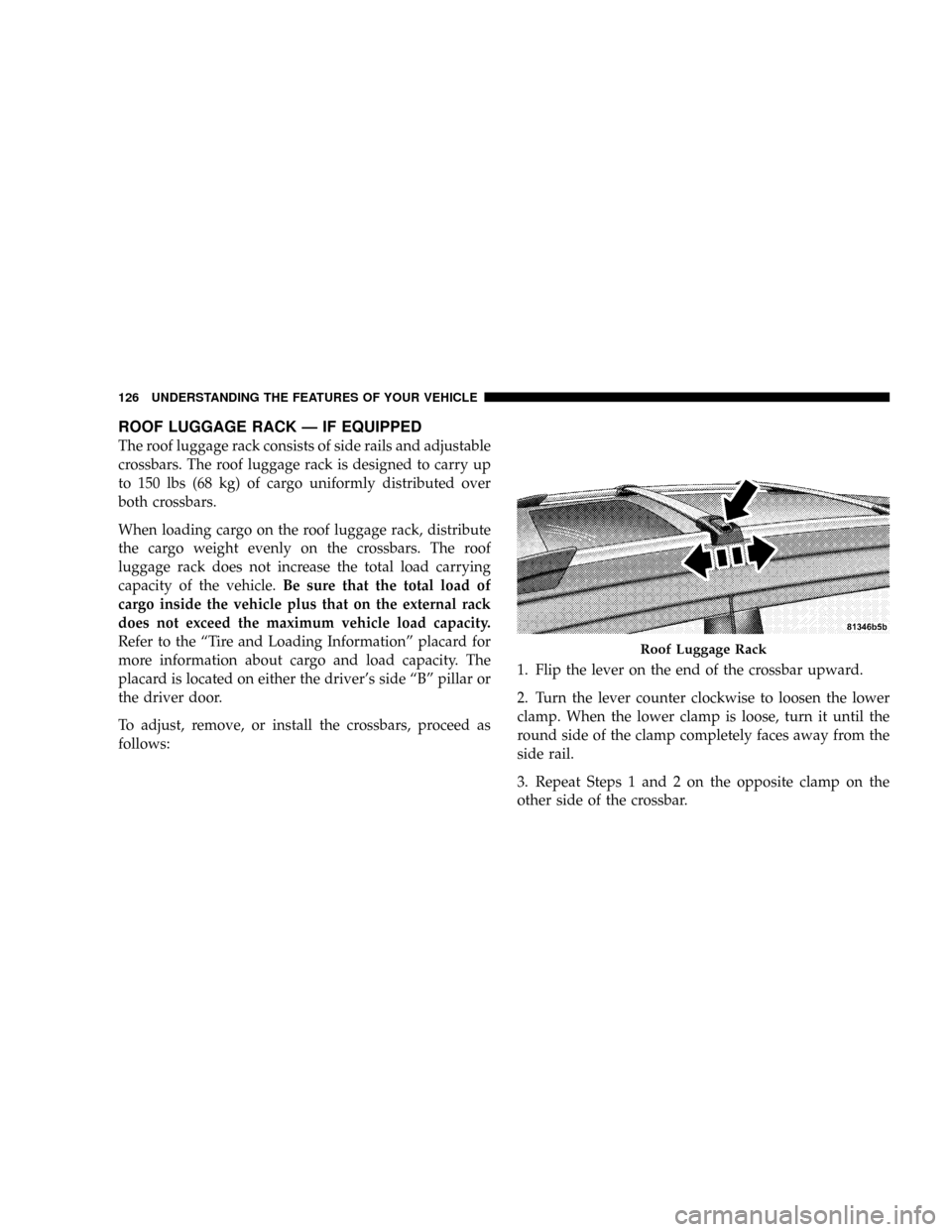
ROOF LUGGAGE RACK Ð IF EQUIPPED
The roof luggage rack consists of side rails and adjustable
crossbars. The roof luggage rack is designed to carry up
to 150 lbs (68 kg) of cargo uniformly distributed over
both crossbars.
When loading cargo on the roof luggage rack, distribute
the cargo weight evenly on the crossbars. The roof
luggage rack does not increase the total load carrying
capacity of the vehicle.Be sure that the total load of
cargo inside the vehicle plus that on the external rack
does not exceed the maximum vehicle load capacity.
Refer to the ªTire and Loading Informationº placard for
more information about cargo and load capacity. The
placard is located on either the driver's side ªBº pillar or
the driver door.
To adjust, remove, or install the crossbars, proceed as
follows:1. Flip the lever on the end of the crossbar upward.
2. Turn the lever counter clockwise to loosen the lower
clamp. When the lower clamp is loose, turn it until the
round side of the clamp completely faces away from the
side rail.
3. Repeat Steps 1 and 2 on the opposite clamp on the
other side of the crossbar.
Roof Luggage Rack
126 UNDERSTANDING THE FEATURES OF YOUR VEHICLE
Page 128 of 380
4. Pick up the crossbar and move it to the desired
location. Do not place the crossbar directly over the
sunroof glass (if equipped).
5. Turn the lower clamp until the round side of the clamp
completely faces the side rail.
6. Turn the lever clockwise to tighten the lower clamp to
the side rail. When tight, flip the lever downward.
7. Repeat Steps 5 and 6 on the opposite clamp on the
other side of the crossbar.
8. Attempt to move the crossbar to ensure that it is
locked in position.
NOTE:To reduce the amount of wind noise when the
crossbars are not in use, remove both crossbars from the
side rails and place them inside the vehicle.
CAUTION!
²To avoid damage to the roof rack and vehicle, do
not exceed the maximum roof rack load capacity
of 150 lbs (68 kg). Always distribute heavy loads
as evenly as possible and secure the load appro-
priately.
²Long loads, which extend over the windshield,
such as wood panels or surfboards, or loads with
large frontal area should be secured to both the
front and rear of the vehicle.
²Travel at reduced speeds and turn corners care-
fully when carrying large or heavy loads on the
roof rack. Wind forces, due to natural causes or
nearby truck traffic, can add sudden upward
loads. This is especially true on large flat loads
and may result in damage to the cargo or your
vehicle.
²Do not use the pop-up feature of the sliding /
pop-up roof when positioning or placing luggage
above it, to prevent damage to the sliding / pop-up
roof panel.
UNDERSTANDING THE FEATURES OF YOUR VEHICLE 127
3
Page 129 of 380
WARNING!
Cargo must be securely tied before driving your
vehicle. Improperly secured loads can fly off the
vehicle, particularly at high speeds, resulting in
personal injury or property damage. Follow the Roof
Rack Cautions when carrying cargo on your roof
rack.
LOAD LEVELING SYSTEM
The automatic load leveling system will provide a level-
riding vehicle under most passenger and cargo loading
conditions.
A hydraulic pump contained within the shock absorbers
raises the rear of the vehicle to the correct height. It takes
approximately 1 mile (1.6 km) of driving for the leveling
to complete depending on road surface conditions.
If the leveled vehicle is not moved for approximately 15
hours, the leveling system will bleed itself down. The
vehicle must be driven to reset the system.
128 UNDERSTANDING THE FEATURES OF YOUR VEHICLE
Page 130 of 380
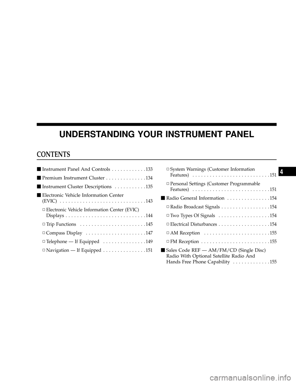
UNDERSTANDING YOUR INSTRUMENT PANEL
CONTENTS
mInstrument Panel And Controls............133
mPremium Instrument Cluster..............134
mInstrument Cluster Descriptions...........135
mElectronic Vehicle Information Center
(EVIC)
..............................143
NElectronic Vehicle Information Center (EVIC)
Displays............................144
NTrip Functions.......................145
NCompass Display.....................147
NTelephone Ð If Equipped...............149
NNavigation Ð If Equipped...............151NSystem Warnings (Customer Information
Features)...........................151
NPersonal Settings (Customer Programmable
Features)...........................151mRadio General Information...............154
NRadio Broadcast Signals.................154
NTwo Types Of Signals..................154
NElectrical Disturbances..................154
NAM Reception.......................155
NFM Reception........................155
mSales Code REF Ð AM/FM/CD (Single Disc)
Radio With Optional Satellite Radio And
Hands Free Phone Capability
.............155
4