Drain plug DODGE NEON 1999 Service Repair Manual
[x] Cancel search | Manufacturer: DODGE, Model Year: 1999, Model line: NEON, Model: DODGE NEON 1999Pages: 1200, PDF Size: 35.29 MB
Page 198 of 1200
SELECTION AND ADDITIVES
The use of aluminum cylinder heads, intake mani-
folds DOHC, and water pumps requires special corro-
sion protection. MopartAntifreeze or the equivalent
is recommended for best engine cooling without cor-
rosion. When mixed only to a freeze point of -37ÉC
(-35ÉF) to -59ÉC (-50ÉF). If it looses color or becomes
contaminated, drain, flush, and replace with fresh
properly mixed solution.
COOLING SYSTEM PRESSURE CAP
The cooling system is equipped with a pressure cap
that releases built up pressure, maintaining a range
of 97-124 kPa (14-18 psi).
The cooling system will operate at higher than
atmospheric pressure. The higher pressure raises the
coolant boiling point thus, allowing increased radia-
tor cooling capacity.
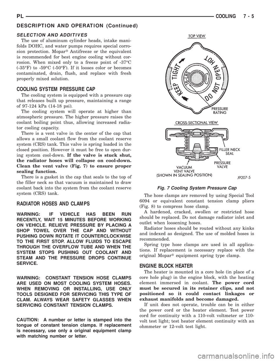
There is a vent valve in the center of the cap that
allows a small coolant flow from the coolant reserve
system (CRS) tank. This valve is spring loaded in the
closed position. However it must be free to open dur-
ing system cool-down.If the valve is stuck shut,
the radiator hoses will collapse on cool-down.
Clean the vent valve (Fig. 7) to ensure proper
sealing function.
There is a gasket in the cap that seals to the top of
the filler neck so that vacuum is maintained to draw
coolant back into the system from the coolant reserve
system (CRS) tank.
RADIATOR HOSES AND CLAMPS
WARNING: IF VEHICLE HAS BEEN RUN
RECENTLY, WAIT 15 MINUTES BEFORE WORKING
ON VEHICLE. RELIEVE PRESSURE BY PLACING A
SHOP TOWEL OVER THE CAP AND WITHOUT
PUSHING DOWN ROTATE IT COUNTERCLOCKWISE
TO THE FIRST STOP. ALLOW FLUIDS TO ESCAPE
THROUGH THE OVERFLOW TUBE AND WHEN THE
SYSTEM STOPS PUSHING OUT COOLANT AND
STEAM AND THE PRESSURE DROPS CONTINUE
SERVICE.
WARNING: CONSTANT TENSION HOSE CLAMPS
ARE USED ON MOST COOLING SYSTEM HOSES.
WHEN REMOVING OR INSTALLING, USE ONLY
TOOLS DESIGNED FOR SERVICING THIS TYPE OF
CLAM. ALWAYS WEAR SAFETY GLASSES WHEN
SERVICING CONSTANT TENSION CLAMPS.
CAUTION: A number or letter is stamped into the
tongue of constant tension clamps. If replacement
is necessary, use only a original equipment clamp
with matching number or letter.The hose clamps are removed by using Special Tool
6094 or equivalent constant tension clamp pliers
(Fig. 8) to compress hose clamp.
A hardened, cracked, swollen or restricted hose
should be replaced. Do not damage radiator inlet and
outlet when loosening hoses.
Radiator hoses should be routed without any kinks
and indexed as designed. The use of molded hoses is
recommended.
Spring type hose clamps are used in all applica-
tions. If replacement is necessary replace with the
original Mopartequipment spring type clamp.
ENGINE BLOCK HEATER
The heater is mounted in a core hole (in place of a
core hole plug) in the engine block, with the heating
element immersed in coolant.The power cord
must be secured in its retainer clips, and not
positioned so it could contact linkages or
exhaust manifolds and become damaged.
If unit does not operate, trouble can be in either
the power cord or the heater element. Test power
cord for continuity with a 110-volt voltmeter or 110-
volt test light; test heater element continuity with an
ohmmeter or 12-volt test light.
Fig. 7 Cooling System Pressure Cap
PLCOOLING 7 - 5
DESCRIPTION AND OPERATION (Continued)
Page 212 of 1200
RADIATOR
REMOVAL
WARNING: DO NOT REMOVE THE CYLINDER
BLOCK PLUG OR THE RADIATOR DRAINCOCK
WITH THE SYSTEM HOT AND UNDER PRESSURE
BECAUSE SERIOUS BURNS FROM COOLANT CAN
OCCUR.
(1) Disconnect negative battery cable from battery.
(2) Drain cooling system. Refer to Cooling System
Draining in this section.
(3) Remove engine air inlet duct.
(4) Remove upper radiator hose from the radiator.
(5) Disconnect and cap automatic transmission
hoses, if equipped.
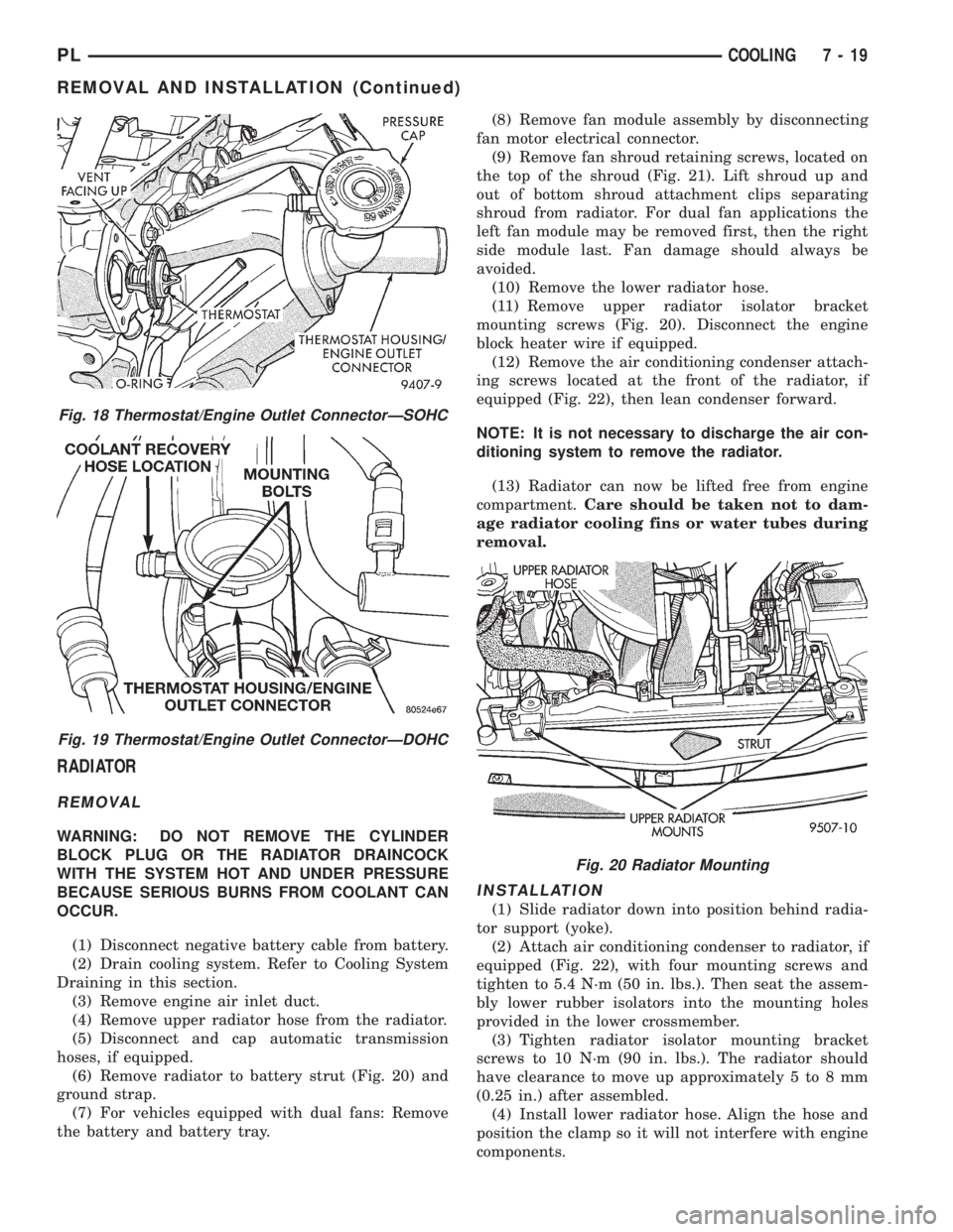
(6) Remove radiator to battery strut (Fig. 20) and
ground strap.
(7) For vehicles equipped with dual fans: Remove
the battery and battery tray.(8) Remove fan module assembly by disconnecting
fan motor electrical connector.
(9) Remove fan shroud retaining screws, located on
the top of the shroud (Fig. 21). Lift shroud up and
out of bottom shroud attachment clips separating
shroud from radiator. For dual fan applications the
left fan module may be removed first, then the right
side module last. Fan damage should always be
avoided.
(10) Remove the lower radiator hose.
(11) Remove upper radiator isolator bracket
mounting screws (Fig. 20). Disconnect the engine
block heater wire if equipped.
(12) Remove the air conditioning condenser attach-
ing screws located at the front of the radiator, if
equipped (Fig. 22), then lean condenser forward.
NOTE: It is not necessary to discharge the air con-
ditioning system to remove the radiator.
(13) Radiator can now be lifted free from engine
compartment.Care should be taken not to dam-
age radiator cooling fins or water tubes during
removal.
INSTALLATION
(1) Slide radiator down into position behind radia-
tor support (yoke).
(2) Attach air conditioning condenser to radiator, if
equipped (Fig. 22), with four mounting screws and
tighten to 5.4 N´m (50 in. lbs.). Then seat the assem-
bly lower rubber isolators into the mounting holes
provided in the lower crossmember.
(3) Tighten radiator isolator mounting bracket
screws to 10 N´m (90 in. lbs.). The radiator should
have clearance to move up approximately 5 to 8 mm
(0.25 in.) after assembled.
(4) Install lower radiator hose. Align the hose and
position the clamp so it will not interfere with engine
components.
Fig. 18 Thermostat/Engine Outlet ConnectorÐSOHC
Fig. 19 Thermostat/Engine Outlet ConnectorÐDOHC
Fig. 20 Radiator Mounting
PLCOOLING 7 - 19
REMOVAL AND INSTALLATION (Continued)
Page 214 of 1200
must be replaced withonlythe recommended part
for adequate strength, performance and safety.
(1) To remove fan from motor shaft, bench support
the motor and motor shaft, while removing the fan
retaining clip, so that the shaft and motor will not be
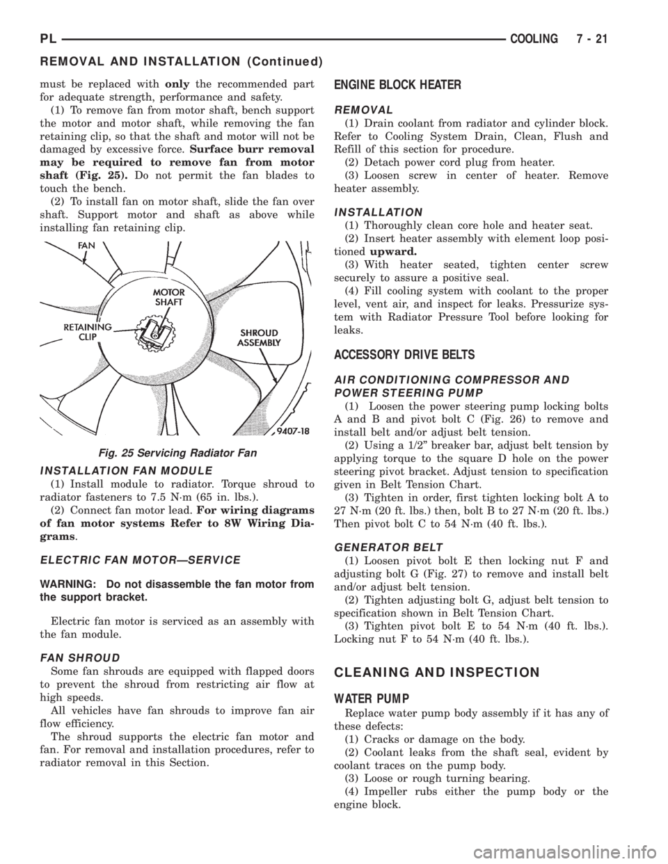
damaged by excessive force.Surface burr removal
may be required to remove fan from motor
shaft (Fig. 25).Do not permit the fan blades to
touch the bench.
(2) To install fan on motor shaft, slide the fan over
shaft. Support motor and shaft as above while
installing fan retaining clip.
INSTALLATION FAN MODULE
(1) Install module to radiator. Torque shroud to
radiator fasteners to 7.5 N´m (65 in. lbs.).
(2) Connect fan motor lead.For wiring diagrams
of fan motor systems Refer to 8W Wiring Dia-
grams.
ELECTRIC FAN MOTORÐSERVICE
WARNING: Do not disassemble the fan motor from
the support bracket.
Electric fan motor is serviced as an assembly with
the fan module.
FAN SHROUD
Some fan shrouds are equipped with flapped doors
to prevent the shroud from restricting air flow at
high speeds.
All vehicles have fan shrouds to improve fan air
flow efficiency.
The shroud supports the electric fan motor and
fan. For removal and installation procedures, refer to
radiator removal in this Section.
ENGINE BLOCK HEATER
REMOVAL
(1) Drain coolant from radiator and cylinder block.
Refer to Cooling System Drain, Clean, Flush and
Refill of this section for procedure.
(2) Detach power cord plug from heater.
(3) Loosen screw in center of heater. Remove
heater assembly.
INSTALLATION
(1) Thoroughly clean core hole and heater seat.
(2) Insert heater assembly with element loop posi-
tionedupward.
(3) With heater seated, tighten center screw
securely to assure a positive seal.
(4) Fill cooling system with coolant to the proper
level, vent air, and inspect for leaks. Pressurize sys-
tem with Radiator Pressure Tool before looking for
leaks.
ACCESSORY DRIVE BELTS
AIR CONDITIONING COMPRESSOR AND
POWER STEERING PUMP
(1) Loosen the power steering pump locking bolts
A and B and pivot bolt C (Fig. 26) to remove and
install belt and/or adjust belt tension.
(2) Using a 1/2º breaker bar, adjust belt tension by
applying torque to the square D hole on the power
steering pivot bracket. Adjust tension to specification
given in Belt Tension Chart.
(3) Tighten in order, first tighten locking bolt A to
27 N´m (20 ft. lbs.) then, bolt B to 27 N´m (20 ft. lbs.)
Then pivot bolt C to 54 N´m (40 ft. lbs.).
GENERATOR BELT
(1) Loosen pivot bolt E then locking nut F and
adjusting bolt G (Fig. 27) to remove and install belt
and/or adjust belt tension.
(2) Tighten adjusting bolt G, adjust belt tension to
specification shown in Belt Tension Chart.
(3) Tighten pivot bolt E to 54 N´m (40 ft. lbs.).
Locking nut F to 54 N´m (40 ft. lbs.).
CLEANING AND INSPECTION
WATER PUMP
Replace water pump body assembly if it has any of
these defects:
(1) Cracks or damage on the body.
(2) Coolant leaks from the shaft seal, evident by
coolant traces on the pump body.
(3) Loose or rough turning bearing.
(4) Impeller rubs either the pump body or the
engine block.
Fig. 25 Servicing Radiator Fan
PLCOOLING 7 - 21
REMOVAL AND INSTALLATION (Continued)
Page 216 of 1200
Cooling System). Run engine with radiator cap
installed until upper radiator hose is hot. Stop
engine and drain water from system. If water is
dirty, fill, run and drain system again until water
runs clear.
RADIATOR FLUSHING
Drain cooling system and remove radiator hoses
from engine. Install suitable flushing gun in radiator
lower hose. Fill radiator with clean water and turn
on air in short blasts.
CAUTION: Internal radiator pressure must not
exceed 138 kPa (20 psi) as damage to radiator may
result. Continue this procedure until water runs
clear.
ENGINE FLUSHING
Drain radiator (see:Cooling System Draining)
and remove hoses from radiator. Remove engine ther-
mostat and reinstall thermostat housing. A gasket
may be needed to seal the housing to cylinder head
because the seal is part of thermostat. Install suit-
able flushing gun to thermostat housing hose. Turn
on water, and when engine is filled, turn on air, but
no higher than 138 kPa (20 psi) in short blasts. Allowengine to fill between blasts of air. Continue this pro-
cedure until water runs clean. Install thermostat and
fill cooling system. Refer to (Cooling System Refill-
ing) for procedure.
REVERSE FLUSHING
Reverse flushing of the cooling system is the forc-
ing of water through the cooling system, using air
pressure in a direction opposite to that of the normal
flow of water. This is only necessary with dirty sys-
tems and evidence of partial plugging.
CHEMICAL CLEANING
One type of corrosion encountered with aluminum
cylinder heads is aluminum hydroxide deposits. Cor-
rosion products are carried to the radiator and depos-
ited when cooled off. They appear as dark grey when
wet and white when dry. This corrosion can be
removed with a two part cleaner (oxalic acid and
neutralizer) available in auto parts outlets. Follow
manufacturers directions for use.
ADJUSTMENTS
PROPER BELT TENSION
Satisfactory performance of the belt driven accesso-
ries depends on belt condition and proper belt ten-
sion. Refer to Accessory Drive Belt Inspection in this
section. There are two belt tensioning methods given
in order of preference:
²Belt tension gauge method.
²Torque equivalent method.
The belt tension gauge method usually requires the
vehicle to be raised on a hoist and the splash shield
removed.
TORQUE EQUIVALENT METHOD
Adjustable accessory brackets provided with a 13
mm (1/2 in.) square hole for a torque wrench can use
an equivalent torque value for belt adjustment.
Equivalent torque values for adjusting these acces-
sory drive belts are specified in the Belt Tension
Chart.
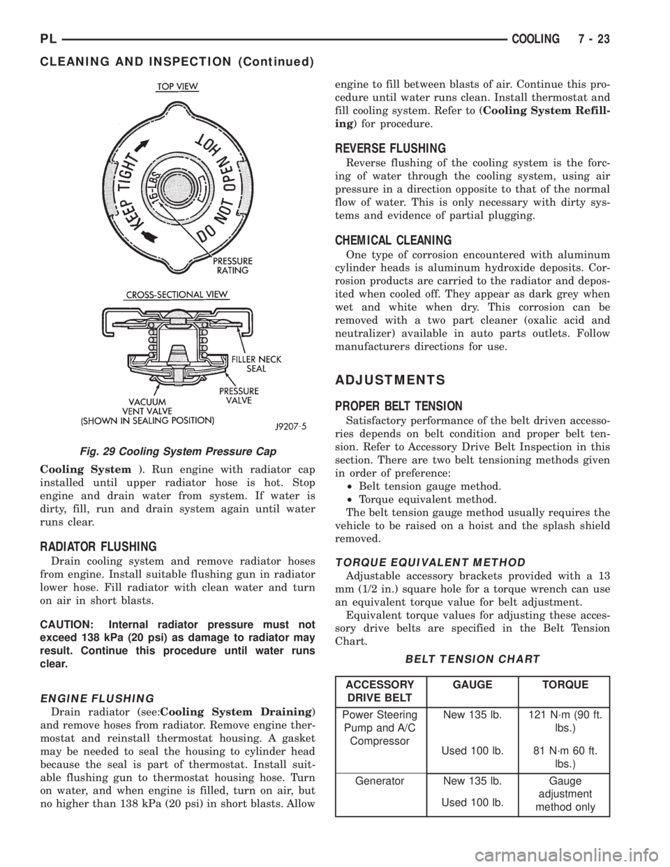
Fig. 29 Cooling System Pressure Cap
BELT TENSION CHART
ACCESSORY
DRIVE BELTGAUGE TORQUE
Power Steering
Pump and A/C
CompressorNew 135 lb. 121 N´m (90 ft.
lbs.)
Used 100 lb. 81 N´m 60 ft.
lbs.)
Generator New 135 lb. Gauge
adjustment
method only Used 100 lb.
PLCOOLING 7 - 23
CLEANING AND INSPECTION (Continued)
Page 322 of 1200
REMOVAL AND INSTALLATION
WASHER NOZZLE
REMOVAL
(1) Disconnect washer fluid hose at the nozzle.
(2) Using a needle nose pliers, squeeze together
the locking tabs on the nozzle (Fig. 1).
(3) Remove nozzle.
INSTALLATION
(1) Place the nozzle in position and push down-
ward till locking tabs are securely snapped into posi-
tion.
(2) Connect the washer hose and ensure that the
hose is not kinked.
WASHER RESERVOIR
REMOVAL
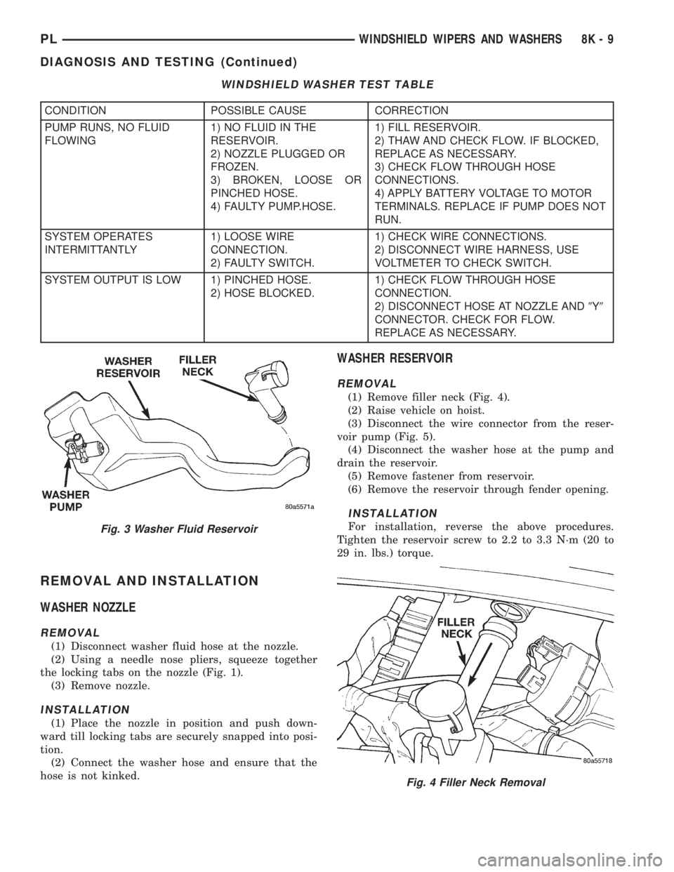
(1) Remove filler neck (Fig. 4).
(2) Raise vehicle on hoist.
(3) Disconnect the wire connector from the reser-
voir pump (Fig. 5).
(4) Disconnect the washer hose at the pump and
drain the reservoir.
(5) Remove fastener from reservoir.
(6) Remove the reservoir through fender opening.
INSTALLATION
For installation, reverse the above procedures.
Tighten the reservoir screw to 2.2 to 3.3 N´m (20 to
29 in. lbs.) torque.
WINDSHIELD WASHER TEST TABLE
CONDITION POSSIBLE CAUSE CORRECTION
PUMP RUNS, NO FLUID
FLOWING1) NO FLUID IN THE
RESERVOIR.
2) NOZZLE PLUGGED OR
FROZEN.
3) BROKEN, LOOSE OR
PINCHED HOSE.
4) FAULTY PUMP.HOSE.1) FILL RESERVOIR.
2) THAW AND CHECK FLOW. IF BLOCKED,
REPLACE AS NECESSARY.
3) CHECK FLOW THROUGH HOSE
CONNECTIONS.
4) APPLY BATTERY VOLTAGE TO MOTOR
TERMINALS. REPLACE IF PUMP DOES NOT
RUN.
SYSTEM OPERATES
INTERMITTANTLY1) LOOSE WIRE
CONNECTION.
2) FAULTY SWITCH.1) CHECK WIRE CONNECTIONS.
2) DISCONNECT WIRE HARNESS, USE
VOLTMETER TO CHECK SWITCH.
SYSTEM OUTPUT IS LOW 1) PINCHED HOSE.
2) HOSE BLOCKED.1) CHECK FLOW THROUGH HOSE
CONNECTION.
2) DISCONNECT HOSE AT NOZZLE AND9Y9
CONNECTOR. CHECK FOR FLOW.
REPLACE AS NECESSARY.
Fig. 3 Washer Fluid Reservoir
Fig. 4 Filler Neck Removal
PLWINDSHIELD WIPERS AND WASHERS 8K - 9
DIAGNOSIS AND TESTING (Continued)
Page 718 of 1200
(2) Remove negative battery cable.
(3) Place a shop towel around the spark plugs
when removing them from the engine. This will catch
any fluid that may possibly be in the cylinder under
pressure.
(4) With all spark plugs removed, rotate engine
crankshaft using a breaker bar and socket.
(5) Identify the fluid in the cylinder(s) (i.e., cool-
ant, fuel, oil or other).
(6) Make sure all fluid has been removed from the
cylinders. Inspect engine for damage (i.e., Connecting
Rods, Pistons, Valves etc.)
(7) Repair engine or components as necessary to
prevent this problem from occurring again.
CAUTION: Squirt approximately 1 teaspoon of oil
into cylinders, rotate engine to lubricate the cylin-
der walls to prevent damage on restart.
(8) Install new spark plugs.
(9) Drain engine oil and remove oil filter.
(10) Fill engine with specified amount of approved
oil and install new oil filter.
(11) Connect negative battery cable.
(12) Start engine and check for any leaks.
CHECKING ENGINE OIL LEVEL
The best time to check engine oil level is after it
has sat overnight, or if the engine has been running,
allow the engine to be shut off for at least 5 minutes
before checking oil level.
Checking the oil while the vehicle is on level
ground will improve the accuracy of the oil level
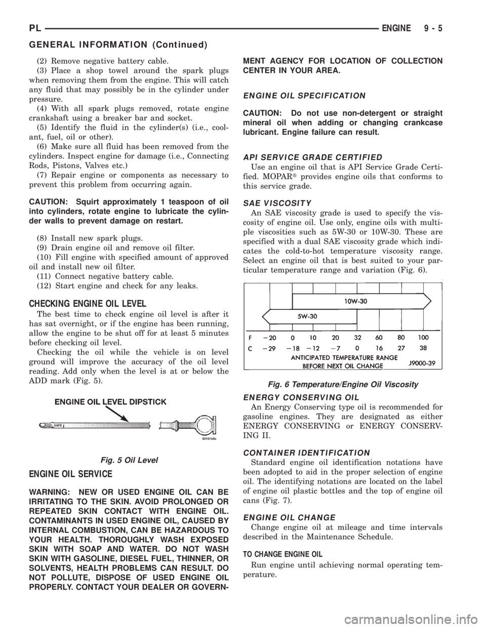
reading. Add only when the level is at or below the
ADD mark (Fig. 5).
ENGINE OIL SERVICE
WARNING: NEW OR USED ENGINE OIL CAN BE
IRRITATING TO THE SKIN. AVOID PROLONGED OR
REPEATED SKIN CONTACT WITH ENGINE OIL.
CONTAMINANTS IN USED ENGINE OIL, CAUSED BY
INTERNAL COMBUSTION, CAN BE HAZARDOUS TO
YOUR HEALTH. THOROUGHLY WASH EXPOSED
SKIN WITH SOAP AND WATER. DO NOT WASH
SKIN WITH GASOLINE, DIESEL FUEL, THINNER, OR
SOLVENTS, HEALTH PROBLEMS CAN RESULT. DO
NOT POLLUTE, DISPOSE OF USED ENGINE OIL
PROPERLY. CONTACT YOUR DEALER OR GOVERN-MENT AGENCY FOR LOCATION OF COLLECTION
CENTER IN YOUR AREA.
ENGINE OIL SPECIFICATION
CAUTION: Do not use non-detergent or straight
mineral oil when adding or changing crankcase
lubricant. Engine failure can result.
API SERVICE GRADE CERTIFIED
Use an engine oil that is API Service Grade Certi-
fied. MOPARtprovides engine oils that conforms to
this service grade.
SAE VISCOSITY
An SAE viscosity grade is used to specify the vis-
cosity of engine oil. Use only, engine oils with multi-
ple viscosities such as 5W-30 or 10W-30. These are
specified with a dual SAE viscosity grade which indi-
cates the cold-to-hot temperature viscosity range.
Select an engine oil that is best suited to your par-
ticular temperature range and variation (Fig. 6).
ENERGY CONSERVING OIL
An Energy Conserving type oil is recommended for
gasoline engines. They are designated as either
ENERGY CONSERVING or ENERGY CONSERV-
ING II.
CONTAINER IDENTIFICATION
Standard engine oil identification notations have
been adopted to aid in the proper selection of engine
oil. The identifying notations are located on the label
of engine oil plastic bottles and the top of engine oil
cans (Fig. 7).
ENGINE OIL CHANGE
Change engine oil at mileage and time intervals
described in the Maintenance Schedule.
TO CHANGE ENGINE OIL
Run engine until achieving normal operating tem-
perature.
Fig. 5 Oil Level
Fig. 6 Temperature/Engine Oil Viscosity
PLENGINE 9 - 5
GENERAL INFORMATION (Continued)
Page 719 of 1200
(1) Position the vehicle on a level surface and turn
engine off.
(2) Hoist and support vehicle on safety stands.
Refer to Hoisting and Jacking Recommendations.(3) Remove oil fill cap.
(4) Place a suitable drain pan under crankcase
drain.
(5) Remove drain plug from crankcase and allow
oil to drain into pan. Inspect drain plug threads for
stretching or other damage. Replace drain plug and
gasket if damaged.
(6) Install drain plug in crankcase.
(7) Lower vehicle and fill crankcase with specified
type and amount of engine oil described in this sec-
tion.
(8) Install oil fill cap.
(9) Start engine and inspect for leaks.
(10) Stop engine and inspect oil level.
Fig. 7 Engine Oil Container Standard Notations
9 - 6 ENGINEPL
GENERAL INFORMATION (Continued)
Page 732 of 1200
(3) Remove the power hop damper bracket, if nec-
essary.
(4) Reverse removal procedure for installation.
Tighten all bolts and nuts to 54 N´m (40 ft. lbs.)
STRUCTURAL COLLARÐ2.0L
REMOVAL
(1) Raise vehicle on hoist.
NOTE: To remove transaxle dust cover, the front
bending strut must be removed.
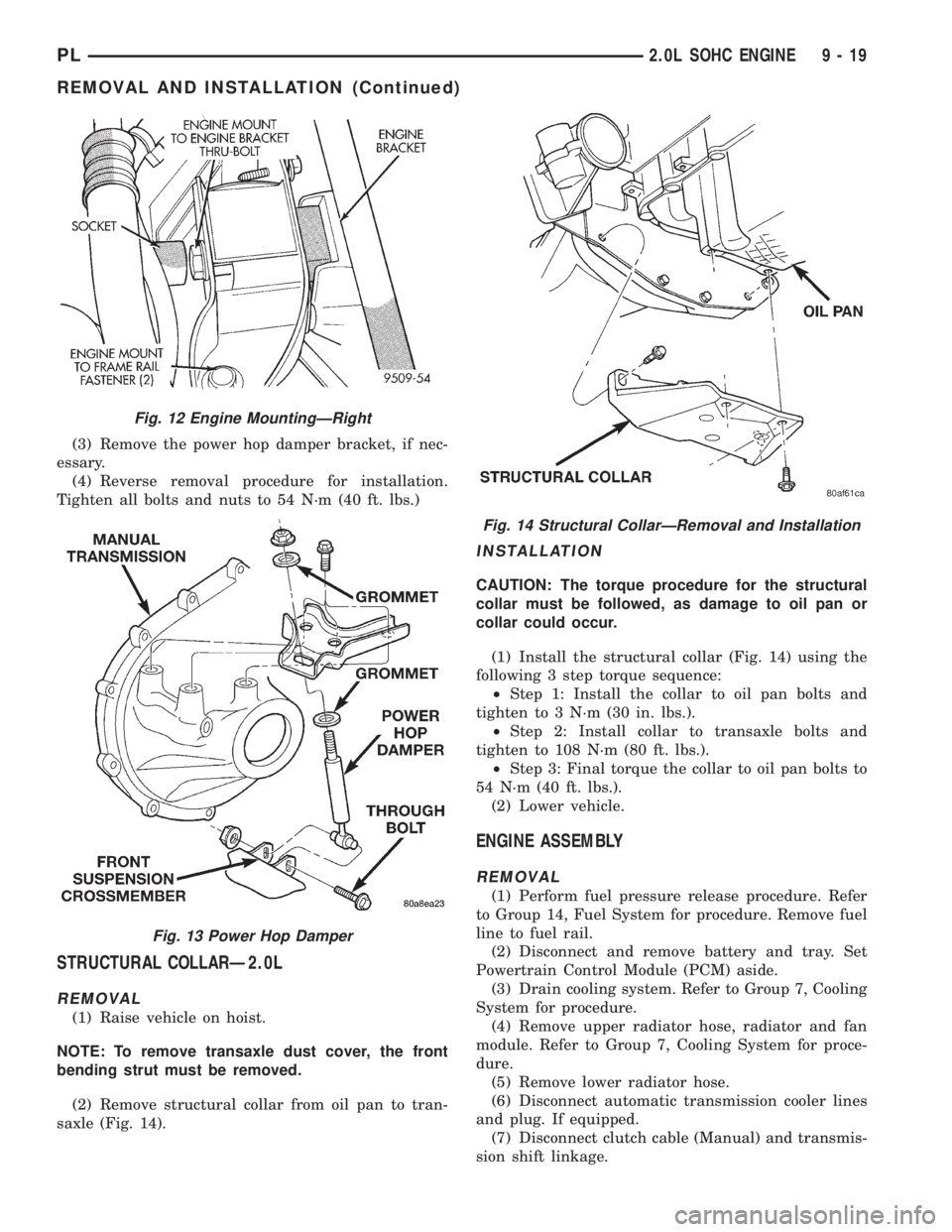
(2) Remove structural collar from oil pan to tran-
saxle (Fig. 14).
INSTALLATION
CAUTION: The torque procedure for the structural
collar must be followed, as damage to oil pan or
collar could occur.
(1) Install the structural collar (Fig. 14) using the
following 3 step torque sequence:
²Step 1: Install the collar to oil pan bolts and
tighten to 3 N´m (30 in. lbs.).
²Step 2: Install collar to transaxle bolts and
tighten to 108 N´m (80 ft. lbs.).
²Step 3: Final torque the collar to oil pan bolts to
54 N´m (40 ft. lbs.).
(2) Lower vehicle.
ENGINE ASSEMBLY
REMOVAL
(1) Perform fuel pressure release procedure. Refer
to Group 14, Fuel System for procedure. Remove fuel
line to fuel rail.
(2) Disconnect and remove battery and tray. Set
Powertrain Control Module (PCM) aside.
(3) Drain cooling system. Refer to Group 7, Cooling
System for procedure.
(4) Remove upper radiator hose, radiator and fan
module. Refer to Group 7, Cooling System for proce-
dure.
(5) Remove lower radiator hose.
(6) Disconnect automatic transmission cooler lines
and plug. If equipped.
(7) Disconnect clutch cable (Manual) and transmis-
sion shift linkage.
Fig. 12 Engine MountingÐRight
Fig. 13 Power Hop Damper
Fig. 14 Structural CollarÐRemoval and Installation
PL2.0L SOHC ENGINE 9 - 19
REMOVAL AND INSTALLATION (Continued)
Page 767 of 1200
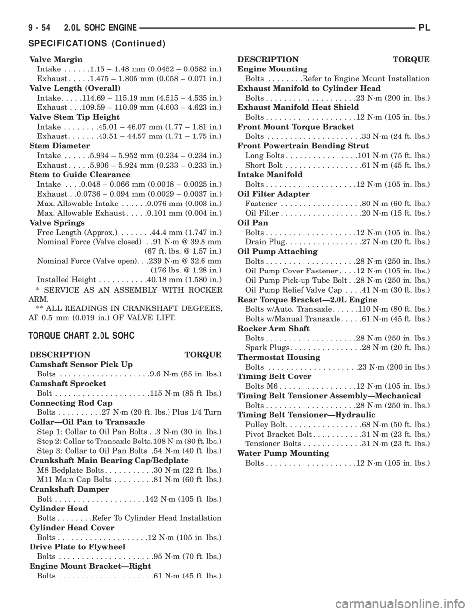
Valve Margin
Intake......1.15 ± 1.48 mm (0.0452 ± 0.0582 in.)
Exhaust.....1.475 ± 1.805 mm (0.058 ± 0.071 in.)
Valve Length (Overall)
Intake.....114.69 ± 115.19 mm (4.515 ± 4.535 in.)
Exhaust . . .109.59 ± 110.09 mm (4.603 ± 4.623 in.)
Valve Stem Tip Height
Intake........45.01 ± 46.07 mm (1.77 ± 1.81 in.)
Exhaust.......43.51 ± 44.57 mm (1.71 ± 1.75 in.)
Stem Diameter
Intake......5.934 ± 5.952 mm (0.234 ± 0.234 in.)
Exhaust.....5.906 ± 5.924 mm (0.233 ± 0.233 in.)
Stem to Guide Clearance
Intake. . . .0.048 ± 0.066 mm (0.0018 ± 0.0025 in.)
Exhaust . .0.0736 ± 0.094 mm (0.0029 ± 0.0037 in.)
Max. Allowable Intake......0.076 mm (0.003 in.)
Max. Allowable Exhaust.....0.101 mm (0.004 in.)
Valve Springs
Free Length (Approx.).......44.4 mm (1.747 in.)
Nominal Force (Valve closed) . .91 N´m @ 39.8 mm
(67 ft. lbs. @ 1.57 in.)
Nominal Force (Valve open). . .239 N´m @ 32.6 mm
(176 lbs. @ 1.28 in.)
Installed Height...........40.18 mm (1.580 in.)
* SERVICE AS AN ASSEMBLY WITH ROCKER
ARM.
** ALL READINGS IN CRANKSHAFT DEGREES,
AT 0.5 mm (0.019 in.) OF VALVE LIFT.
TORQUE CHART 2.0L SOHC
DESCRIPTION TORQUE
Camshaft Sensor Pick Up
Bolts....................9.6 N´m (85 in. lbs.)
Camshaft Sprocket
Bolt.....................115N´m(85ft.lbs.)
Connecting Rod Cap
Bolts..........27N´m(20ft.lbs.) Plus 1/4 Turn
CollarÐOil Pan to Transaxle
Step 1: Collar to Oil Pan Bolts . .3 N´m (30 in. lbs.)
Step 2: Collar to Transaxle Bolts.108 N´m (80 ft. lbs.)
Step 3: Collar to Oil Pan Bolts .54 N´m (40 ft. lbs.)
Crankshaft Main Bearing Cap/Bedplate
M8 Bedplate Bolts...........30N´m(22ft.lbs.)
M11 Main Cap Bolts.........81N´m(60ft.lbs.)
Crankshaft Damper
Bolt....................142 N´m (105 ft. lbs.)
Cylinder Head
Bolts........Refer To Cylinder Head Installation
Cylinder Head Cover
Bolts....................12N´m(105 in. lbs.)
Drive Plate to Flywheel
Bolts.....................95N´m(70ft.lbs.)
Engine Mount BracketÐRight
Bolts.....................61N´m(45ft.lbs.)DESCRIPTION TORQUE
Engine Mounting
Bolts........Refer to Engine Mount Installation
Exhaust Manifold to Cylinder Head
Bolts....................23N´m(200 in. lbs.)
Exhaust Manifold Heat Shield
Bolts....................12N´m(105 in. lbs.)
Front Mount Torque Bracket
Bolts.....................33N´m(24ft.lbs.)
Front Powertrain Bending Strut
Long Bolts................101 N´m (75 ft. lbs.)
Short Bolt.................61N´m(45ft.lbs.)
Intake Manifold
Bolts....................12N´m(105 in. lbs.)
Oil Filter Adapter
Fastener..................80N´m(60ft.lbs.)
Oil Filter..................20N´m(15ft.lbs.)
Oil Pan
Bolts....................12N´m(105 in. lbs.)
Drain Plug.................27N´m(20ft.lbs.)
Oil Pump Attaching
Bolts....................28N´m(250 in. lbs.)
Oil Pump Cover Fastener. . . .12 N´m (105 in. lbs.)
Oil Pump Pick-up Tube Bolt . .28 N´m (250 in. lbs.)
Oil Pump Relief Valve Cap. . . .41 N´m (30 ft. lbs.)
Rear Torque BracketÐ2.0L Engine
Bolts w/Auto. Transaxle......110N´m(80ft.lbs.)
Bolts w/Manual Transaxle.....61N´m(45ft.lbs.)
Rocker Arm Shaft
Bolts....................28N´m(250 in. lbs.)
Spark Plugs................28N´m(20ft.lbs.)
Thermostat Housing
Bolts....................23N´m(200 in lbs.)
Timing Belt Cover
Bolts M6.................12N´m(105 in. lbs.)
Timing Belt Tensioner AssemblyÐMechanical
Bolts....................28N´m(250 in. lbs.)
Timing Belt TensionerÐHydraulic
Pulley Bolt.................68N´m(50ft.lbs.)
Pivot Bracket Bolt...........31N´m(23ft.lbs.)
Tensioner Bolts.............31N´m(23ft.lbs.)
Water Pump Mounting
Bolts....................12N´m(105 in. lbs.)
9 - 54 2.0L SOHC ENGINEPL
SPECIFICATIONS (Continued)
Page 778 of 1200
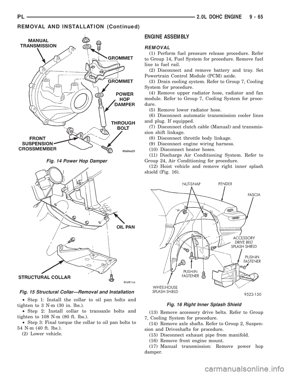
²Step 1: Install the collar to oil pan bolts and
tighten to 3 N´m (30 in. lbs.).
²Step 2: Install collar to transaxle bolts and
tighten to 108 N´m (80 ft. lbs.).
²Step 3: Final torque the collar to oil pan bolts to
54 N´m (40 ft. lbs.).
(2) Lower vehicle.
ENGINE ASSEMBLY
REMOVAL
(1) Perform fuel pressure release procedure. Refer
to Group 14, Fuel System for procedure. Remove fuel
line to fuel rail.
(2) Disconnect and remove battery and tray. Set
Powertrain Control Module (PCM) aside.
(3) Drain cooling system. Refer to Group 7, Cooling
System for procedure.
(4) Remove upper radiator hose, radiator and fan
module. Refer to Group 7, Cooling System for proce-
dure.
(5) Remove lower radiator hose.
(6) Disconnect automatic transmission cooler lines
and plug. If equipped.
(7) Disconnect clutch cable (Manual) and transmis-
sion shift linkage.
(8) Disconnect throttle body linkage.
(9) Disconnect engine wiring harness.
(10) Disconnect heater hoses.
(11) Discharge Air Conditioning System. Refer to
Group 24, Air Conditioning for procedure.
(12) Hoist vehicle and remove right inner splash
shield (Fig. 16).
(13) Remove accessory drive belts. Refer to Group
7, Cooling System for procedure.
(14) Remove axle shafts. Refer to Group 2, Suspen-
sion and Driveshafts for procedure.
(15) Disconnect exhaust pipe from manifold.
(16) Remove front engine mount.
(17) Manual transmission: Remove power hop
damper.
Fig. 14 Power Hop Damper
Fig. 15 Structural CollarÐRemoval and Installation
Fig. 16 Right Inner Splash Shield
PL2.0L DOHC ENGINE 9 - 65
REMOVAL AND INSTALLATION (Continued)