washer fluid DODGE NEON 1999 Service Repair Manual
[x] Cancel search | Manufacturer: DODGE, Model Year: 1999, Model line: NEON, Model: DODGE NEON 1999Pages: 1200, PDF Size: 35.29 MB
Page 4 of 1200
MAINTENANCE SCHEDULES
INDEX
page page
GENERAL INFORMATION
INTRODUCTION......................... 3
SCHEDULE ± A.......................... 3SCHEDULE ± B.......................... 4
UNSCHEDULED INSPECTION............... 3
GENERAL INFORMATION
INTRODUCTION
Service and maintenance procedures for compo-
nents and systems listed in Schedule ± A or B can be
found by using the Group Tab Locator index at the
front of this manual. If it is not clear which group
contains the information needed, refer to the index at
the back of this manual.
There are two maintenance schedules that show
proper service based on the conditions that the vehi-
cle is subjected to. Use the schedule that best
describes these conditions.
Schedule ±A, lists maintenance recommended for
vehicles used for general transportation.
Schedule ±B, lists maintenance recommended for
vehicles used under the following conditions:
²Frequent short trip driving less than 5 miles (8
km)
²Frequent driving in dusty conditions
²Frequent trailer towing
²Extensive idling
²More than 50% of your driving is at sustained
high speeds during hot weather, above 90ÉF (32ÉC)
Where time and mileage are listed, follow the
interval that occurs first.
EMISSION CONTROL SYSTEM MAINTENANCE
The scheduled emission maintenance listed inbold
typeon the Maintenance Schedules, must be done at
the mileage specified to assure the continued proper
functioning of the emission control system. These,
and all other maintenance services included in this
manual, should be done to provide the best vehicle
performance and reliability. More frequent mainte-
nance may be needed for vehicles in severe operating
conditions such as dusty areas and very short trip
driving.
UNSCHEDULED INSPECTION
At Each Stop For Fuel
²Check engine oil level, add as required.
²Check windshield washer solvent and add if
required.
Once A Month
²Check tire pressure and look for unusual wear
or damage.
²Inspect battery, clean, and tighten terminals as
required.
²Check fluid levels of coolant reservoir, power
steering and automatic transmission and add as
required.
²Check all lights and all other electrical items for
correct operation.
At Each Oil Change
²Inspect exhaust system.
²Inspect brake hoses.
²Inspect the CV joints and front suspension com-
ponents.
²Rotate the tires at each oil change interval
shown on Schedule ± A (7,500 miles) or every other
interval shown on schedule ± B (6,000 miles).
²Check coolant level, hoses and clamps.
²Check the manual transaxle fluid level.
²If the mileage is less than 7,500 miles (12 000
km) yearly, replace the engine oil filter at each oil
change.
SCHEDULE ± A
7,500 Miles (12 000 km) or at 6 months
²Change engine oil.
15,000 Miles (24 000 km) or at 12 months
²Change engine oil.
²Replace engine oil filter.
²Adjust drive belt tension.
22,500 Miles (36 000 km) or at 18 months
²Change engine oil.
²Inspect the front brake pads and rear brake lin-
ings.
30,000 Miles (48 000 km) or at 24 months
²Change engine oil.
²Replace engine oil filter.
²Lubricate front suspension ball joints.
²Adjust drive belt tension.
PLLUBRICATION AND MAINTENANCE 0 - 3
Page 53 of 1200
a unique bolt and nut assembly at each end. The lat-
eral arm to rear crossmember attaching bolts are
longer than the lateral arm to knuckle attaching
bolts. Each lateral arm to knuckle attaching bolt and
nut assembly uses 2 flat washers. Each lateral arm
to rear crossmember attaching bolt uses 1 flat
washer and 1 adjustment cam to provide a means for
rear wheel Toe adjustment. The tension strut assem-
bly attaches to a bracket on the frame rail and to the
bottom of the knuckle.
Lateral arms, tension struts and knuckles are nor-
mally replaced only when the part has been damaged
or when the vehicle has been involved in an accident.
If a suspension part has been damaged, be sure to
check the underbody dimensions of the car. If under-
body dimensions of the vehicle are not correct, the
frame must be straightened before replacement sus-
pension components are installed.
DIAGNOSIS AND TESTING
STRUT INSPECTION (ON VEHICLE)
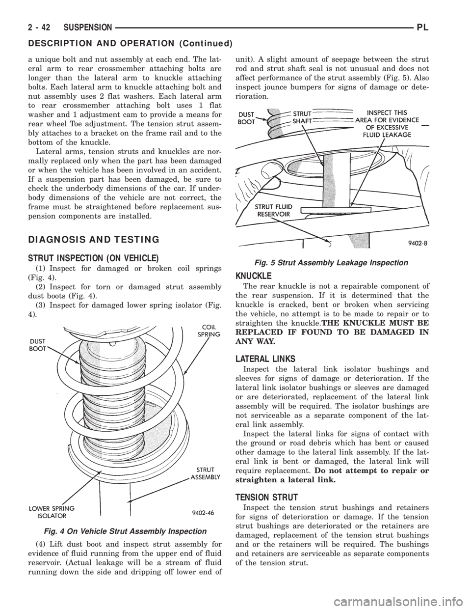
(1) Inspect for damaged or broken coil springs
(Fig. 4).
(2) Inspect for torn or damaged strut assembly
dust boots (Fig. 4).
(3) Inspect for damaged lower spring isolator (Fig.
4).
(4) Lift dust boot and inspect strut assembly for
evidence of fluid running from the upper end of fluid
reservoir. (Actual leakage will be a stream of fluid
running down the side and dripping off lower end ofunit). A slight amount of seepage between the strut
rod and strut shaft seal is not unusual and does not
affect performance of the strut assembly (Fig. 5). Also
inspect jounce bumpers for signs of damage or dete-
rioration.
KNUCKLE
The rear knuckle is not a repairable component of
the rear suspension. If it is determined that the
knuckle is cracked, bent or broken when servicing
the vehicle, no attempt is to be made to repair or to
straighten the knuckle.THE KNUCKLE MUST BE
REPLACED IF FOUND TO BE DAMAGED IN
ANY WAY.
LATERAL LINKS
Inspect the lateral link isolator bushings and
sleeves for signs of damage or deterioration. If the
lateral link isolator bushings or sleeves are damaged
or are deteriorated, replacement of the lateral link
assembly will be required. The isolator bushings are
not serviceable as a separate component of the lat-
eral link assembly.
Inspect the lateral links for signs of contact with
the ground or road debris which has bent or caused
other damage to the lateral link assembly. If the lat-
eral link is bent or damaged, the lateral link will
require replacement.Do not attempt to repair or
straighten a lateral link.
TENSION STRUT
Inspect the tension strut bushings and retainers
for signs of deterioration or damage. If the tension
strut bushings are deteriorated or the retainers are
damaged, replacement of the tension strut bushings
and or the retainers will be required. The bushings
and retainers are serviceable as separate components
of the tension strut.
Fig. 4 On Vehicle Strut Assembly Inspection
Fig. 5 Strut Assembly Leakage Inspection
2 - 42 SUSPENSIONPL
DESCRIPTION AND OPERATION (Continued)
Page 71 of 1200
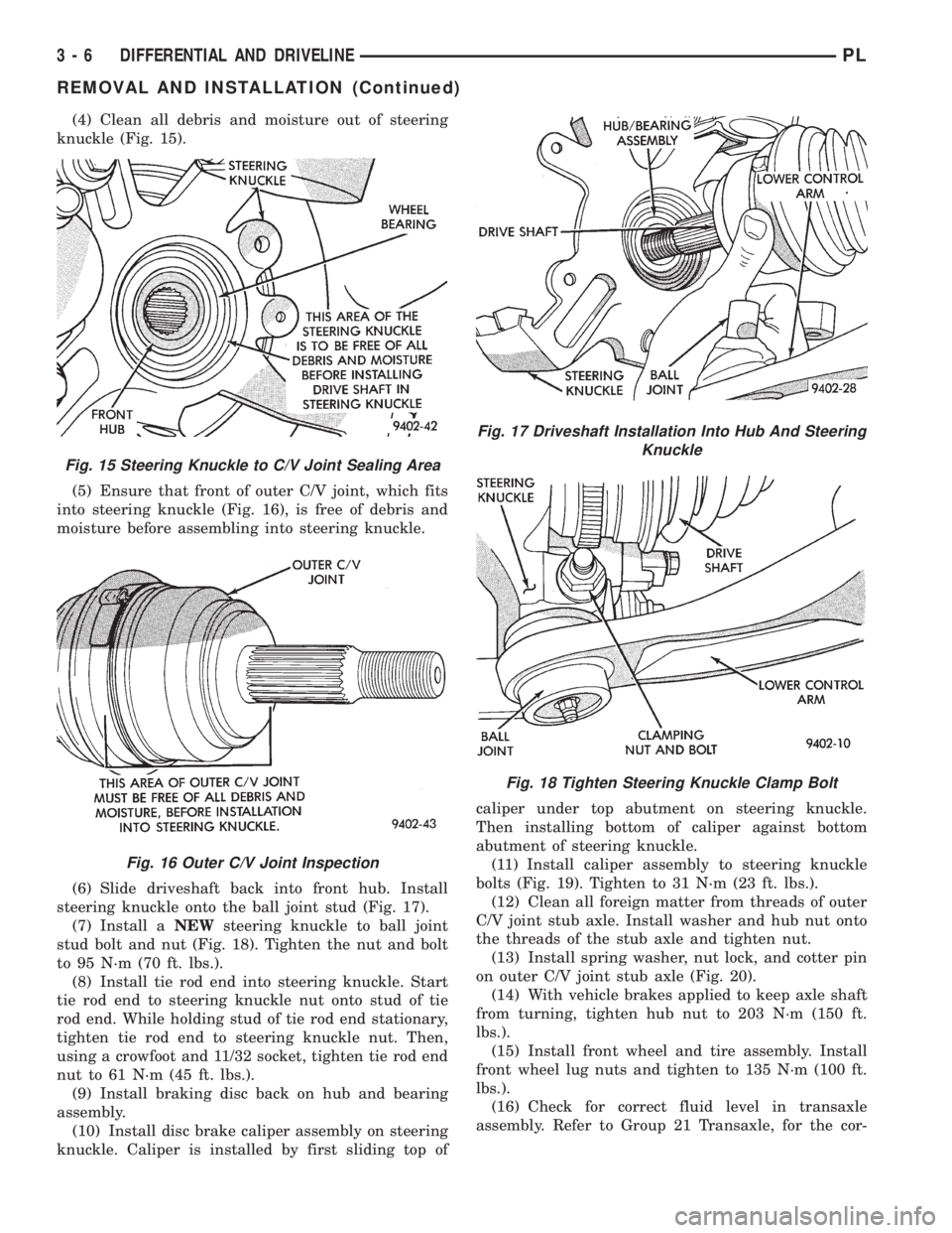
(4) Clean all debris and moisture out of steering
knuckle (Fig. 15).
(5) Ensure that front of outer C/V joint, which fits
into steering knuckle (Fig. 16), is free of debris and
moisture before assembling into steering knuckle.
(6) Slide driveshaft back into front hub. Install
steering knuckle onto the ball joint stud (Fig. 17).
(7) Install aNEWsteering knuckle to ball joint
stud bolt and nut (Fig. 18). Tighten the nut and bolt
to 95 N´m (70 ft. lbs.).
(8) Install tie rod end into steering knuckle. Start
tie rod end to steering knuckle nut onto stud of tie
rod end. While holding stud of tie rod end stationary,
tighten tie rod end to steering knuckle nut. Then,
using a crowfoot and 11/32 socket, tighten tie rod end
nut to 61 N´m (45 ft. lbs.).
(9) Install braking disc back on hub and bearing
assembly.
(10) Install disc brake caliper assembly on steering
knuckle. Caliper is installed by first sliding top ofcaliper under top abutment on steering knuckle.
Then installing bottom of caliper against bottom
abutment of steering knuckle.
(11) Install caliper assembly to steering knuckle
bolts (Fig. 19). Tighten to 31 N´m (23 ft. lbs.).
(12) Clean all foreign matter from threads of outer
C/V joint stub axle. Install washer and hub nut onto
the threads of the stub axle and tighten nut.
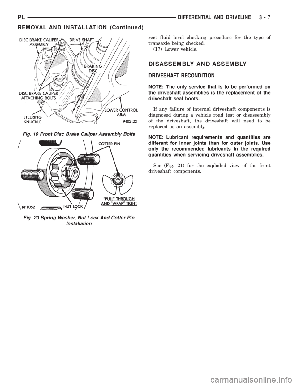
(13) Install spring washer, nut lock, and cotter pin
on outer C/V joint stub axle (Fig. 20).
(14) With vehicle brakes applied to keep axle shaft
from turning, tighten hub nut to 203 N´m (150 ft.
lbs.).
(15) Install front wheel and tire assembly. Install
front wheel lug nuts and tighten to 135 N´m (100 ft.
lbs.).
(16) Check for correct fluid level in transaxle
assembly. Refer to Group 21 Transaxle, for the cor-
Fig. 15 Steering Knuckle to C/V Joint Sealing Area
Fig. 16 Outer C/V Joint Inspection
Fig. 17 Driveshaft Installation Into Hub And Steering
Knuckle
Fig. 18 Tighten Steering Knuckle Clamp Bolt
3 - 6 DIFFERENTIAL AND DRIVELINEPL
REMOVAL AND INSTALLATION (Continued)
Page 72 of 1200
rect fluid level checking procedure for the type of
transaxle being checked.
(17) Lower vehicle.
DISASSEMBLY AND ASSEMBLY
DRIVESHAFT RECONDITION
NOTE: The only service that is to be performed on
the driveshaft assemblies is the replacement of the
driveshaft seal boots.
If any failure of internal driveshaft components is
diagnosed during a vehicle road test or disassembly
of the driveshaft, the driveshaft will need to be
replaced as an assembly.
NOTE: Lubricant requirements and quantities are
different for inner joints than for outer joints. Use
only the recommended lubricants in the required
quantities when servicing driveshaft assemblies.
See (Fig. 21) for the exploded view of the front
driveshaft components.
Fig. 19 Front Disc Brake Caliper Assembly Bolts
Fig. 20 Spring Washer, Nut Lock And Cotter Pin
Installation
PLDIFFERENTIAL AND DRIVELINE 3 - 7
REMOVAL AND INSTALLATION (Continued)
Page 128 of 1200
(9) Position master cylinder on studs of power
brake unit, aligning push rod on power brake vac-
uum booster with master cylinder push rod.
(10) Install the 2 master cylinder mounting nuts
(Fig. 117) and torque to 28 N´m (250 in. lbs.) torque.
(11) Connect brake tubes to master cylinder pri-
mary and secondary ports (Fig. 115) and (Fig. 116).
Torque all tube nuts to 17 N´m (145 in. lbs.) torque.
(12) Reconnect wiring connector to fluid level sen-
sor.
(13) Adjust stop lamp switch as necessary.
(14) Bleed brake system.
CHASSIS TUBES AND HOSES
Always use Mopar replacement brake hose assem-
blies to ensure quality, correct length and superior
fatigue life. Care should be taken to make sure that
the tube and hose mating surfaces are clean and free
from nicks and burrs.Hose assemblies for each
brake are unique and not interchangeable.
Use new copper seal washers on all connections
using Banjo Bolts and tighten all fittings to their
specified torques.
The flexible front hydraulic brake hose should
always be installed on the vehicle by first attaching
the Banjo connector to the caliper assembly. Then
bolt the intermediate hose bracket to the strut
assembly allowing the bracket to position the hose to
prevent twisting. Attach the hose to brake tubing,
before attaching to front frame rail. Then tighten all
brake line fittings to specified torque.
On vehicles equipped with rear drum brakes,
install rear brake hoses first to wheel cylinders and
rear struts and then attach hose bracket to body. On
vehicles equipped with rear disc brakes, attach brake
hoses to calipers and struts first and then attach
brake hose bracket to body. Following this procedure
will reduce potential for twisting brake during instal-
lation procedure.
Only double wall 4.75mm (3/16 in.) steel brake line
tubing, with Al- Rich/ZN-AL alloy coating should be
used for replacement. Care must be taken when
replacing brake tubing, to be sure the proper bending
and flaring tools and procedures are used to avoid
kinking. Do not route the tubes against sharp edges,
moving components or into hot areas. All tubes
should be properly attached with recommended
retaining clips.
PROPORTIONING VALVE (BASE BRAKES)
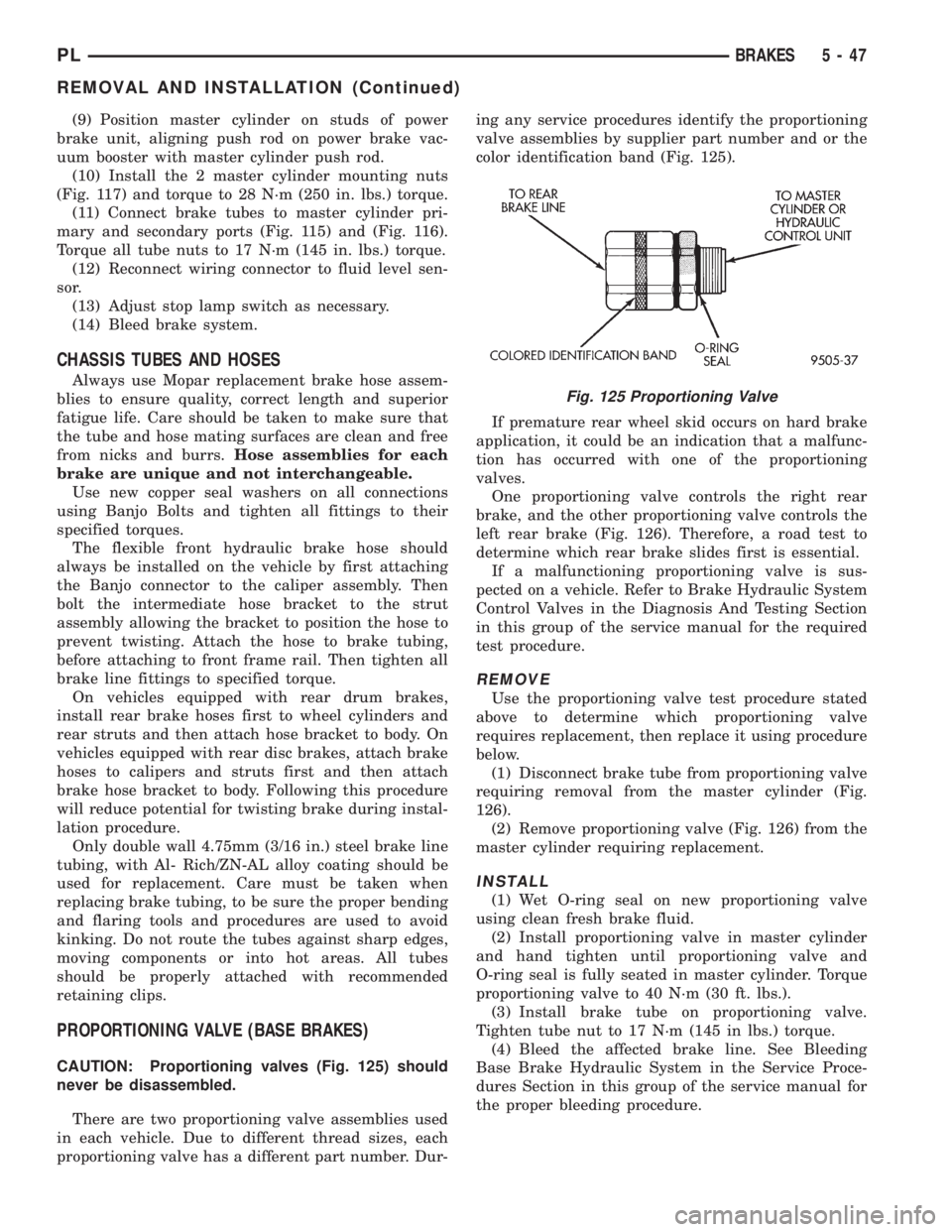
CAUTION: Proportioning valves (Fig. 125) should
never be disassembled.
There are two proportioning valve assemblies used
in each vehicle. Due to different thread sizes, each
proportioning valve has a different part number. Dur-ing any service procedures identify the proportioning
valve assemblies by supplier part number and or the
color identification band (Fig. 125).
If premature rear wheel skid occurs on hard brake
application, it could be an indication that a malfunc-
tion has occurred with one of the proportioning
valves.
One proportioning valve controls the right rear
brake, and the other proportioning valve controls the
left rear brake (Fig. 126). Therefore, a road test to
determine which rear brake slides first is essential.
If a malfunctioning proportioning valve is sus-
pected on a vehicle. Refer to Brake Hydraulic System
Control Valves in the Diagnosis And Testing Section
in this group of the service manual for the required
test procedure.
REMOVE
Use the proportioning valve test procedure stated
above to determine which proportioning valve
requires replacement, then replace it using procedure
below.
(1) Disconnect brake tube from proportioning valve
requiring removal from the master cylinder (Fig.
126).
(2) Remove proportioning valve (Fig. 126) from the
master cylinder requiring replacement.
INSTALL
(1) Wet O-ring seal on new proportioning valve
using clean fresh brake fluid.
(2) Install proportioning valve in master cylinder
and hand tighten until proportioning valve and
O-ring seal is fully seated in master cylinder. Torque
proportioning valve to 40 N´m (30 ft. lbs.).
(3) Install brake tube on proportioning valve.
Tighten tube nut to 17 N´m (145 in lbs.) torque.
(4) Bleed the affected brake line. See Bleeding
Base Brake Hydraulic System in the Service Proce-
dures Section in this group of the service manual for
the proper bleeding procedure.
Fig. 125 Proportioning Valve
PLBRAKES 5 - 47
REMOVAL AND INSTALLATION (Continued)
Page 143 of 1200
(12) Inspect caliper piston for pitting, scratches, or
any physical damage. Replace piston if there is evi-
dence of scratches, pitting or physical damage.
CALIPER ASSEMBLY
CAUTION: Excessive vise pressure will cause bore
distortion and binding of piston.
(1) Clamp caliper in a vise (with protective caps
installed on jaws of vise).
(2) Dip new piston seal in clean brake fluid and
install in the groove of the caliper bore. Seal should
be positioned at one area in groove and gently
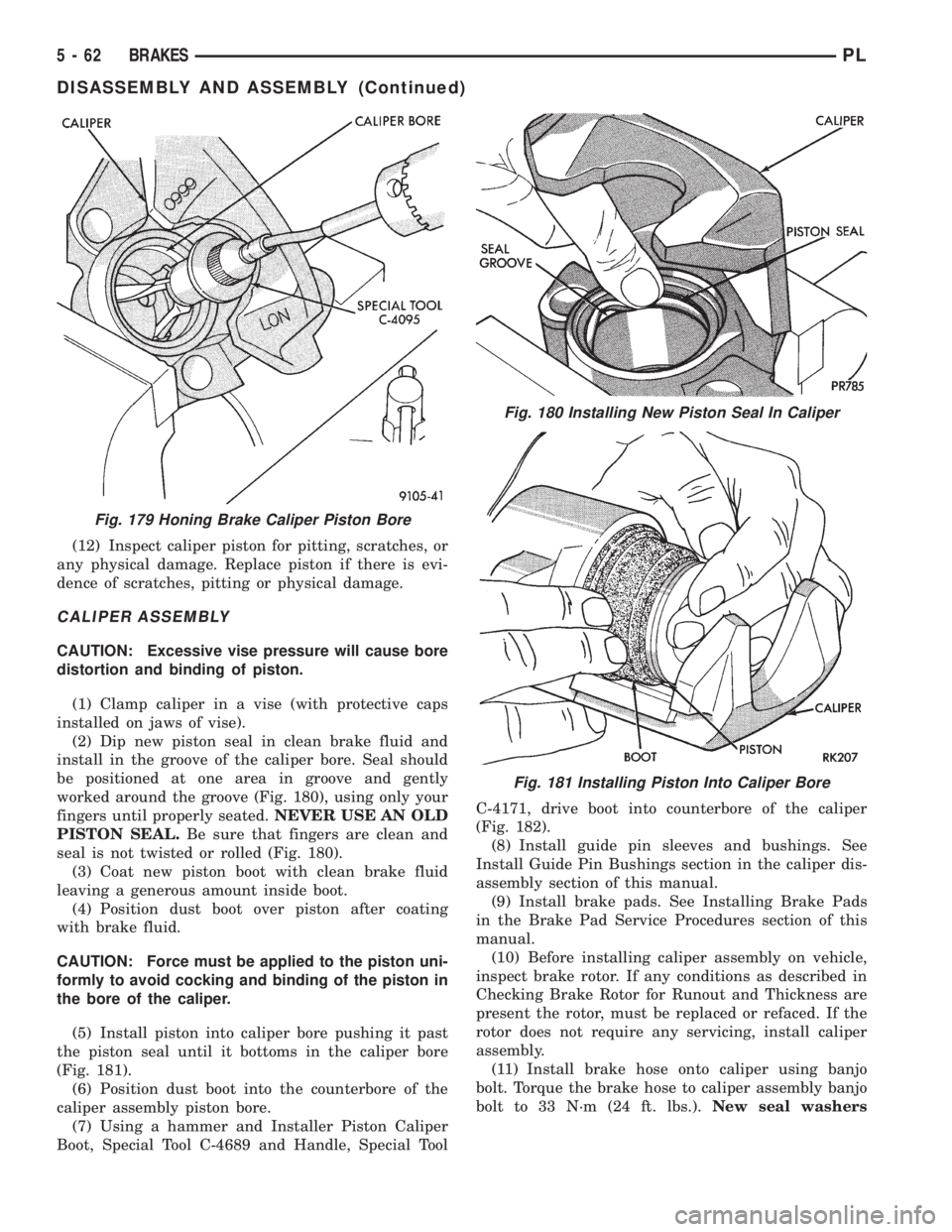
worked around the groove (Fig. 180), using only your
fingers until properly seated.NEVER USE AN OLD
PISTON SEAL.Be sure that fingers are clean and
seal is not twisted or rolled (Fig. 180).
(3) Coat new piston boot with clean brake fluid
leaving a generous amount inside boot.
(4) Position dust boot over piston after coating
with brake fluid.
CAUTION: Force must be applied to the piston uni-
formly to avoid cocking and binding of the piston in
the bore of the caliper.
(5) Install piston into caliper bore pushing it past
the piston seal until it bottoms in the caliper bore
(Fig. 181).
(6) Position dust boot into the counterbore of the
caliper assembly piston bore.
(7) Using a hammer and Installer Piston Caliper
Boot, Special Tool C-4689 and Handle, Special ToolC-4171, drive boot into counterbore of the caliper
(Fig. 182).
(8) Install guide pin sleeves and bushings. See
Install Guide Pin Bushings section in the caliper dis-
assembly section of this manual.
(9) Install brake pads. See Installing Brake Pads
in the Brake Pad Service Procedures section of this
manual.
(10) Before installing caliper assembly on vehicle,
inspect brake rotor. If any conditions as described in
Checking Brake Rotor for Runout and Thickness are
present the rotor, must be replaced or refaced. If the
rotor does not require any servicing, install caliper
assembly.
(11) Install brake hose onto caliper using banjo
bolt. Torque the brake hose to caliper assembly banjo
bolt to 33 N´m (24 ft. lbs.).New seal washers
Fig. 179 Honing Brake Caliper Piston Bore
Fig. 180 Installing New Piston Seal In Caliper
Fig. 181 Installing Piston Into Caliper Bore
5 - 62 BRAKESPL
DISASSEMBLY AND ASSEMBLY (Continued)
Page 181 of 1200
INSTALLATION
(1) The pivot ball pocket in the fork is Teflon
coated and should be installed WITHOUT any lubri-
cant such as grease. Using grease will break down
the Teflon coating. Be sure the ball stud and fork
pocket are clean of contamination and dirt.
(2) Assemble the fork to the bearing. The small
pegs on the bearing must go over the fork arms.
(3) Slide the bearing and fork assembly onto the
input shaft bearing retainer, as a unit.
(4) Snap the clutch fork onto the pivot ball.
(5) Reinstall transaxle assembly. Refer to Group
21, Transaxle for further information.
CLEANING AND INSPECTION
CLUTCH CONTAMINATION
Fluid contamination is a frequent cause of clutch
malfunctions. Oil, grease, water, or other fluids on
the clutch contact surfaces will cause faulty opera-
tion.
During inspection, note if any components are con-
taminated. Look for evidence of oil, grease, or water/
road splash on clutch components.
OIL CONTAMINATION
Oil contamination indicates a leak at the rear main
seal and/or transaxle input shaft. Oil leaks produce a
residue of oil on the transaxle housing interior, clutch
cover and flywheel. Heat buildup caused by slippage
can bake the oil residue onto the components. This
glaze-like residue ranges in color from amber to
black.
GREASE CONTAMINATION
Grease contamination is usually a product of over-
lubrication. During clutch service, apply only a small
amount of grease to the input shaft splines. Excess
grease may be thrown off during operation, contami-
nating the disc.
ROAD SPLASH/WATER CONTAMINATION
Road splash contamination is usually caused by
driving the vehicle through deep water puddles.
Water can be forced into the clutch housing, causing
clutch components to become contaminated. Facing of
disc will absorb moisture and bond to the flywheel
and/or, pressure plate, if vehicle is allowed to stand
for some time before use. If this condition occurs,
replacement of clutch assembly may be required.
Drive the vehicle until normal clutch operating tem-
perature has been obtained. This will dry off disc
assembly, pressure plate, and flywheel.
CLEANING PRECAUTIONS
Condensation from steam vapors tend to accumu-
late on the internal clutch mechanism when the vehi-
cle is steam cleaned. Facing of disc will absorb
moisture and will bond to flywheel and/or pressure
plate, if vehicle is allowed to stand for some time
before use. If this condition occurs, it may require
replacement of clutch assembly. After cleaning, drive
the vehicle to its normal clutch operating tempera-
ture. This will dry off disc assembly, pressure plate,
and flywheel.
ADJUSTMENTS
CLUTCH CABLE
The manual transaxle clutch release system has a
unique self-adjusting mechanism to compensate for
clutch disc wear. This adjuster mechanism is located
within the clutch cable assembly. The preload spring
maintains tension on the cable. This tension keeps
the clutch release bearing continuously loaded
against the fingers of the clutch cover assembly.
ADJUSTER MECHANISM FUNCTION CHECK
(1) With slight pressure, pull the clutch release
lever end of the cable to draw the cable taut. Push
the clutch cable housing toward the dash panel. With
less than 25 lbs. of effort the cable housing should
move 30-50mm. This indicates proper adjuster mech-
anism function. If the cable does not adjust, deter-
mine if the mechanism is properly seated on the
bracket.
(2) If the adjust mechanism functions properly,
guide the cable through the slot in the transaxle
housing. Connect cable to release lever, seating the
cupped washer securely on lever tangs.
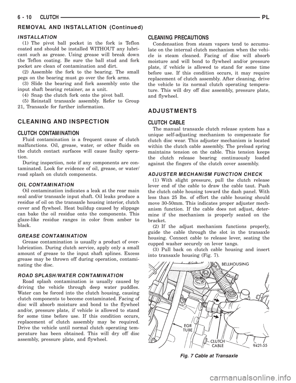
(3) Pull back on clutch cable housing and insert
into transaxle housing (Fig. 7).
Fig. 7 Cable at Transaxle
6 - 10 CLUTCHPL
REMOVAL AND INSTALLATION (Continued)
Page 261 of 1200
other operating conditions are causing engine over-
heating.
SPARK PLUG OVERHEATING
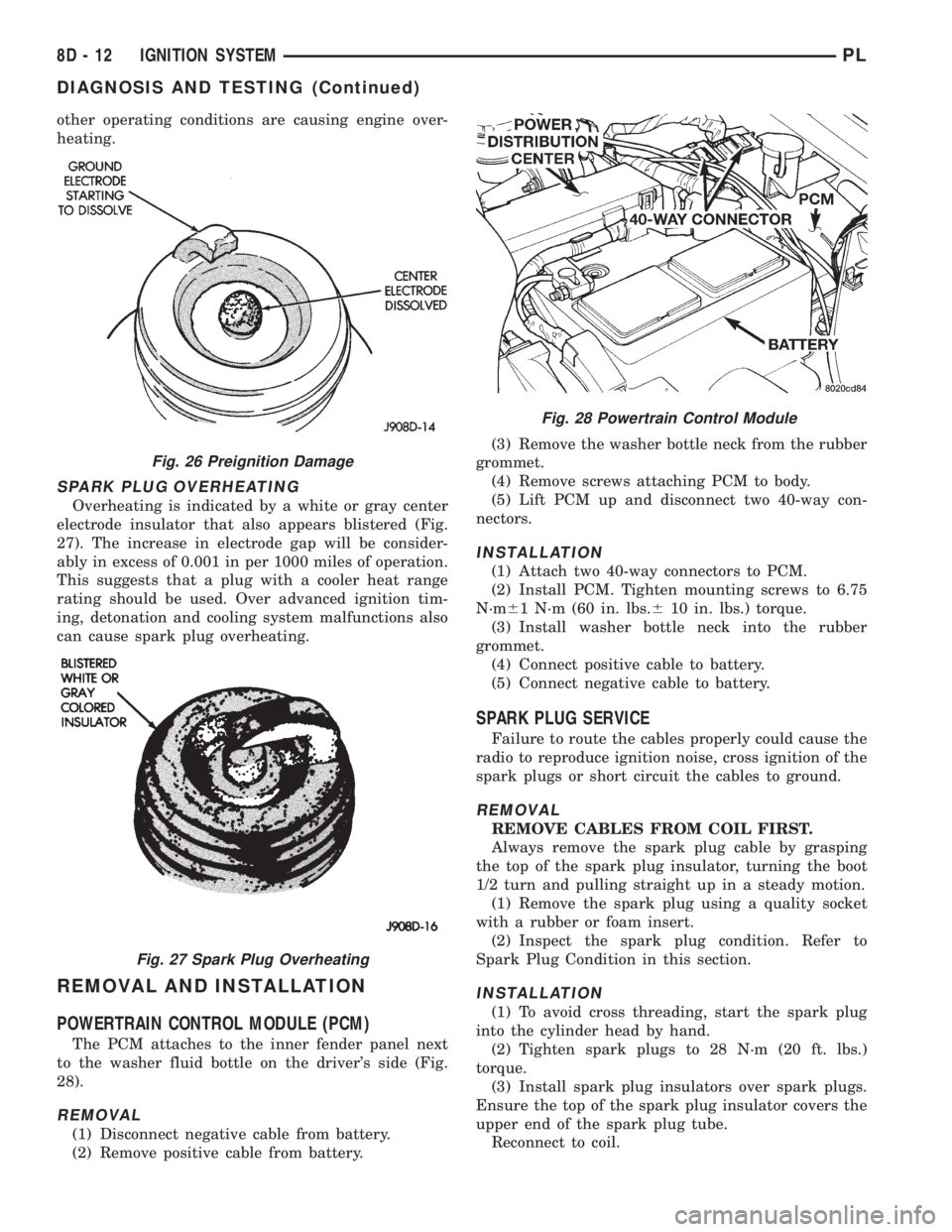
Overheating is indicated by a white or gray center
electrode insulator that also appears blistered (Fig.
27). The increase in electrode gap will be consider-
ably in excess of 0.001 in per 1000 miles of operation.
This suggests that a plug with a cooler heat range
rating should be used. Over advanced ignition tim-
ing, detonation and cooling system malfunctions also
can cause spark plug overheating.
REMOVAL AND INSTALLATION
POWERTRAIN CONTROL MODULE (PCM)
The PCM attaches to the inner fender panel next
to the washer fluid bottle on the driver's side (Fig.
28).
REMOVAL
(1) Disconnect negative cable from battery.
(2) Remove positive cable from battery.(3) Remove the washer bottle neck from the rubber
grommet.
(4) Remove screws attaching PCM to body.
(5) Lift PCM up and disconnect two 40-way con-
nectors.
INSTALLATION
(1) Attach two 40-way connectors to PCM.
(2) Install PCM. Tighten mounting screws to 6.75
N´m61 N´m (60 in. lbs.610 in. lbs.) torque.
(3) Install washer bottle neck into the rubber
grommet.
(4) Connect positive cable to battery.
(5) Connect negative cable to battery.
SPARK PLUG SERVICE
Failure to route the cables properly could cause the
radio to reproduce ignition noise, cross ignition of the
spark plugs or short circuit the cables to ground.
REMOVAL
REMOVE CABLES FROM COIL FIRST.
Always remove the spark plug cable by grasping
the top of the spark plug insulator, turning the boot
1/2 turn and pulling straight up in a steady motion.
(1) Remove the spark plug using a quality socket
with a rubber or foam insert.
(2) Inspect the spark plug condition. Refer to
Spark Plug Condition in this section.
INSTALLATION
(1) To avoid cross threading, start the spark plug
into the cylinder head by hand.
(2) Tighten spark plugs to 28 N´m (20 ft. lbs.)
torque.
(3) Install spark plug insulators over spark plugs.
Ensure the top of the spark plug insulator covers the
upper end of the spark plug tube.
Reconnect to coil.
Fig. 26 Preignition Damage
Fig. 27 Spark Plug Overheating
Fig. 28 Powertrain Control Module
8D - 12 IGNITION SYSTEMPL
DIAGNOSIS AND TESTING (Continued)
Page 321 of 1200
WINDSHIELD WASHER SYSTEM
INDEX
page page
DESCRIPTION AND OPERATION
WASHER NOZZLE........................ 8
DIAGNOSIS AND TESTING
WINDSHIELD WASHERS................... 8REMOVAL AND INSTALLATION
WASHER NOZZLE........................ 9
WASHER RESERVOIR PUMP.............. 10
WASHER RESERVOIR..................... 9
DESCRIPTION AND OPERATION
WASHER NOZZLE
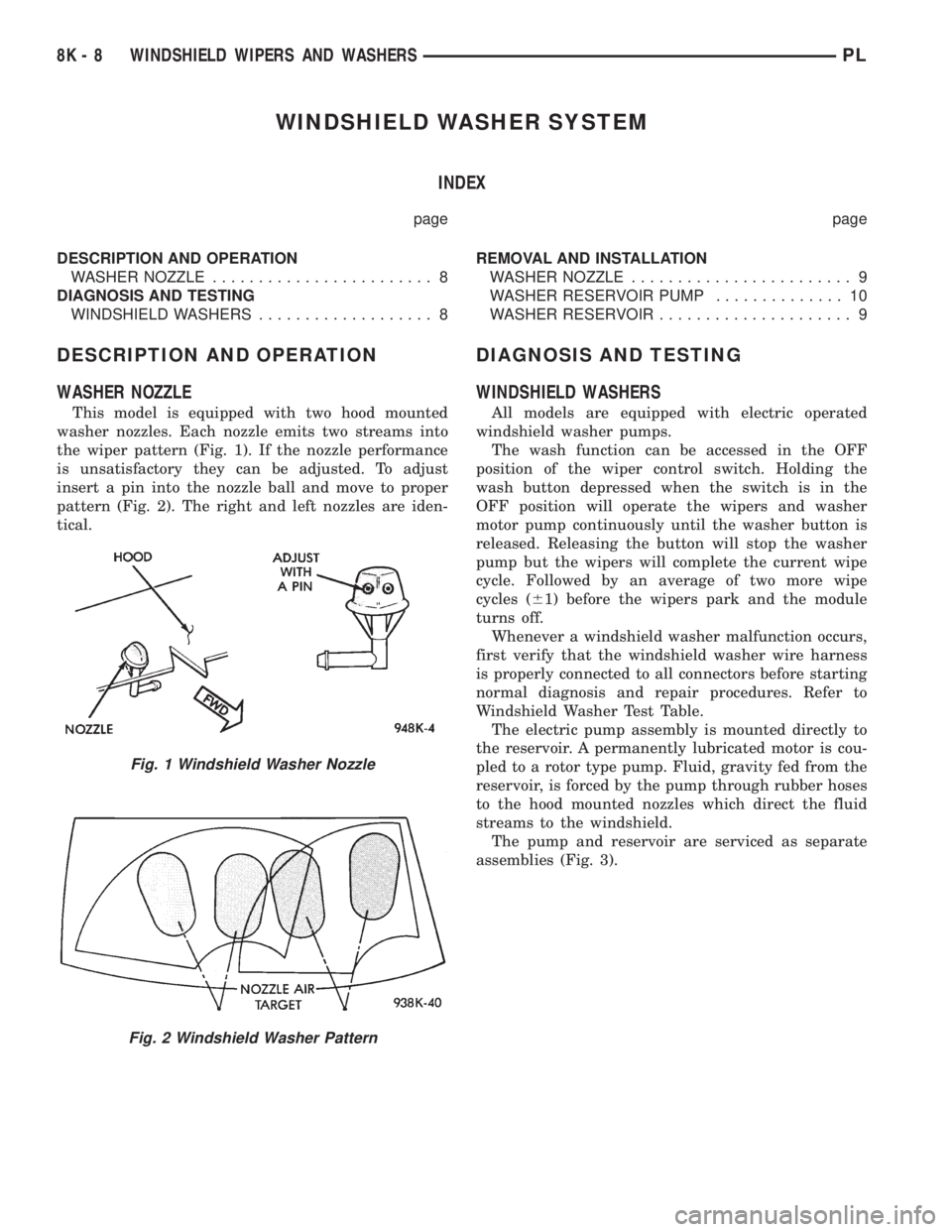
This model is equipped with two hood mounted
washer nozzles. Each nozzle emits two streams into
the wiper pattern (Fig. 1). If the nozzle performance
is unsatisfactory they can be adjusted. To adjust
insert a pin into the nozzle ball and move to proper
pattern (Fig. 2). The right and left nozzles are iden-
tical.
DIAGNOSIS AND TESTING
WINDSHIELD WASHERS
All models are equipped with electric operated
windshield washer pumps.
The wash function can be accessed in the OFF
position of the wiper control switch. Holding the
wash button depressed when the switch is in the
OFF position will operate the wipers and washer
motor pump continuously until the washer button is
released. Releasing the button will stop the washer
pump but the wipers will complete the current wipe
cycle. Followed by an average of two more wipe
cycles (61) before the wipers park and the module
turns off.
Whenever a windshield washer malfunction occurs,
first verify that the windshield washer wire harness
is properly connected to all connectors before starting
normal diagnosis and repair procedures. Refer to
Windshield Washer Test Table.
The electric pump assembly is mounted directly to
the reservoir. A permanently lubricated motor is cou-
pled to a rotor type pump. Fluid, gravity fed from the
reservoir, is forced by the pump through rubber hoses
to the hood mounted nozzles which direct the fluid
streams to the windshield.
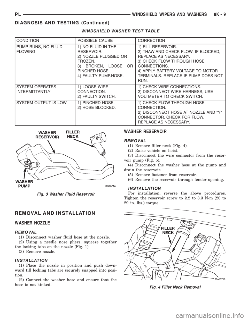
The pump and reservoir are serviced as separate
assemblies (Fig. 3).
Fig. 1 Windshield Washer Nozzle
Fig. 2 Windshield Washer Pattern
8K - 8 WINDSHIELD WIPERS AND WASHERSPL
Page 322 of 1200
REMOVAL AND INSTALLATION
WASHER NOZZLE
REMOVAL
(1) Disconnect washer fluid hose at the nozzle.
(2) Using a needle nose pliers, squeeze together
the locking tabs on the nozzle (Fig. 1).
(3) Remove nozzle.
INSTALLATION
(1) Place the nozzle in position and push down-
ward till locking tabs are securely snapped into posi-
tion.
(2) Connect the washer hose and ensure that the
hose is not kinked.
WASHER RESERVOIR
REMOVAL
(1) Remove filler neck (Fig. 4).
(2) Raise vehicle on hoist.
(3) Disconnect the wire connector from the reser-
voir pump (Fig. 5).
(4) Disconnect the washer hose at the pump and
drain the reservoir.
(5) Remove fastener from reservoir.
(6) Remove the reservoir through fender opening.
INSTALLATION
For installation, reverse the above procedures.
Tighten the reservoir screw to 2.2 to 3.3 N´m (20 to
29 in. lbs.) torque.
WINDSHIELD WASHER TEST TABLE
CONDITION POSSIBLE CAUSE CORRECTION
PUMP RUNS, NO FLUID
FLOWING1) NO FLUID IN THE
RESERVOIR.
2) NOZZLE PLUGGED OR
FROZEN.
3) BROKEN, LOOSE OR
PINCHED HOSE.
4) FAULTY PUMP.HOSE.1) FILL RESERVOIR.
2) THAW AND CHECK FLOW. IF BLOCKED,
REPLACE AS NECESSARY.
3) CHECK FLOW THROUGH HOSE
CONNECTIONS.
4) APPLY BATTERY VOLTAGE TO MOTOR
TERMINALS. REPLACE IF PUMP DOES NOT
RUN.
SYSTEM OPERATES
INTERMITTANTLY1) LOOSE WIRE
CONNECTION.
2) FAULTY SWITCH.1) CHECK WIRE CONNECTIONS.
2) DISCONNECT WIRE HARNESS, USE
VOLTMETER TO CHECK SWITCH.
SYSTEM OUTPUT IS LOW 1) PINCHED HOSE.
2) HOSE BLOCKED.1) CHECK FLOW THROUGH HOSE
CONNECTION.
2) DISCONNECT HOSE AT NOZZLE AND9Y9
CONNECTOR. CHECK FOR FLOW.
REPLACE AS NECESSARY.
Fig. 3 Washer Fluid Reservoir
Fig. 4 Filler Neck Removal
PLWINDSHIELD WIPERS AND WASHERS 8K - 9
DIAGNOSIS AND TESTING (Continued)