jump start DODGE NEON 1999 Service Repair Manual
[x] Cancel search | Manufacturer: DODGE, Model Year: 1999, Model line: NEON, Model: DODGE NEON 1999Pages: 1200, PDF Size: 35.29 MB
Page 2 of 1200
LUBRICATION AND MAINTENANCE
CONTENTS
page page
GENERAL INFORMATION................... 1
JUMP STARTING, TOWING AND HOISTING.... 7MAINTENANCE SCHEDULES................ 3
GENERAL INFORMATION
INDEX
page page
GENERAL INFORMATION
CLASSIFICATION OF LUBRICANTS........... 1
FLUID CAPACITIES....................... 2
INTERNATIONAL SYMBOLS................ 1INTRODUCTION......................... 1
PARTS AND LUBRICANT
RECOMMENDATIONS.................... 1
GENERAL INFORMATION
INTRODUCTION
Service and maintenance procedures for compo-
nents and systems listed in Schedule ± A or B can be
found by using the Group Tab Locator index at the
front of this manual. If it is not clear which group
contains the information needed, refer to the index at
the back of this manual.
There are two maintenance schedules that show
proper service based on the conditions that the vehi-
cle is subjected to.
Schedule ±A, lists scheduled maintenance to be
performed when the vehicle is used for general trans-
portation.
Schedule ±B, lists maintenance intervals for vehi-
cles that are operated under the conditions listed at
the beginning of the Maintenance Schedule section.
Use the schedule that best describes your driving
conditions.
Where time and mileage are listed, follow the
interval that occurs first.
PARTS AND LUBRICANT RECOMMENDATIONS
When service is required, Chrysler Corporation
recommends that only Mopartbrand parts, lubri-
cants and chemicals be used. Mopar provides the
best engineered products for servicing Chrysler Cor-
poration vehicles.
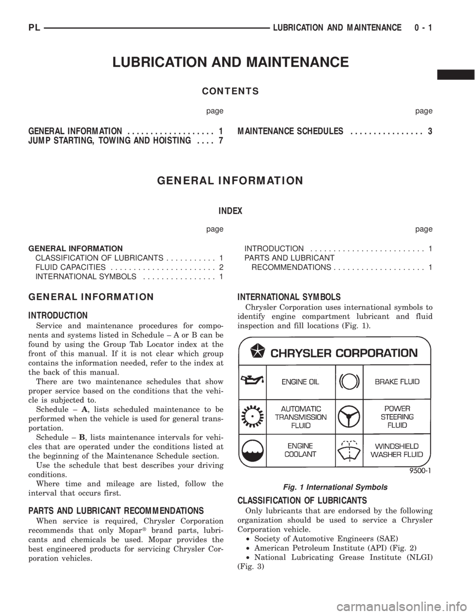
INTERNATIONAL SYMBOLS
Chrysler Corporation uses international symbols to
identify engine compartment lubricant and fluid
inspection and fill locations (Fig. 1).
CLASSIFICATION OF LUBRICANTS
Only lubricants that are endorsed by the following
organization should be used to service a Chrysler
Corporation vehicle.
²Society of Automotive Engineers (SAE)
²American Petroleum Institute (API) (Fig. 2)
²National Lubricating Grease Institute (NLGI)
(Fig. 3)
Fig. 1 International Symbols
PLLUBRICATION AND MAINTENANCE 0 - 1
Page 8 of 1200
JUMP STARTING, TOWING AND HOISTING
INDEX
page page
SERVICE PROCEDURES
HOISTING RECOMMENDATIONS............ 9JUMP STARTING PROCEDURE.............. 7
TOWING RECOMMENDATIONS.............. 8
SERVICE PROCEDURES
JUMP STARTING PROCEDURE
WARNING: REVIEW ALL SAFETY PRECAUTIONS
AND WARNINGS IN GROUP 8A, BATTERY/START-
ING/CHARGING SYSTEMS DIAGNOSTICS. DO NOT
JUMP START A FROZEN BATTERY, PERSONAL
INJURY CAN RESULT. DO NOT JUMP START WHEN
MAINTENANCE FREE BATTERY INDICATOR DOT IS
YELLOW OR BRIGHT COLOR. DO NOT JUMP
START A VEHICLE WHEN THE BATTERY FLUID IS
BELOW THE TOP OF LEAD PLATES. DO NOT
ALLOW JUMPER CABLE CLAMPS TO TOUCH
EACH OTHER WHEN CONNECTED TO A BOOSTER
SOURCE. DO NOT USE OPEN FLAME NEAR BAT-
TERY. REMOVE METALLIC JEWELRY WORN ON
HANDS OR WRISTS TO AVOID INJURY BY ACCI-
DENTAL ARCING OF BATTERY CURRENT. WHEN
USING A HIGH OUTPUT BOOSTING DEVICE, DO
NOT ALLOW BATTERY VOLTAGE TO EXCEED 16
VOLTS. REFER TO INSTRUCTIONS PROVIDED
WITH DEVICE BEING USED.
CAUTION: When using another vehicle as a
booster, do not allow vehicles to touch. Electrical
systems can be damaged on either vehicle.
TO JUMP START A DISABLED VEHICLE:
(1) Raise hood on disabled vehicle and visually
inspect engine compartment for:
²Battery cable clamp condition, clean if necessary.
²Frozen battery.
²Yellow or bright color test indicator, if equipped.
²Low battery fluid level.
²Generator drive belt condition and tension.
²Fuel fumes or leakage, correct if necessary.
CAUTION: If the cause of starting problem on dis-
abled vehicle is severe, damage to booster vehicle
charging system can result.
(2) When using another vehicle as a booster
source, park the booster vehicle within cable reach.
Turn off all accessories, set the parking brake, placethe automatic transmission in PARK or the manual
transmission in NEUTRAL and turn the ignition
OFF.
(3) On disabled vehicle, place gear selector in park
or neutral and set park brake. Turn off all accesso-
ries.
(4) Connect jumper cables to booster battery. RED
clamp to positive terminal (+). BLACK clamp to neg-
ative terminal (-). DO NOT allow clamps at opposite
end of cables to touch, electrical arc will result.
Review all warnings in this procedure.
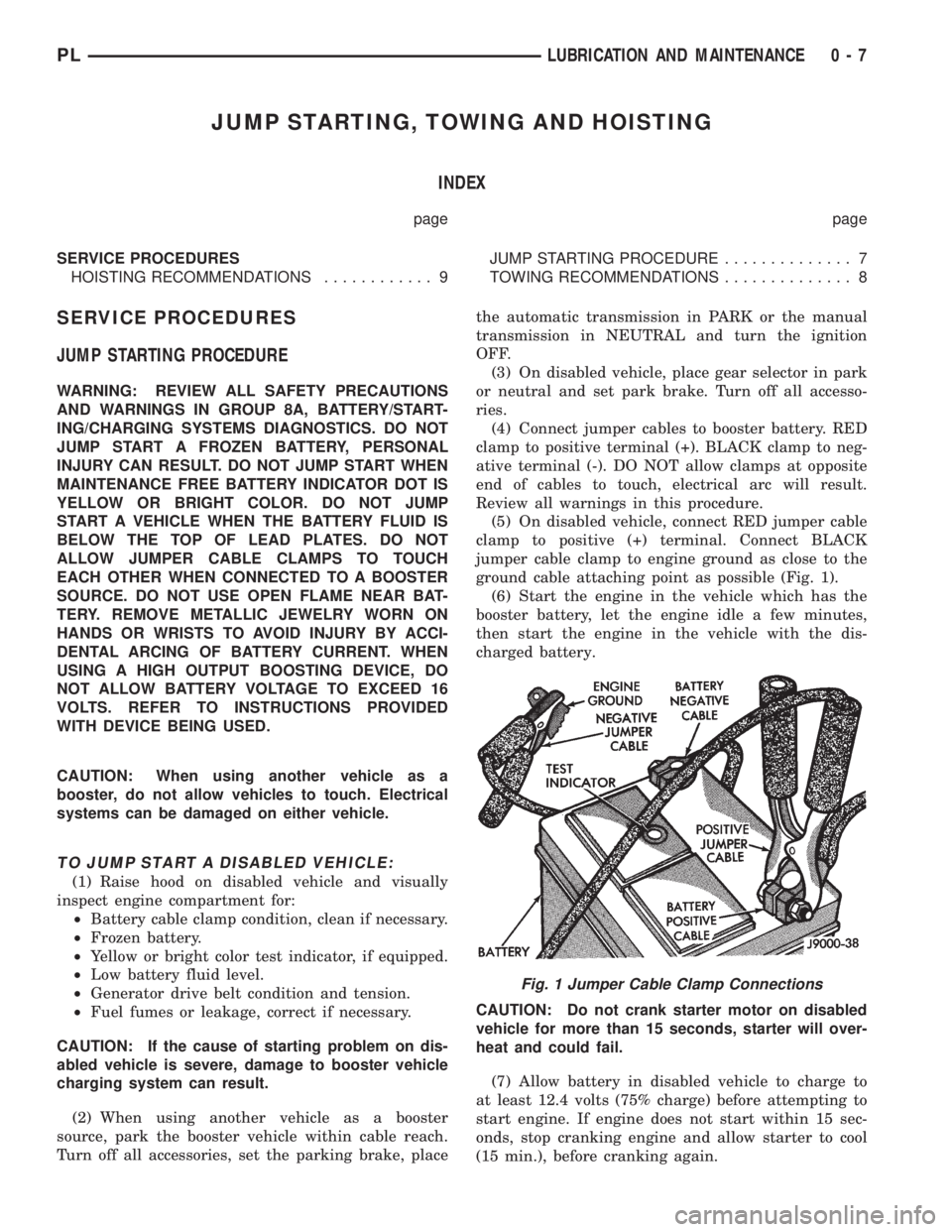
(5) On disabled vehicle, connect RED jumper cable
clamp to positive (+) terminal. Connect BLACK
jumper cable clamp to engine ground as close to the
ground cable attaching point as possible (Fig. 1).
(6) Start the engine in the vehicle which has the
booster battery, let the engine idle a few minutes,
then start the engine in the vehicle with the dis-
charged battery.
CAUTION: Do not crank starter motor on disabled
vehicle for more than 15 seconds, starter will over-
heat and could fail.
(7) Allow battery in disabled vehicle to charge to
at least 12.4 volts (75% charge) before attempting to
start engine. If engine does not start within 15 sec-
onds, stop cranking engine and allow starter to cool
(15 min.), before cranking again.
Fig. 1 Jumper Cable Clamp Connections
PLLUBRICATION AND MAINTENANCE 0 - 7
Page 271 of 1200
When the ignition switch is in the OFF position, or
when the radio frequency is being displayed, time
keeping is accurately maintained.
The procedure for setting the clock varies slightly
with each radio. The correct procedure is described in
the individual radio operating instructions. Refer to
the Owner's Manual supplied with the vehicle.
INSTRUMENT CLUSTER
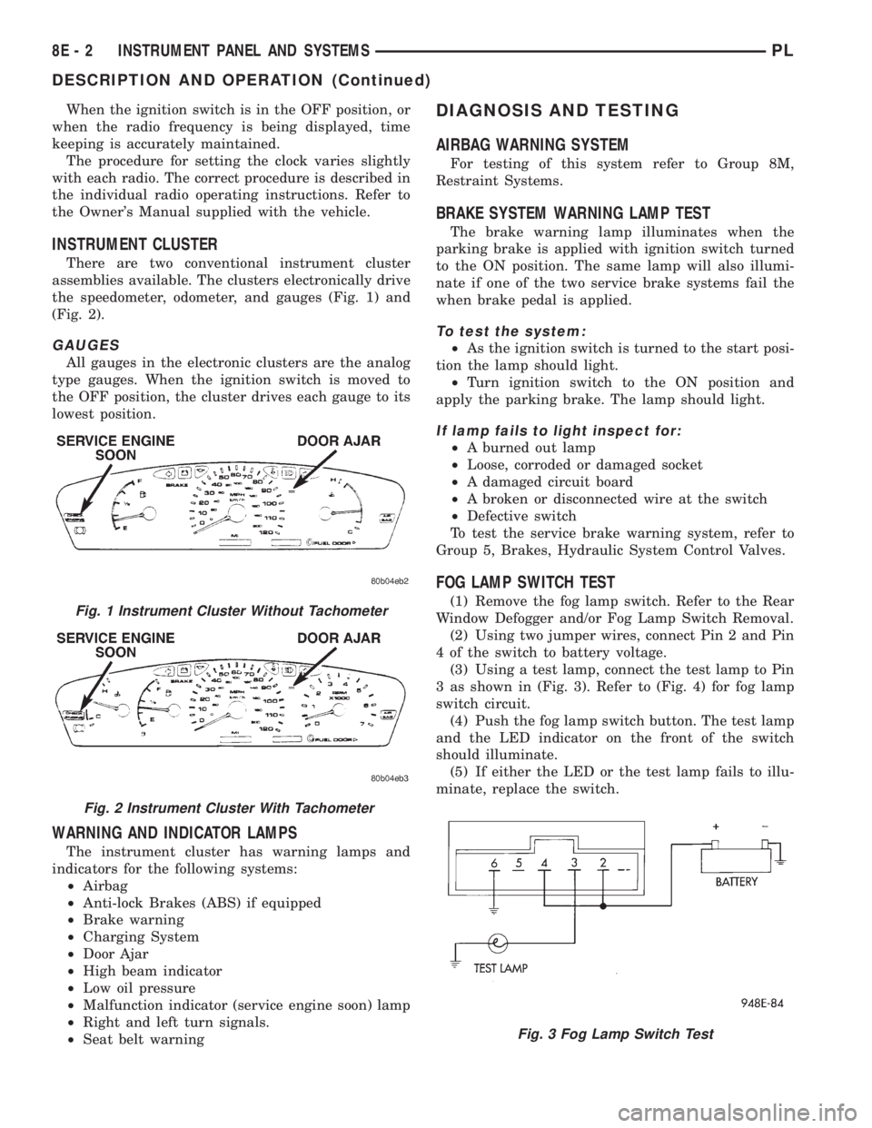
There are two conventional instrument cluster
assemblies available. The clusters electronically drive
the speedometer, odometer, and gauges (Fig. 1) and
(Fig. 2).
GAUGES
All gauges in the electronic clusters are the analog
type gauges. When the ignition switch is moved to
the OFF position, the cluster drives each gauge to its
lowest position.
WARNING AND INDICATOR LAMPS
The instrument cluster has warning lamps and
indicators for the following systems:
²Airbag
²Anti-lock Brakes (ABS) if equipped
²Brake warning
²Charging System
²Door Ajar
²High beam indicator
²Low oil pressure
²Malfunction indicator (service engine soon) lamp
²Right and left turn signals.
²Seat belt warning
DIAGNOSIS AND TESTING
AIRBAG WARNING SYSTEM
For testing of this system refer to Group 8M,
Restraint Systems.
BRAKE SYSTEM WARNING LAMP TEST
The brake warning lamp illuminates when the
parking brake is applied with ignition switch turned
to the ON position. The same lamp will also illumi-
nate if one of the two service brake systems fail the
when brake pedal is applied.
To test the system:
²As the ignition switch is turned to the start posi-
tion the lamp should light.
²Turn ignition switch to the ON position and
apply the parking brake. The lamp should light.
If lamp fails to light inspect for:
²A burned out lamp
²Loose, corroded or damaged socket
²A damaged circuit board
²A broken or disconnected wire at the switch
²Defective switch
To test the service brake warning system, refer to
Group 5, Brakes, Hydraulic System Control Valves.
FOG LAMP SWITCH TEST
(1) Remove the fog lamp switch. Refer to the Rear
Window Defogger and/or Fog Lamp Switch Removal.
(2) Using two jumper wires, connect Pin 2 and Pin
4 of the switch to battery voltage.
(3) Using a test lamp, connect the test lamp to Pin
3 as shown in (Fig. 3). Refer to (Fig. 4) for fog lamp
switch circuit.
(4) Push the fog lamp switch button. The test lamp
and the LED indicator on the front of the switch
should illuminate.
(5) If either the LED or the test lamp fails to illu-
minate, replace the switch.Fig. 1 Instrument Cluster Without Tachometer
Fig. 2 Instrument Cluster With Tachometer
Fig. 3 Fog Lamp Switch Test
8E - 2 INSTRUMENT PANEL AND SYSTEMSPL
DESCRIPTION AND OPERATION (Continued)
Page 303 of 1200
OVERSHOOT/UNDERSHOOT FOLLOWING SPEED
CONTROL SET
If the operator repeatedly presses and releases the
set button with their foot off of the accelerator (a ªlift
foot setº to begin speed control operation), the vehicle
may accelerate and exceed the desired set speed by
up to 5 MPH (8 km/h) and then decelerate to less
than the desired set speed before finally achieving
the desired set speed.
The Speed Control has an adaptive strategy that
compensates for vehicle-to-vehicle variations in speed
control cable lengths. When the speed control is set
with the vehicle operators foot off of the accelerator
pedal, the speed control thinks there is excessive
speed control cable slack and adapts. If the lift foot
sets are continually used, the speed control over-
shoot/undershoot condition will develop.
To ªunlearnº the overshoot/undershoot condition,
the vehicle operator has to press and release the set
button while maintaining the desired set speed with
the accelerator pedal (not decelerating or accelerat-
ing), and then turn the cruise control switch to the
OFF position (or press the CANCEL button if
equipped) after waiting 10 seconds. This procedure
must be performed approximately 10±15 times to
completely unlearn the overshoot/undershoot condi-
tion.
SERVO VACUUM TEST
(1) Turn ignition switch to the ON position with-
out starting engine. Activate speed control ON
switch.
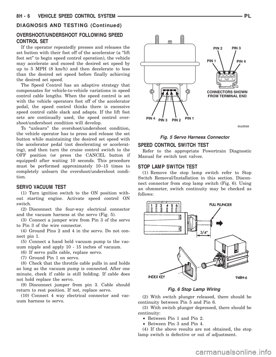
(2) Disconnect the four-way electrical connector
and the vacuum harness at the servo (Fig. 5).
(3) Connect a jumper wire from Pin 3 of the servo
to Pin 3 of the wire connector.
(4) Ground Pins 2 and 4 in the servo. Do not con-
nect pin 1.
(5) Connect a hand held vacuum pump to the vac-
uum nipple and apply 10 - 15 inches of vacuum.
(6) If servo pulls cable, replace servo.
(7) Ground Pin 1 on servo.
(8) Check that the throttle cable pulls in and holds
as long as the vacuum pump is connected. After one
minute, check if cable is still holding. If cable does
not hold replace the servo.
(9) Disconnect jumper from pin 3. Cable should
return to rest position. If not, replace servo.
(10) Connect 4 way electrical connector and vac-
uum harness to servo.
SPEED CONTROL SWITCH TEST
Refer to the appropriate Powertrain Diagnostic
Manual for switch test valves.
STOP LAMP SWITCH TEST
(1) Remove the stop lamp switch refer to Stop
Switch Removal/Installation in this section. Discon-
nect connector from stop lamp switch (Fig. 6). Using
an ohmmeter, switch continuity may be checked as
follows:
(2) With switch plunger released, there should be
continuity between Pin 5 and Pin 6.
(3) With switch plunger depressed, there should be
continuity:
²Between Pin 1 and Pin 2.
²Between Pin 3 and Pin 4.
(4) If the above results are not obtained, the stop
lamp switch is defective or out of adjustment.
Fig. 5 Servo Harness Connector
Fig. 6 Stop Lamp Wiring
8H - 6 VEHICLE SPEED CONTROL SYSTEMPL
DIAGNOSIS AND TESTING (Continued)
Page 377 of 1200
transmitter vehicle access codes into the memory of
the immobilizer receiver. Refer to the Vehicle Theft
Security System menu item on the DRB scan tool for
the procedures.
The immobilizer receiver recognizes the Lock and
Unlock signals received from the programmed immo-
bilizer transmitters. If the code sent by the key fob
transmitter is recognized as valid by the Immobilizer
module, it will decode the Crankshaft Position Sensor
signal, enable the starter circuit, and allow the
engine to run.
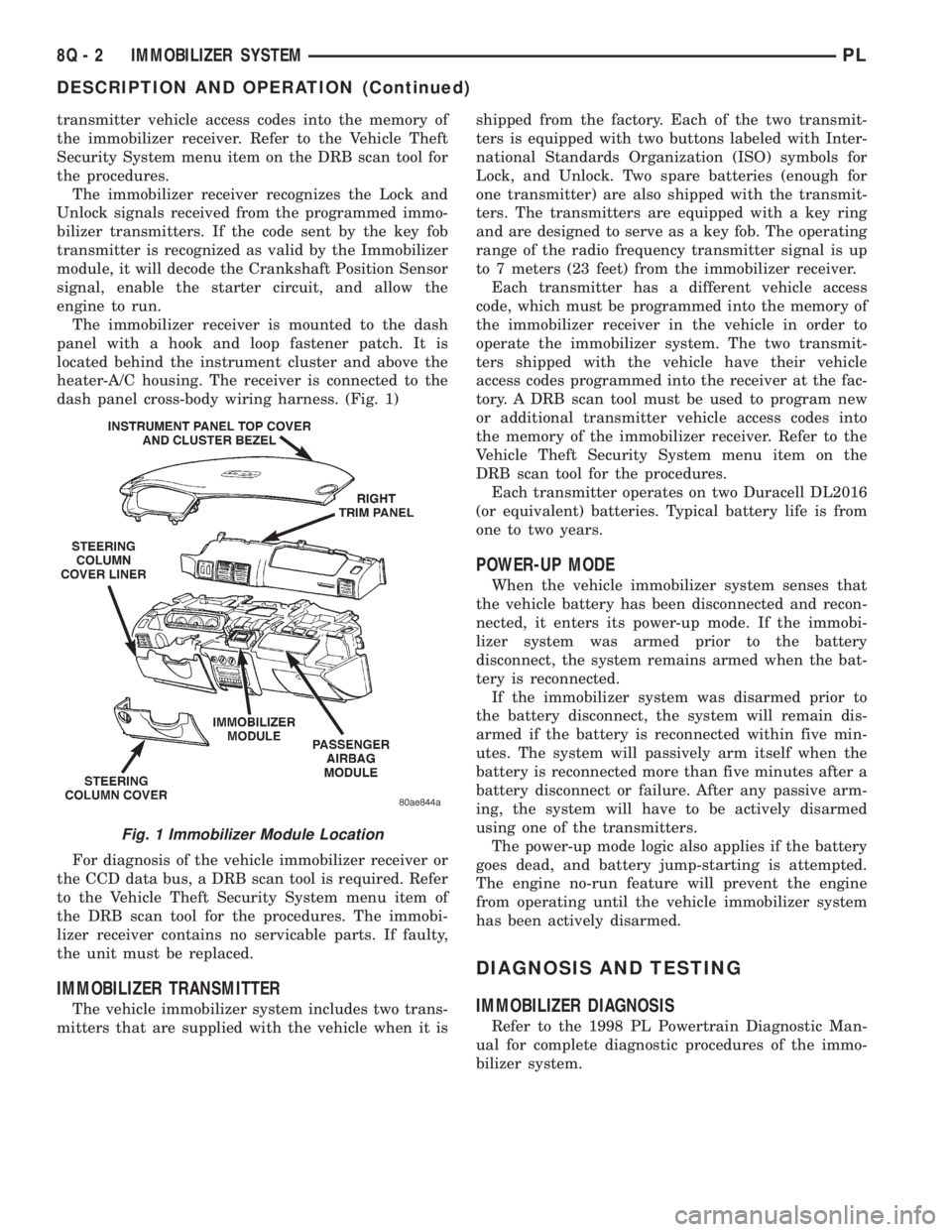
The immobilizer receiver is mounted to the dash
panel with a hook and loop fastener patch. It is
located behind the instrument cluster and above the
heater-A/C housing. The receiver is connected to the
dash panel cross-body wiring harness. (Fig. 1)
For diagnosis of the vehicle immobilizer receiver or
the CCD data bus, a DRB scan tool is required. Refer
to the Vehicle Theft Security System menu item of
the DRB scan tool for the procedures. The immobi-
lizer receiver contains no servicable parts. If faulty,
the unit must be replaced.
IMMOBILIZER TRANSMITTER
The vehicle immobilizer system includes two trans-
mitters that are supplied with the vehicle when it isshipped from the factory. Each of the two transmit-
ters is equipped with two buttons labeled with Inter-
national Standards Organization (ISO) symbols for
Lock, and Unlock. Two spare batteries (enough for
one transmitter) are also shipped with the transmit-
ters. The transmitters are equipped with a key ring
and are designed to serve as a key fob. The operating
range of the radio frequency transmitter signal is up
to 7 meters (23 feet) from the immobilizer receiver.
Each transmitter has a different vehicle access
code, which must be programmed into the memory of
the immobilizer receiver in the vehicle in order to
operate the immobilizer system. The two transmit-
ters shipped with the vehicle have their vehicle
access codes programmed into the receiver at the fac-
tory. A DRB scan tool must be used to program new
or additional transmitter vehicle access codes into
the memory of the immobilizer receiver. Refer to the
Vehicle Theft Security System menu item on the
DRB scan tool for the procedures.
Each transmitter operates on two Duracell DL2016
(or equivalent) batteries. Typical battery life is from
one to two years.
POWER-UP MODE
When the vehicle immobilizer system senses that
the vehicle battery has been disconnected and recon-
nected, it enters its power-up mode. If the immobi-
lizer system was armed prior to the battery
disconnect, the system remains armed when the bat-
tery is reconnected.
If the immobilizer system was disarmed prior to
the battery disconnect, the system will remain dis-
armed if the battery is reconnected within five min-
utes. The system will passively arm itself when the
battery is reconnected more than five minutes after a
battery disconnect or failure. After any passive arm-
ing, the system will have to be actively disarmed
using one of the transmitters.
The power-up mode logic also applies if the battery
goes dead, and battery jump-starting is attempted.
The engine no-run feature will prevent the engine
from operating until the vehicle immobilizer system
has been actively disarmed.
DIAGNOSIS AND TESTING
IMMOBILIZER DIAGNOSIS
Refer to the 1998 PL Powertrain Diagnostic Man-
ual for complete diagnostic procedures of the immo-
bilizer system.
Fig. 1 Immobilizer Module Location
8Q - 2 IMMOBILIZER SYSTEMPL
DESCRIPTION AND OPERATION (Continued)
Page 888 of 1200
(7) Attach the other end of the jumper wire to
relay terminal 86. This activates the relay. The ohm-
meter should now show continuity between relay ter-
minals 87 and 30. The ohmmeter should not show
continuity between relay terminals 87A and 30.
(8) Disconnect jumper wires.
(9) Replace the relay if it did not pass the continu-
ity and resistance tests. If the relay passed the tests,
it operates properly. Check the remainder of the ASD
and fuel pump relay circuits. Refer to group 8W, Wir-
ing Diagrams.
CAMSHAFT AND CRANKSHAFT POSITION SENSOR
Refer to Group 8D, Ignition for Diagnosis and Test-
ing of Camshaft and Crankshaft Sensors.
ENGINE COOLANT TEMPERATURE SENSOR
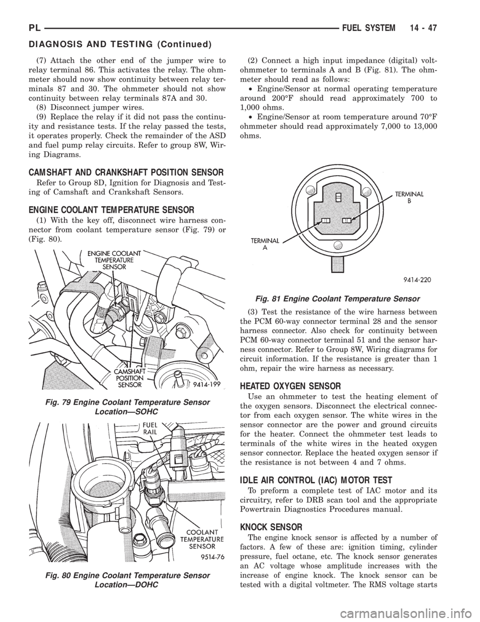
(1) With the key off, disconnect wire harness con-
nector from coolant temperature sensor (Fig. 79) or
(Fig. 80).(2) Connect a high input impedance (digital) volt-
ohmmeter to terminals A and B (Fig. 81). The ohm-
meter should read as follows:
²Engine/Sensor at normal operating temperature
around 200ÉF should read approximately 700 to
1,000 ohms.
²Engine/Sensor at room temperature around 70ÉF
ohmmeter should read approximately 7,000 to 13,000
ohms.
(3) T
est the resistance of the wire harness between
the PCM 60-way connector terminal 28 and the sensor
harness connector. Also check for continuity between
PCM 60-way connector terminal 51 and the sensor har-
ness connector. Refer to Group 8W, Wiring diagrams for
circuit information. If the resistance is greater than 1
ohm, repair the wire harness as necessary.
HEATED OXYGEN SENSOR
Use an ohmmeter to test the heating element of
the oxygen sensors. Disconnect the electrical connec-
tor from each oxygen sensor. The white wires in the
sensor connector are the power and ground circuits
for the heater. Connect the ohmmeter test leads to
terminals of the white wires in the heated oxygen
sensor connector. Replace the heated oxygen sensor if
the resistance is not between 4 and 7 ohms.
IDLE AIR CONTROL (IAC) MOTOR TEST
To preform a complete test of IAC motor and its
circuitry, refer to DRB scan tool and the appropriate
Powertrain Diagnostics Procedures manual.
KNOCK SENSOR
The engine knock sensor is affected by a number of
factors. A few of these are: ignition timing, cylinder
pressure, fuel octane, etc. The knock sensor generates
an AC voltage whose amplitude increases with the
increase of engine knock. The knock sensor can be
tested with a digital voltmeter. The RMS voltage starts
Fig. 79 Engine Coolant Temperature Sensor
LocationÐSOHC
Fig. 80 Engine Coolant Temperature Sensor
LocationÐDOHC
Fig. 81 Engine Coolant Temperature Sensor
PLFUEL SYSTEM 14 - 47
DIAGNOSIS AND TESTING (Continued)
Page 1079 of 1200
REMOVAL AND INSTALLATION
WHEEL COVER (LOCK-ON)
REMOVE
NOTE: When unthreading the wheel cover retaining
nuts (Fig. 11) from the wheel nuts it is recom-
mended that a hand wrench be used and not an
impact wrench. Use of an impact wrench could
result in damage to the lock-on wheel cover retain-
ing nuts.
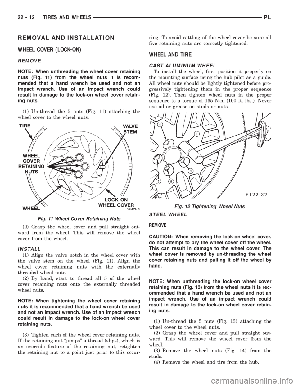
(1) Un-thread the 5 nuts (Fig. 11) attaching the
wheel cover to the wheel nuts.
(2) Grasp the wheel cover and pull straight out-
ward from the wheel. This will remove the wheel
cover from the wheel.
INSTALL
(1) Align the valve notch in the wheel cover with
the valve stem on the wheel (Fig. 11). Align the
wheel cover retaining nuts with the externally
threaded wheel nuts.
(2) By hand, start to thread all 5 of the wheel
cover retaining nuts onto the externally threaded
wheel nuts.
NOTE: When tightening the wheel cover retaining
nuts it is recommended that a hand wrench be used
and not an impact wrench. Use of an impact wrench
could result in damage to the lock-on wheel cover
retaining nuts.
(3) Tighten each of the wheel cover retaining nuts.
If the retaining nut ªjumpsº a thread (slips), which is
an override feature of the retaining nut, retighten
the retaining nut to a point just prior to this occur-ring. To avoid rattling of the wheel cover be sure all
five retaining nuts are correctly tightened.
WHEEL AND TIRE
CAST ALUMINUM WHEEL
To install the wheel, first position it properly on
the mounting surface using the hub pilot as a guide.
All wheel nuts should be lightly tightened before pro-
gressively tightening them in the proper sequence
(Fig. 12). Then tighten wheel nuts in the proper
sequence to a torque of 135 N´m (100 ft. lbs.). Never
use oil or grease on studs or nuts.
STEEL WHEEL
REMOVE
CAUTION: When removing the lock-on wheel cover,
do not attempt to pry the wheel cover off the wheel.
This can result in damage to the wheel cover. The
wheel cover is removed by un-threading the wheel
cover retaining nuts and pulling it off the wheel by
hand.
NOTE: When unthreading the lock-on wheel cover
retaining nuts (Fig. 13) from the wheel nuts it is rec-
ommended that a hand wrench be used and not an
impact wrench. Use of an impact wrench could
result in damage to the lock-on wheel cover retain-
ing nuts.
(1) Un-thread the 5 nuts (Fig. 13) attaching the
wheel cover to the wheel nuts.
(2) Grasp the wheel cover and pull straight out-
ward. This will remove the wheel cover from the
wheel.
(3) Remove the wheel nuts (Fig. 14) from the
studs.
(4) Remove the wheel and tire from the hub.
Fig. 11 Wheel Cover Retaining Nuts
Fig. 12 Tightening Wheel Nuts
22 - 12 TIRES AND WHEELSPL
Page 1080 of 1200
INSTALL
(1) To install the wheel, first position it properly
on the studs and hub mounting surface using the
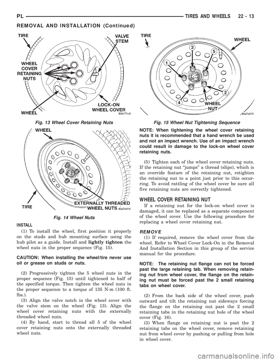
hub pilot as a guide. Install andlightly tightenthe
wheel nuts in the proper sequence (Fig. 15).
CAUTION: When installing the wheel/tire never use
oil or grease on studs or nuts.
(2) Progressively tighten the 5 wheel nuts in the
proper sequence (Fig. 15) until tightened to half of
the specified torque. Then tighten the wheel nuts in
the proper sequence to a torque of 135 N´m (100 ft.
lbs.).
(3) Align the valve notch in the wheel cover with
the valve stem on the wheel (Fig. 13). Align the
wheel cover retaining nuts with the externally
threaded wheel nuts.
(4) By hand, start to thread all 5 of the wheel
cover retaining nuts onto the externally threaded
wheel nuts.NOTE: When tightening the wheel cover retaining
nuts it is recommended that a hand wrench be used
and not an impact wrench. Use of an impact wrench
could result in damage to the lock-on wheel cover
retaining nuts.
(5) Tighten each of the wheel cover retaining nuts.
If the retaining nut ªjumpsº a thread (slips), which is
an override feature of the retaining nut, retighten
the retaining nut to a point just prior to this occur-
ring. To avoid rattling of the wheel cover be sure all
five retaining nuts are correctly tightened.
WHEEL COVER RETAINING NUT
If a retaining nut for the lock-on wheel cover is
damaged, it can be replaced as a separate component
of the wheel cover. Use the following procedure for
replacing a wheel cover retaining nut.
REMOVE
(1) If required, remove the wheel cover from the
wheel. Refer to Wheel Cover Lock-On in the Removal
And Installation Section in this group of the service
manual for the procedure.
NOTE: The retaining nut flange can not be forced
past the large retaining tab. When removing retain-
ing nut from wheel cover, the flange on the retain-
ing nut must be forced past the 2 small retaining
tabs on wheel cover.
(2) From the back side of the wheel cover, push
outward and tilt the retaining nut sideways forcing
the flange on the retaining nut past the 2 small
retaining tabs in the retaining nut hole of the wheel
cover (Fig. 16).
(3) When flange on retaining nut is past the 2
retaining tabs on the wheel cover, remove retaining
nut from wheel cover by pushing or pulling from hole
in wheel cover.
Fig. 13 Wheel Cover Retaining Nuts
Fig. 14 Wheel Nuts
Fig. 15 Wheel Nut Tightening Sequence
PLTIRES AND WHEELS 22 - 13
REMOVAL AND INSTALLATION (Continued)
Page 1140 of 1200
perature in test room and on vehicle must be 21É C
(70ÉF) minimum for this test.
NOTE: When connecting the service equipment
coupling to the line fitting, verify that the valve of
the coupling is fully closed. This will reduce the
amount of effort required to make the connection.
(1) Connect a tachometer and manifold gauge set.
(2) Set control to A/C, RECIRC, and PANEL, tem-
perature lever on full cool and blower on high.
(3) Start engine and hold at 1000 rpm with A/C
clutch engaged.
(4) Engine should be warmed up with doors and
windows closed.
(5) Insert a thermometer in the left center A/C
outlet and operate the engine for five minutes. The
A/C clutch may cycle depending on ambient condi-
tions.
(6) With the A/C clutch engaged, compare the dis-
charge air temperature to the A/C Performance Tem-
peratures Table.
(7) If the discharge air temperature fails to meet
the specifications in the performance temperature
chart. Refer to the Refrigerant Service Procedures for
further diagnosis.
COMPRESSOR NOISE DIAGNOSIS
Excessive noise while the A/C is being used, can be
caused by loose mounts, loose clutch, or high operat-
ing pressure. Verify compressor drive belt condition,
proper refrigerant charge and head pressure before
compressor repair is performed.
If the A/C drive belt slips at initial start-up, it does
not necessarily mean the compressor has failed.
With the close tolerances of a compressor it is pos-
sible to experience a temporary lockup. The longer
the A/C system is inactive, the more likely the condi-
tion to occur.
This condition is the result of normal refrigerant
movement within the A/C system caused by temper-
ature changes. The refrigerant movement may wash
the oil out of the compressor.
EXPANSION VALVE
NOTE: Expansion valve tests should be performed
after compressor tests.
Liquid CO2 is required to test the expansion
valve. It is available from most welding supply facil-
ities. CO2 is also available from companies which
service and sell fire extinguishers.
Review Safety Precautions and Warnings in the
General Information section of this Group. The work
area and vehicle must be 21É to 27ÉC (70É to 85ÉF)
when testing expansion valve. To test the expansion
valve:
(1) Connect a charging station or manifold gauge
set to the refrigerant system service ports.
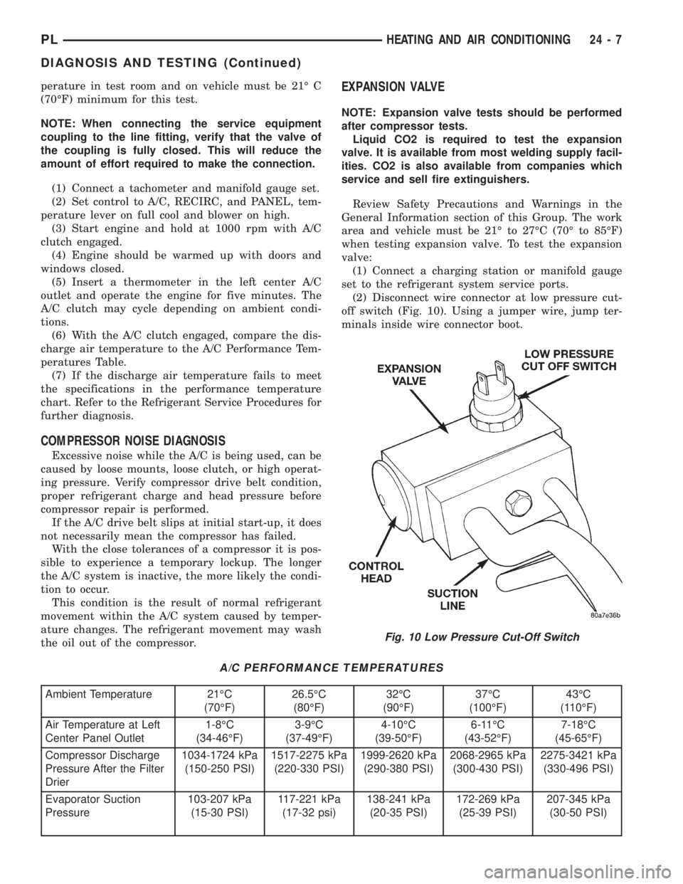
(2) Disconnect wire connector at low pressure cut-
off switch (Fig. 10). Using a jumper wire, jump ter-
minals inside wire connector boot.
A/C PERFORMANCE TEMPERATURES
Ambient Temperature 21ÉC
(70ÉF)26.5ÉC
(80ÉF)32ÉC
(90ÉF)37ÉC
(100ÉF)43ÉC
(110ÉF)
Air Temperature at Left
Center Panel Outlet1-8ÉC
(34-46ÉF)3-9ÉC
(37-49ÉF)4-10ÉC
(39-50ÉF)6-11ÉC
(43-52ÉF)7-18ÉC
(45-65ÉF)
Compressor Discharge
Pressure After the Filter
Drier1034-1724 kPa
(150-250 PSI)1517-2275 kPa
(220-330 PSI)1999-2620 kPa
(290-380 PSI)2068-2965 kPa
(300-430 PSI)2275-3421 kPa
(330-496 PSI)
Evaporator Suction
Pressure103-207 kPa
(15-30 PSI)117-221 kPa
(17-32 psi)138-241 kPa
(20-35 PSI)172-269 kPa
(25-39 PSI)207-345 kPa
(30-50 PSI)
Fig. 10 Low Pressure Cut-Off Switch
PLHEATING AND AIR CONDITIONING 24 - 7
DIAGNOSIS AND TESTING (Continued)
Page 1141 of 1200
(3) Close all doors, windows and vents to the pas-
senger compartment.
(4) Set Heater-A/C control to A/C, full heat, floor,
RECIRC. and high blower.
(5) Start the engine and hold the idle speed (1000
rpm). After the engine has reached running temper-
ature, allow the passenger compartment to heat up.
This will create the need for maximum refrigerant
flow into the evaporator.
(6) If the refrigerant charge is sufficient, discharge
(high pressure) gauge should read 965 to 2620 kPa
(140 to 380 psi). Suction (low pressure) gauge should
read 103 to 2417 kPa (15 to 35 psi). If system cannot
achieve proper pressure readings, replace the expan-
sion valve. If pressure is correct, proceed with test.
WARNING: PROTECT SKIN AND EYES FROM CON-
TACTING CO2 PERSONAL INJURY CAN RESULT.
(7) If suction side low pressure is within specified
range, freeze the expansion valve control head (Fig.
10) for 30 seconds. Use a super cold substance (liquid
CO2).Do not spray refrigerant on the expansion
valve for this test.Suction side low pressure should
drop to 34.5 kPa (5 psi) If not, replace expansion
valve.
(8) Allow expansion valve to thaw. The low pres-
sure gauge reading should stabilize at 103 to 241
kPa (15 to 35 psi). If not, replace expansion valve.
(9) When expansion valve test is complete, test
A/C overall performance. Refer to the Heater and A/C
Performance Test in this section. Remove all test
equipment before returning vehicle to use.
BLOWER MOTOR ELECTRICAL DIAGNOSIS
Refer to the Blower Motor Electrical System Diag-
nosis chart in this section. Also refer to Group 8W,
Wiring Diagrams for more information.
BLOWER MOTOR VIBRATION AND/OR NOISE
DIAGNOSIS
The resistor block supplies the blower motor with
varied voltage (low and middle speeds) or battery
voltage (high speed).
CAUTION: Stay clear of the blower motor and resis-
tor block (Hot). Do not operate the blower motor
with the resistor block removed from the heater-A/C
housing.
Refer to the Blower Motor Vibration/Noise chart
for diagnosis.
EVAPORATOR PROBE TEST
The work area and vehicle must be between 16É C
(60É F) and 32É C (90É F) when testing the switch.(1) Disconnect the three wire connector from the
evaporator probe lead located behind the glove box.
(2) Start engine and set A/C to low blower motor
speed, panel, full cool, and RECIRC.
(3) Using a voltmeter, check for battery voltage
between Pin 1 and 2. If no voltage is detected, there
is no power to the switch. Check wiring and fuses.
Refer to Group 8W, Wiring Diagrams for circuit diag-
nosis.
(4) Using a voltmeter, check for battery voltage
between Pin 1 and Pin 3. If no voltage is detected,
there is no voltage from the Powertrain Control Mod-
ule. Refer to Group 8W, Wiring Diagrams. If voltage
is OK, connect a jumper wire between Pin 1 and Pin
3. The compressor clutch should engage. If the clutch
engages, remove the jumper wire immediately and go
to Step 5. If the compressor clutch does not engage,
check the operation of the clutch and repair as nec-
essary.
(5) If compressor clutch engages, connect the evap-
orator probe 3-way connector. The compressor clutch
should engage or cycle depending on evaporator tem-
perature. If OK, go to Step 6. If not OK, replace the
clutch cycling switch.
(6) The engine running and the A/C set to:
²Blower motor on low speed
²Panel position
²Full cool
²RECIRC.
Close all doors and windows. Place a thermometer
in the center discharge vent.
(7) If the clutch does not begin to cycle off between
2É C to 7É C (35É F to 45É F), verify that the evapo-
rator probe is fully installed and not loose in evapo-
rator. If it is not properly installed, install probe and
retest outlet temperature. If the evaporator probe is
properly installed, replace the clutch cycling switch.
HEATER PERFORMANCE TEST
PRE-DIAGNOSTIC PREPARATIONS
Review Safety Precautions and Warnings in this
group before performing the following procedures.
Check the coolant level, drive belt tension, vacuum
line connections, radiator air flow and fan operation.
Start engine and allow to warm up to normal tem-
perature.
WARNING: DO NOT REMOVE RADIATOR CAP
WHEN ENGINE IS HOT, PERSONAL INJURY CAN
RESULT.
If vehicle has been run recently, wait 15 minutes
before removing cap. Place a rag over the cap and
turn it to the first safety stop. Allow pressure to
escape through the overflow tube. When the system
stabilizes, remove the cap completely.
24 - 8 HEATING AND AIR CONDITIONINGPL
DIAGNOSIS AND TESTING (Continued)