air condition DODGE NEON 1999 Service Repair Manual
[x] Cancel search | Manufacturer: DODGE, Model Year: 1999, Model line: NEON, Model: DODGE NEON 1999Pages: 1200, PDF Size: 35.29 MB
Page 5 of 1200
²Replace air cleaner element.
²Replace spark plugs.
²Change automatic transmission fluid.
37,500 Miles (60 000 km) or at 30 months
²Change engine oil.
45,000 Miles (72 000 km) or at 36 months
²Change engine oil.
²Replace engine oil filter.
²Inspect front brake pads and rear brake linings.
²Adjust drive belt tension.
²Flush and replace engine coolant at 36 months,
regardless of mileage.
52,500 Miles (84 000 km) or at 42 months
²Change engine oil.
²Flush and replace engine coolant if not done at
36 months.
60,000 Miles (96 000 km) or at 48 months
²Change engine oil.
²Replace engine oil filter.
²Check and replace, if necessary***, the PCV
valve.**
²Lubricate front suspension upper ball joints.
²Replace drive belts.
²Replace air cleaner element.
²Replace ignition cables.
²Replace spark plugs.
²Change automatic transmission fluid.
67,500 Miles (108 000 km) or at 54 months
²Change engine oil.
²Inspect front brake pads and rear brake linings.
75,000 Miles (120 000 km) or at 60 months
²Change engine oil.
²Replace engine oil filter.
²Adjust drive belt tension.
²Flush and replace engine coolant if it has been
30,000 miles (48 000 km) or 24 months since last
change.
82,500 Miles (132 000 km) or at 66 months
²Change engine oil.
²Flush and replace engine coolant if it has been
30,000 miles (48 000 km) or 24 months since last
change.
90,000 Miles (144 000 km) or at 72 months
²Change engine oil.
²Replace engine oil filter.
²Check and replace, if necessary***, the PCV
valve.**
²Lubricate front suspension upper ball joints.
²Inspect front brake pads and rear brake linings.²Adjust drive belt tension.
²Replace air cleaner air cleaner element.
²Replace spark plugs.
²Change automatic transmission fluid.
97,500 Miles (156 000 km) or at 78 months
²Change engine oil.
105,000 Miles (168 000 km)
²Change engine oil.
²Replace engine oil filter.
²Replace engine timing belt
²Adjust drive belt tension.
SCHEDULE ± B
NOTE: * Follow this schedule if you usually operate
your vehicle under one or more of the following
conditions. Change the automatic transmission
fluid and filter every 15,000 miles (24 000 km) if you
usually operate your vehicle under one of the con-
ditions marked with an *.
3,000 Miles (5 000 km)
²Change engine oil
6,000 Miles (10 000 km)
²Change engine oil
²Replace engine oil filter.
9,000 Miles (14 000 km)
²Change engine oil
²Inspect front brake pads and rear brake lining.
12,000 Miles (19 000 km)
²Change engine oil
²Replace engine oil filter.
15,000 Miles (24 000 km)
²Change engine oil
²Adjust drive belt tension.
²Inspect and replace, if required, the air
cleaner element.
²Change automatic transaxle fluid and filter.
Adjust the bands.*
18,000 Miles (29 000 km)
²Change engine oil
²Replace engine oil filter.
²Inspect front brake pads and rear brake linings.
21,000 Miles (34 000 km)
²Change engine oil
0 - 4 LUBRICATION AND MAINTENANCEPL
GENERAL INFORMATION (Continued)
Page 9 of 1200
DISCONNECT CABLE CLAMPS AS FOLLOWS:
²Disconnect BLACK cable clamp from engine
ground on disabled vehicle.
²When using a Booster vehicle, disconnect
BLACK cable clamp from battery negative terminal.
Disconnect RED cable clamp from battery positive
terminal.
²Disconnect RED cable clamp from battery posi-
tive terminal on disabled vehicle.
TOWING RECOMMENDATIONS
WARNING: DO NOT ALLOW TOWING ATTACH-
MENT DEVICES TO CONTACT THE FUEL TANK OR
LINES, FUEL LEAK CAN RESULT. DO NOT LIFT OR
TOW VEHICLE BY FRONT OR REAR BUMPER, OR
BUMPER ENERGY ABSORBER UNITS. DO NOT
VENTURE UNDER A LIFTED VEHICLE IF NOT SUP-
PORTED PROPERLY ON SAFETY STANDS. DO NOT
ALLOW PASSENGERS TO RIDE IN A TOWED VEHI-
CLE. USE A SAFETY CHAIN THAT IS INDEPENDENT
FROM THE TOWING ATTACHMENT DEVICE.
CAUTION: Do not damage brake lines, exhaust
system, shock absorbers, sway bars, or any other
under vehicle components when attaching towing
device to vehicle. Do not attach towing device to
front or rear suspension components. Do not
secure vehicle to towing device by the use of front
or rear suspension or steering components.
Remove or secure loose or protruding objects from
a damaged vehicle before towing. Refer to state and
local rules and regulations before towing a vehicle.
Do not allow weight of towed vehicle to bear on
lower fascia, air dams, or spoilers.
RECOMMENDED TOWING EQUIPMENT
To avoid damage to bumper fascia and air dams
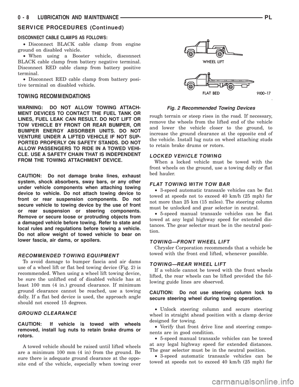
use of a wheel lift or flat bed towing device (Fig. 2) is
recommended. When using a wheel lift towing device,
be sure the unlifted end of disabled vehicle has at
least 100 mm (4 in.) ground clearance. If minimum
ground clearance cannot be reached, use a towing
dolly. If a flat bed device is used, the approach angle
should not exceed 15 degrees.
GROUND CLEARANCE
CAUTION: If vehicle is towed with wheels
removed, install lug nuts to retain brake drums or
rotors.
A towed vehicle should be raised until lifted wheels
are a minimum 100 mm (4 in) from the ground. Be
sure there is adequate ground clearance at the oppo-
site end of the vehicle, especially when towing overrough terrain or steep rises in the road. If necessary,
remove the wheels from the lifted end of the vehicle
and lower the vehicle closer to the ground, to
increase the ground clearance at the opposite end of
the vehicle. Install lug nuts on wheel attaching studs
to retain brake drums or rotors.
LOCKED VEHICLE TOWING
When a locked vehicle must be towed with the
front wheels on the ground, use a towing dolly or flat
bed hauler.
FLAT TOWING WITH TOW BAR
²3-speed automatic transaxle vehicles can be flat
towed at speeds not to exceed 40 km/h (25 mph) for
not more than 25 km (15 miles). The steering column
must be unlocked and gear selector in neutral.
²5-speed manual transaxle vehicles can be flat
towed at any legal highway speed for extended dis-
tances. The gear selector must be in the neutral posi-
tion.
TOWINGÐFRONT WHEEL LIFT
Chrysler Corporation recommends that a vehicle be
towed with the front end lifted, whenever possible.
TOWINGÐREAR WHEEL LIFT
If a vehicle cannot be towed with the front wheels
lifted, the rear wheels can be lifted provided the fol-
lowing guide lines are observed.
CAUTION: Do not use steering column lock to
secure steering wheel during towing operation.
²Unlock steering column and secure steering
wheel in straight ahead position with a clamp device
designed for towing.
²Verify that front drive line and steering compo-
nents are in good condition.
²5-speed manual transaxle vehicles can be towed
at any legal highway speed for extended distances.
The gear selector must be in the neutral position.
²3-speed automatic transaxle vehicles can be
towed at speeds not to exceed 40 km/h (25 mph) for
Fig. 2 Recommended Towing Devices
0 - 8 LUBRICATION AND MAINTENANCEPL
SERVICE PROCEDURES (Continued)
Page 16 of 1200
PRE-ALIGNMENT VEHICLE INSPECTION
CAUTION: If the front suspension crossmember
shows any sign of impact damage, the steering col-
umn to steering gear coupling must be inspected.
Refer to Group 19 Steering in this service manual
for the inspection procedure.
Before any attempt is made to change or correct
the wheel alignment factors, the following inspection
and necessary corrections must be made on those
parts which influence the steering of the vehicle.
(1) Be sure the fuel tank is full when the wheel
alignment specifications are checked and or adjusted.
A full tank of fuel weighs approximately 75 pounds,
if the fuel tank is not full this reduction in weight
will affect the curb height of the vehicle and the
alignment specifications.
(2) Alignment specifications of a vehicle can be the
most accurately checked and set when the passenger
compartment and trunk of the vehicle are vacant
with the exception of the spare tire. People, luggage,
and any other appreciable weight will adversely
affect the checking and setting of the camber specifi-
cation.
(3) Check and if required, inflate all of the tires to
the recommended air pressure. All tires must be of
the same size and in good condition and have approx-
imately the same tread wear.Note the type of
tread wear on the tire, this will aid in diagnos-
ing problems. Refer to Group 22 Tires And
Wheels in this service manual for the tire wear
diagnosis.
(4) Check the front tire and wheel assemblies for
radial runout.
(5) Before beginning the alignment process,
inspect all suspension component fasteners for loose-
ness and/or loss of specified torque.
(6) Inspect the lower front ball joints and all steer-
ing linkage for looseness and any signs of wear and
or damage.
(7) Inspect the tie rod ends for looseness and any
signs of wear and or damage.
(8) Inspect the rubber bushings on all suspension
components for signs of wear or deterioration. If any
bushings show signs of wear or deterioration they
should be replaced prior to aligning the vehicle.
SERVICE PROCEDURES
WHEEL ALIGNMENT CHECK AND ADJUSTMENT
PROCEDURE
CASTER CAMBER
Front and rear Caster and Camber settings on this
vehicle are determined at the time the vehicle isdesigned, by the location of the vehicle's suspension
components. This is called a Net Build vehicle and
results in no required adjustment of Caster and
Camber after vehicle is built or when servicing the
suspension components. Thus Caster and Camber are
not normally considered an adjustable specification
when performing an alignment on this vehicle.
Though Caster and Camber are not adjustable they
must be checked to ensure they meet vehicle specifi-
cations.
If front and or rear camber is found not to meet
the vehicle alignment specifications, it can be
adjusted using a Mopar Service Kit developed to
allow for camber adjustment. If a vehicle's front or
rear camber is found to be outside the specifications,
the vehicles suspension components should be
inspected for any signs of damage on bending.This
must be done before using the Mopar Service
Kit for setting camber to meet required specifi-
cation.
If a vehicles caster is not within manufacturers
alignment specifications, check for damaged suspen-
sion components or body parts. This type of damage
can cause component locations to move affecting
vehicle alignment.No adjustment can be made
for the Caster setting on this vehicle.
CAUTION: Do not attempt to adjust the vehicles
Caster or Camber by heating, bending or any other
modification of the suspension components.
(1) Correctly position vehicle on alignment rack
and install all required equipment on vehicle, per the
alignment equipment manufacturers specifications.
(2) Center the steering wheel and lock in place
using a steering wheel clamp.
NOTE: Prior to reading each alignment specifica-
tion, jounce the front and rear of the vehicle an
equal number of times. Induce jounce (rear first
then front) by grasping center of bumper and jounc-
ing each end of vehicle an equal number of times.
Bumper should always be released when vehicle is
at the bottom of the jounce cycle.
(3) Correctly jounce vehicle and read front and
rear alignment settings and compare to vehicle spec-
ifications for Camber, Caster and Toe. See Alignment
Specifications in this group of the service manual for
required specifications.If front and rear camber
readings are within required specifications pro-
ceed to step Step 3 in the Front And Rear Toe
Setting procedure. If Camber readings are not
within specifications refer to step Step 1 in the
following camber adjustment bolt package
installation procedure, for the front and rear
Camber adjustment procedure.
PLSUSPENSION 2 - 5
DIAGNOSIS AND TESTING (Continued)
Page 54 of 1200
Inspect the tension strut for signs of contact with
the ground or road debris which has bent or caused
other damage to the tension strut. If the tension
strut is bent or damaged the tension strut will
require replacement.Do not attempt to repair or
straighten a tension strut.
STABILIZER BAR AND BUSHINGS
Inspect the stabilizer bar for damage or bending.
Inspect for broken or distorted stabilizer bar bush-
ings, bushing retainers, and worn or damaged stabi-
lizer bar to strut attaching links. If stabiizer bar to
rear frame rail bushing replacement is required,
bushings can be removed from sway bar by opening
slit and peeling bushing off sway bar.
STABILIZER BAR ATTACHING LINKS
Inspect the bushings and sleeves in the stabilizer
bar attaching links for damage or deterioration.
Inspect the stabilizer bar attaching link to ensure it
is not bent or broken. If any of these conditions are
present when inspecting the attaching links, replace-
ment of the attaching link is required.
SERVICE PROCEDURES
REAR WHEEL ALIGNMENT
Refer to Front And Rear Wheel Toe Setting Proce-
dures in the Wheel Alignment Check And Adjustment
section in this group of the service manual for the
required rear wheel Toe setting procedure.
REMOVAL AND INSTALLATION
STRUT ASSEMBLY
REMOVE
(1) Raise vehicle on jackstands or centered on a
frame contact type hoist. See Hoisting in the Lubri-
cation and Maintenance section of this manual, for
the required lifting procedure to be used for this
vehicle.
(2) Remove the rear wheel and tire assembly from
the vehicle.
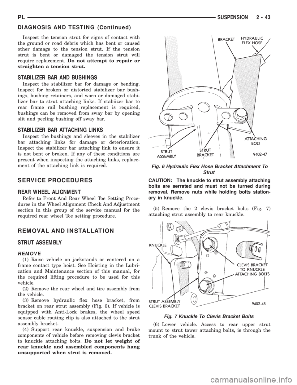
(3) Remove hydraulic flex hose bracket, from
bracket on rear strut assembly (Fig. 6). If vehicle is
equipped with Anti-Lock brakes, the wheel speed
sensor cable routing clip is also attached to the strut
assembly bracket.
(4) Support rear knuckle, suspension and brake
components of vehicle before removing clevis bracket
to knuckle attaching bolts.Do not let weight of
rear knuckle and assembled components hang
unsupported when strut is removed.CAUTION: The knuckle to strut assembly attaching
bolts are serrated and must not be turned during
removal. Remove nuts while holding bolts station-
ary in knuckle.
(5) Remove the 2 clevis bracket bolts (Fig. 7)
attaching strut assembly to rear knuckle.
(6) Lower vehicle. Access to rear upper strut
mount to strut tower attaching bolts, is through the
trunk of the vehicle.
Fig. 6 Hydraulic Flex Hose Bracket Attachment To
Strut
Fig. 7 Knuckle To Clevis Bracket Bolts
PLSUSPENSION 2 - 43
DIAGNOSIS AND TESTING (Continued)
Page 88 of 1200
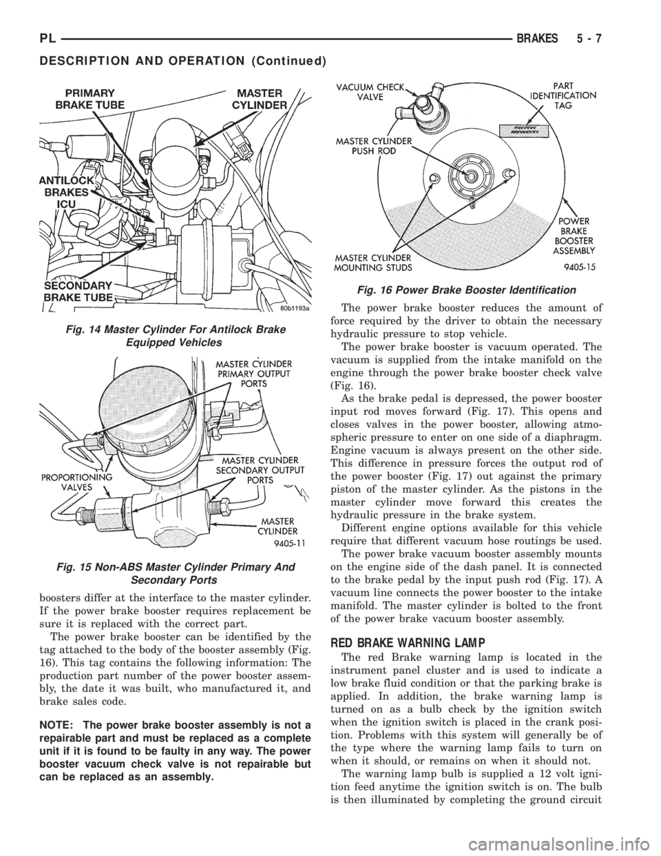
boosters differ at the interface to the master cylinder.
If the power brake booster requires replacement be
sure it is replaced with the correct part.
The power brake booster can be identified by the
tag attached to the body of the booster assembly (Fig.
16). This tag contains the following information: The
production part number of the power booster assem-
bly, the date it was built, who manufactured it, and
brake sales code.
NOTE: The power brake booster assembly is not a
repairable part and must be replaced as a complete
unit if it is found to be faulty in any way. The power
booster vacuum check valve is not repairable but
can be replaced as an assembly.The power brake booster reduces the amount of
force required by the driver to obtain the necessary
hydraulic pressure to stop vehicle.
The power brake booster is vacuum operated. The
vacuum is supplied from the intake manifold on the
engine through the power brake booster check valve
(Fig. 16).
As the brake pedal is depressed, the power booster
input rod moves forward (Fig. 17). This opens and
closes valves in the power booster, allowing atmo-
spheric pressure to enter on one side of a diaphragm.
Engine vacuum is always present on the other side.
This difference in pressure forces the output rod of
the power booster (Fig. 17) out against the primary
piston of the master cylinder. As the pistons in the
master cylinder move forward this creates the
hydraulic pressure in the brake system.
Different engine options available for this vehicle
require that different vacuum hose routings be used.
The power brake vacuum booster assembly mounts
on the engine side of the dash panel. It is connected
to the brake pedal by the input push rod (Fig. 17). A
vacuum line connects the power booster to the intake
manifold. The master cylinder is bolted to the front
of the power brake vacuum booster assembly.
RED BRAKE WARNING LAMP
The red Brake warning lamp is located in the
instrument panel cluster and is used to indicate a
low brake fluid condition or that the parking brake is
applied. In addition, the brake warning lamp is
turned on as a bulb check by the ignition switch
when the ignition switch is placed in the crank posi-
tion. Problems with this system will generally be of
the type where the warning lamp fails to turn on
when it should, or remains on when it should not.
The warning lamp bulb is supplied a 12 volt igni-
tion feed anytime the ignition switch is on. The bulb
is then illuminated by completing the ground circuit
Fig. 14 Master Cylinder For Antilock Brake
Equipped Vehicles
Fig. 15 Non-ABS Master Cylinder Primary And
Secondary Ports
Fig. 16 Power Brake Booster Identification
PLBRAKES 5 - 7
DESCRIPTION AND OPERATION (Continued)
Page 98 of 1200
(2) Remove hydraulic brake tube (Fig. 26) from
proportioning valve controlling the rear wheel of the
vehicle which has premature wheel skid.
(3) Remove proportioning valve from that outlet
port of the master cylinder.
CAUTION: Be sure the pressure test fitting being
installed into master cylinder, has the correct
thread sizes for installation into the master cylinder
and the installation of the proportioning valve.
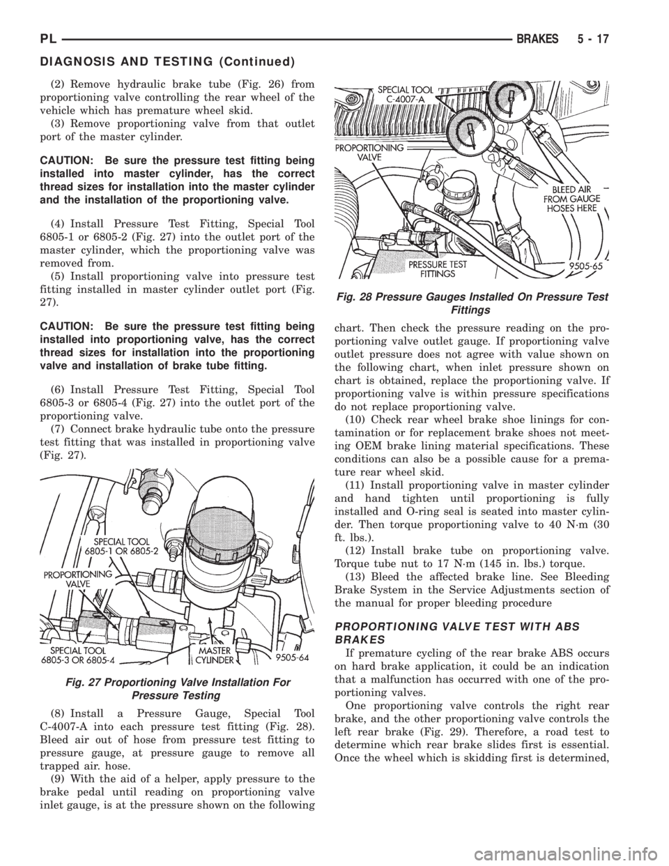
(4) Install Pressure Test Fitting, Special Tool
6805-1 or 6805-2 (Fig. 27) into the outlet port of the
master cylinder, which the proportioning valve was
removed from.
(5) Install proportioning valve into pressure test
fitting installed in master cylinder outlet port (Fig.
27).
CAUTION: Be sure the pressure test fitting being
installed into proportioning valve, has the correct
thread sizes for installation into the proportioning
valve and installation of brake tube fitting.
(6) Install Pressure Test Fitting, Special Tool
6805-3 or 6805-4 (Fig. 27) into the outlet port of the
proportioning valve.
(7) Connect brake hydraulic tube onto the pressure
test fitting that was installed in proportioning valve
(Fig. 27).
(8) Install a Pressure Gauge, Special Tool
C-4007-A into each pressure test fitting (Fig. 28).
Bleed air out of hose from pressure test fitting to
pressure gauge, at pressure gauge to remove all
trapped air. hose.
(9) With the aid of a helper, apply pressure to the
brake pedal until reading on proportioning valve
inlet gauge, is at the pressure shown on the followingchart. Then check the pressure reading on the pro-
portioning valve outlet gauge. If proportioning valve
outlet pressure does not agree with value shown on
the following chart, when inlet pressure shown on
chart is obtained, replace the proportioning valve. If
proportioning valve is within pressure specifications
do not replace proportioning valve.
(10) Check rear wheel brake shoe linings for con-
tamination or for replacement brake shoes not meet-
ing OEM brake lining material specifications. These
conditions can also be a possible cause for a prema-
ture rear wheel skid.
(11) Install proportioning valve in master cylinder
and hand tighten until proportioning is fully
installed and O-ring seal is seated into master cylin-
der. Then torque proportioning valve to 40 N´m (30
ft. lbs.).
(12) Install brake tube on proportioning valve.
Torque tube nut to 17 N´m (145 in. lbs.) torque.
(13) Bleed the affected brake line. See Bleeding
Brake System in the Service Adjustments section of
the manual for proper bleeding procedure
PROPORTIONING VALVE TEST WITH ABS
BRAKES
If premature cycling of the rear brake ABS occurs
on hard brake application, it could be an indication
that a malfunction has occurred with one of the pro-
portioning valves.
One proportioning valve controls the right rear
brake, and the other proportioning valve controls the
left rear brake (Fig. 29). Therefore, a road test to
determine which rear brake slides first is essential.
Once the wheel which is skidding first is determined,
Fig. 27 Proportioning Valve Installation For
Pressure Testing
Fig. 28 Pressure Gauges Installed On Pressure Test
Fittings
PLBRAKES 5 - 17
DIAGNOSIS AND TESTING (Continued)
Page 141 of 1200
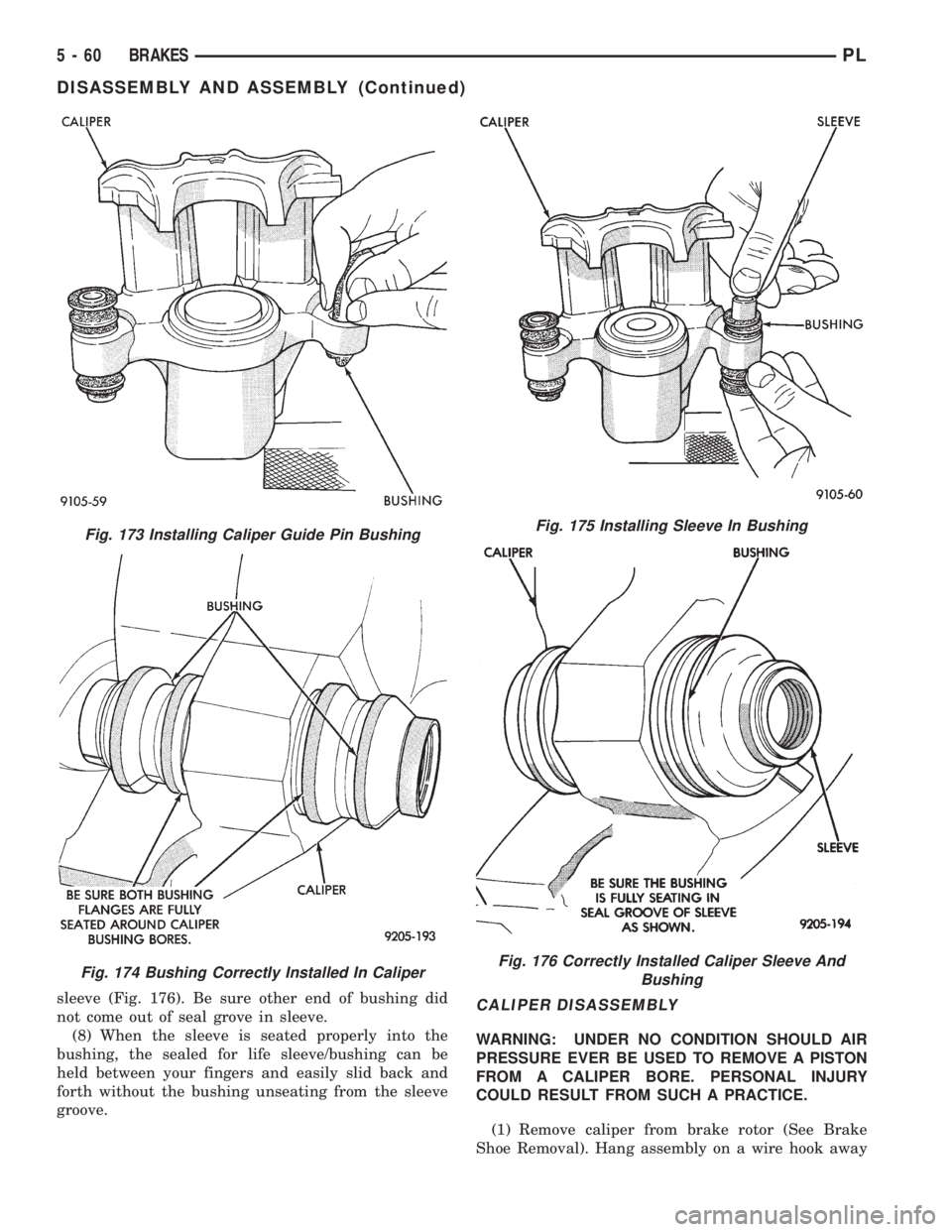
sleeve (Fig. 176). Be sure other end of bushing did
not come out of seal grove in sleeve.
(8) When the sleeve is seated properly into the
bushing, the sealed for life sleeve/bushing can be
held between your fingers and easily slid back and
forth without the bushing unseating from the sleeve
groove.CALIPER DISASSEMBLY
WARNING: UNDER NO CONDITION SHOULD AIR
PRESSURE EVER BE USED TO REMOVE A PISTON
FROM A CALIPER BORE. PERSONAL INJURY
COULD RESULT FROM SUCH A PRACTICE.
(1) Remove caliper from brake rotor (See Brake
Shoe Removal). Hang assembly on a wire hook away
Fig. 173 Installing Caliper Guide Pin Bushing
Fig. 174 Bushing Correctly Installed In Caliper
Fig. 175 Installing Sleeve In Bushing
Fig. 176 Correctly Installed Caliper Sleeve And
Bushing
5 - 60 BRAKESPL
DISASSEMBLY AND ASSEMBLY (Continued)
Page 144 of 1200
MUST always be used when installing brake
hose to caliper.
(12) Bleed the brake system (see Bleeding Brake
System).
WHEEL CYLINDER (REAR DRUM BRAKE)
DISASSEMBLE
To disassemble the wheel cylinders, proceed as fol-
lows:
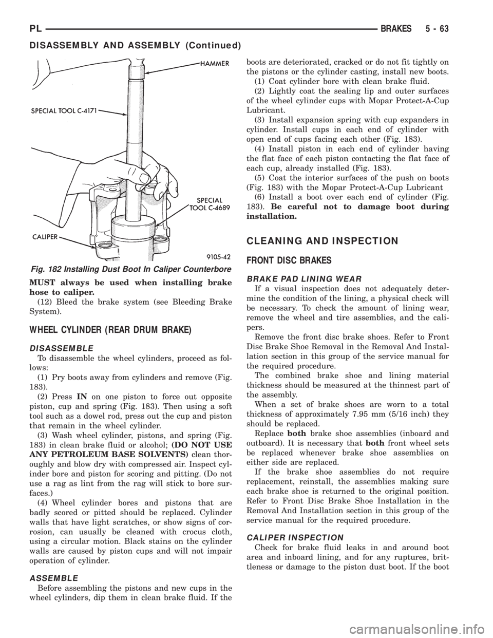
(1) Pry boots away from cylinders and remove (Fig.
183).
(2) PressINon one piston to force out opposite
piston, cup and spring (Fig. 183). Then using a soft
tool such as a dowel rod, press out the cup and piston
that remain in the wheel cylinder.
(3) Wash wheel cylinder, pistons, and spring (Fig.
183) in clean brake fluid or alcohol;(DO NOT USE
ANY PETROLEUM BASE SOLVENTS)clean thor-
oughly and blow dry with compressed air. Inspect cyl-
inder bore and piston for scoring and pitting. (Do not
use a rag as lint from the rag will stick to bore sur-
faces.)
(4) Wheel cylinder bores and pistons that are
badly scored or pitted should be replaced. Cylinder
walls that have light scratches, or show signs of cor-
rosion, can usually be cleaned with crocus cloth,
using a circular motion. Black stains on the cylinder
walls are caused by piston cups and will not impair
operation of cylinder.
ASSEMBLE
Before assembling the pistons and new cups in the
wheel cylinders, dip them in clean brake fluid. If theboots are deteriorated, cracked or do not fit tightly on
the pistons or the cylinder casting, install new boots.
(1) Coat cylinder bore with clean brake fluid.
(2) Lightly coat the sealing lip and outer surfaces
of the wheel cylinder cups with Mopar Protect-A-Cup
Lubricant.
(3) Install expansion spring with cup expanders in
cylinder. Install cups in each end of cylinder with
open end of cups facing each other (Fig. 183).
(4) Install piston in each end of cylinder having
the flat face of each piston contacting the flat face of
each cup, already installed (Fig. 183).
(5) Coat the interior surfaces of the push on boots
(Fig. 183) with the Mopar Protect-A-Cup Lubricant
(6) Install a boot over each end of cylinder (Fig.
183).Be careful not to damage boot during
installation.
CLEANING AND INSPECTION
FRONT DISC BRAKES
BRAKE PAD LINING WEAR
If a visual inspection does not adequately deter-
mine the condition of the lining, a physical check will
be necessary. To check the amount of lining wear,
remove the wheel and tire assemblies, and the cali-
pers.
Remove the front disc brake shoes. Refer to Front
Disc Brake Shoe Removal in the Removal And Instal-
lation section in this group of the service manual for
the required procedure.
The combined brake shoe and lining material
thickness should be measured at the thinnest part of
the assembly.
When a set of brake shoes are worn to a total
thickness of approximately 7.95 mm (5/16 inch) they
should be replaced.
Replacebothbrake shoe assemblies (inboard and
outboard). It is necessary thatbothfront wheel sets
be replaced whenever brake shoe assemblies on
either side are replaced.
If the brake shoe assemblies do not require
replacement, reinstall, the assemblies making sure
each brake shoe is returned to the original position.
Refer to Front Disc Brake Shoe Installation in the
Removal And Installation section in this group of the
service manual for the required procedure.
CALIPER INSPECTION
Check for brake fluid leaks in and around boot
area and inboard lining, and for any ruptures, brit-
tleness or damage to the piston dust boot. If the boot
Fig. 182 Installing Dust Boot In Caliper Counterbore
PLBRAKES 5 - 63
DISASSEMBLY AND ASSEMBLY (Continued)
Page 152 of 1200
PREMATURE ABS CYCLING
NOTE: When working on a vehicle which has a
complaint of premature ABS cycling it may be nec-
essary to use a DRB Scan Tool to detect and verify
the condition.
There is one complaint called Premature ABS
Cycling in which neither the Red Brake Warning
Lamp nor the Amber Antilock Lamp were illumi-
nated and no fault codes were stored in the CAB.
Symptoms of Premature ABS Cycling, include click-
ing sounds from the solenoids valves, pump motor
running and pulsations in the brake pedal. This con-
dition can occur at any braking rate of the vehicle
and on any type of road surface. This creates an
additional condition which needs to be correctly
assessed when diagnosing problems with the antilock
brake system.
The following conditions are common causes that
need to be checked when diagnosing a condition of
Premature ABS Cycling. Damaged tone wheels,
incorrect tone wheels, damage to a wheel speed sen-
sor mounting boss on a steering knuckle, a loose
wheel speed sensor mounting bolt, and excessive tone
wheel runout. Also, an excessively large tone wheel
to wheel speed sensor air gap can lead to the condi-
tion of Premature ABS Cycling. Special attention is
to be given to these components when diagnosing a
vehicle exhibiting the condition of Premature ABS
Cycling. After diagnosing the defective component,
repair or replace as required.
When the component repair or replacement is com-
pleted, test drive the vehicle to verify the condition of
Premature ABS Cycling has been corrected.
ABS BRAKE SYSTEM COMPONENTS
The following is a detailed description of the Teves
Mark 20 ABS brake system components. For infor-
mation on servicing the base brake system compo-
nents, see the base Brake System section of this
Service Manual.
ABS MASTER CYLINDER AND POWER BRAKE
BOOSTER
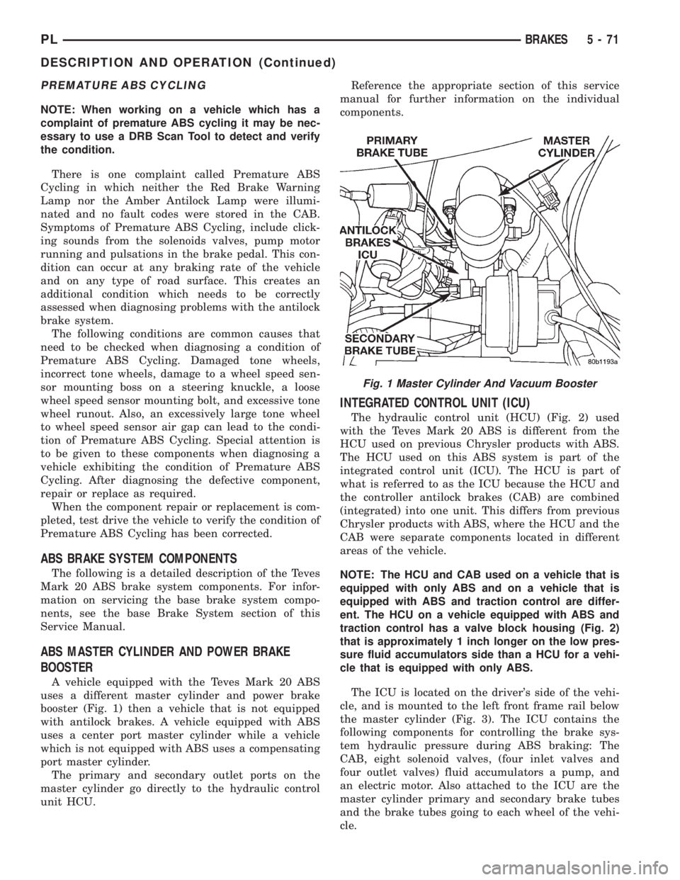
A vehicle equipped with the Teves Mark 20 ABS
uses a different master cylinder and power brake
booster (Fig. 1) then a vehicle that is not equipped
with antilock brakes. A vehicle equipped with ABS
uses a center port master cylinder while a vehicle
which is not equipped with ABS uses a compensating
port master cylinder.
The primary and secondary outlet ports on the
master cylinder go directly to the hydraulic control
unit HCU.Reference the appropriate section of this service
manual for further information on the individual
components.
INTEGRATED CONTROL UNIT (ICU)
The hydraulic control unit (HCU) (Fig. 2) used
with the Teves Mark 20 ABS is different from the
HCU used on previous Chrysler products with ABS.
The HCU used on this ABS system is part of the
integrated control unit (ICU). The HCU is part of
what is referred to as the ICU because the HCU and
the controller antilock brakes (CAB) are combined
(integrated) into one unit. This differs from previous
Chrysler products with ABS, where the HCU and the
CAB were separate components located in different
areas of the vehicle.
NOTE: The HCU and CAB used on a vehicle that is
equipped with only ABS and on a vehicle that is
equipped with ABS and traction control are differ-
ent. The HCU on a vehicle equipped with ABS and
traction control has a valve block housing (Fig. 2)
that is approximately 1 inch longer on the low pres-
sure fluid accumulators side than a HCU for a vehi-
cle that is equipped with only ABS.
The ICU is located on the driver's side of the vehi-
cle, and is mounted to the left front frame rail below
the master cylinder (Fig. 3). The ICU contains the
following components for controlling the brake sys-
tem hydraulic pressure during ABS braking: The
CAB, eight solenoid valves, (four inlet valves and
four outlet valves) fluid accumulators a pump, and
an electric motor. Also attached to the ICU are the
master cylinder primary and secondary brake tubes
and the brake tubes going to each wheel of the vehi-
cle.
Fig. 1 Master Cylinder And Vacuum Booster
PLBRAKES 5 - 71
DESCRIPTION AND OPERATION (Continued)
Page 188 of 1200
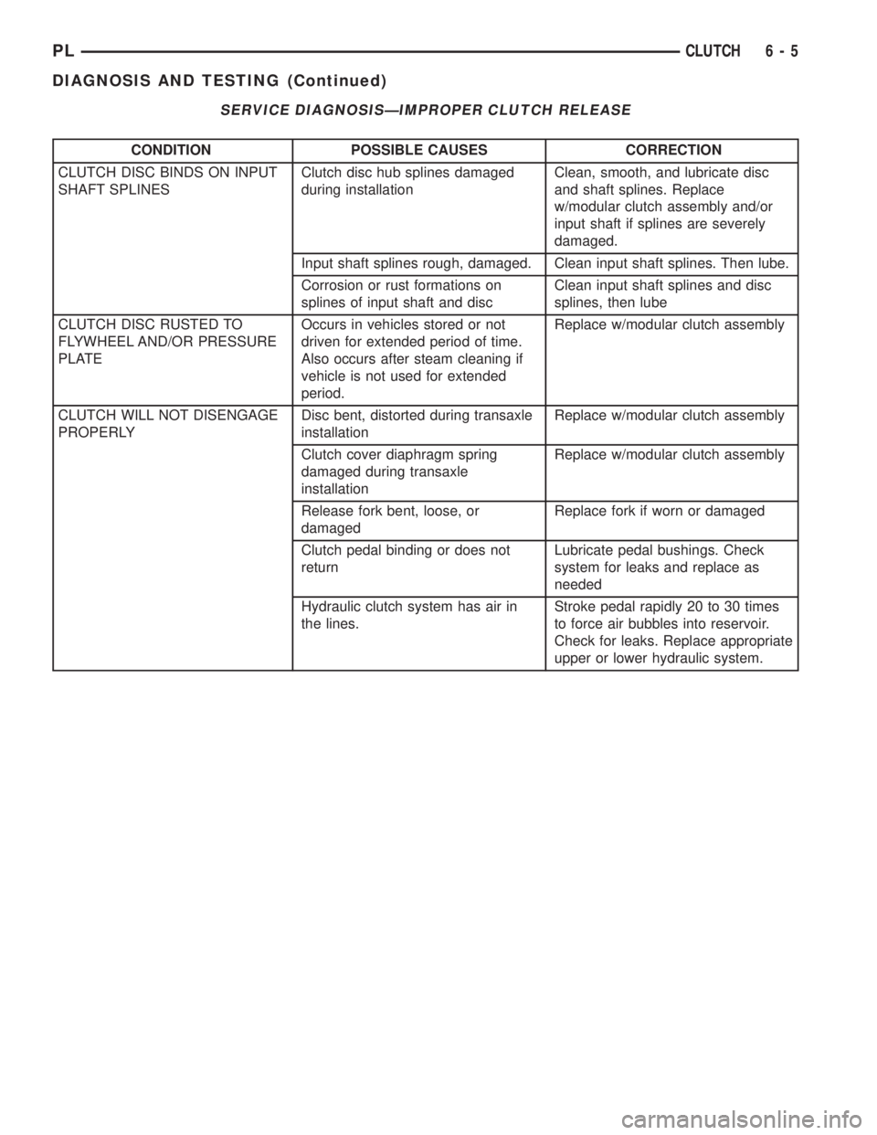
SERVICE DIAGNOSISÐIMPROPER CLUTCH RELEASE
CONDITION POSSIBLE CAUSES CORRECTION
CLUTCH DISC BINDS ON INPUT
SHAFT SPLINESClutch disc hub splines damaged
during installationClean, smooth, and lubricate disc
and shaft splines. Replace
w/modular clutch assembly and/or
input shaft if splines are severely
damaged.
Input shaft splines rough, damaged. Clean input shaft splines. Then lube.
Corrosion or rust formations on
splines of input shaft and discClean input shaft splines and disc
splines, then lube
CLUTCH DISC RUSTED TO
FLYWHEEL AND/OR PRESSURE
PLATEOccurs in vehicles stored or not
driven for extended period of time.
Also occurs after steam cleaning if
vehicle is not used for extended
period.Replace w/modular clutch assembly
CLUTCH WILL NOT DISENGAGE
PROPERLYDisc bent, distorted during transaxle
installationReplace w/modular clutch assembly
Clutch cover diaphragm spring
damaged during transaxle
installationReplace w/modular clutch assembly
Release fork bent, loose, or
damagedReplace fork if worn or damaged
Clutch pedal binding or does not
returnLubricate pedal bushings. Check
system for leaks and replace as
needed
Hydraulic clutch system has air in
the lines.Stroke pedal rapidly 20 to 30 times
to force air bubbles into reservoir.
Check for leaks. Replace appropriate
upper or lower hydraulic system.
PLCLUTCH 6 - 5
DIAGNOSIS AND TESTING (Continued)